Lexus LS 600hl Hybrid 2008 User manual

Hybrid
2008 Model
Revised (Includes 2010 Model Updates)
© 2009 Toyota Motor Corporation
All rights reserved. This document may not be
altered without the written permission of Toyota Motor Corporation.
10 LS 600h L ERG REV A (09/24/09)

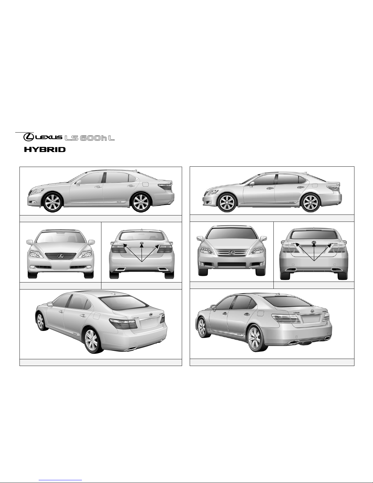
2008-2009 Model Year LS 600h L 2010 Model Year LS 600h L
F
-i-
oreword
This LS600h L gasoline-electric hybrid Emergency Response Guide
has been revised to include the changes of the 2010 model year LS600h
L. These changes include minor updates to the vehicle exterior and
interior. The important changes affecting the emergency responder are
the reshaped high voltage battery pack and the addition of pyrotechnic
front seat active headrests. The LS 600h L hybrid introduced in May
2007 continues to share the basic vehicle systems and features of the
conventional, non-hybrid, Lexus LS 460 L.
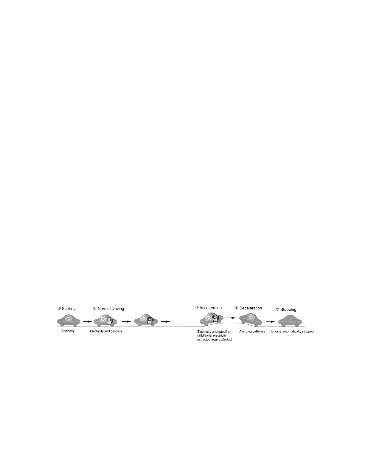
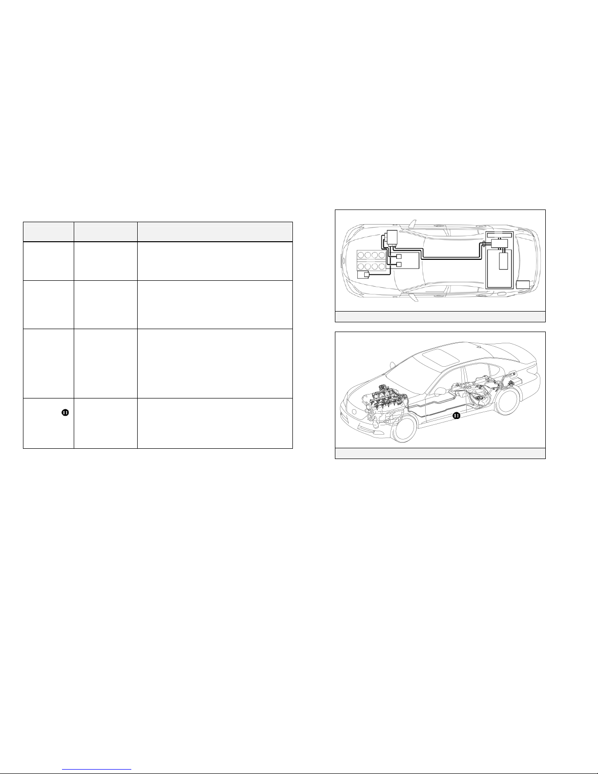
High voltage electricity powers the electric motor, generator, A/C
compressor, and power control unit (inverter/converter). Other
automotive electrical devices such as the horn, radio, and gauges are
powered from a separate 12 Volt auxiliary battery. Numerous
safeguards have been designed into the LS 600h L to help ensure the
high voltage, approximately 288 Volt, Nickel Metal Hydride (NiMH)
Hybrid Vehicle (HV) battery pack is kept safe and secure in an accident.
The LS 600h L utilizes the following electrical systems:
• Maximum 650 Volts AC
• Nominal 288 Volts DC
• Maximum 46 Volts AC / DC
• Nominal 12 Volts DC
LS 600h L Features:
• A mechanical all-wheel drive hybrid powertrain.
• A boost converter in the power control unit that boosts to 650 Volts
the available voltage to the electric motor.
• A high voltage Hybrid Vehicle (HV) battery pack rated at 288 Volts.
• A high voltage motor driven Air Conditioning (A/C) compressor
rated at 288 Volts.
• An Electric Power Steering (EPS) assist motor rated at 46 Volts.
• Active stabilizer suspension system motors rated at 46 Volts.
• A body electrical system rated at 12 Volts, negative chassis ground.
• Supplemental Restraint System (SRS) - dual stage frontal airbags,
front knee airbags, front seat and optional rear seat side airbags,
side curtain airbags, front and rear seat belt pretensioners, and when
equipped with an optional rear seat Ottoman, a passenger side rear
seat cushion airbag.
• Active headrests for the front seats (2010 model only)
High voltage electrical safety is an important factor in the emergency
handling of the LS 600h L Lexus Hybrid Drive. It is important to
recognize and understand the disabling procedures and warnings
throughout the guide.
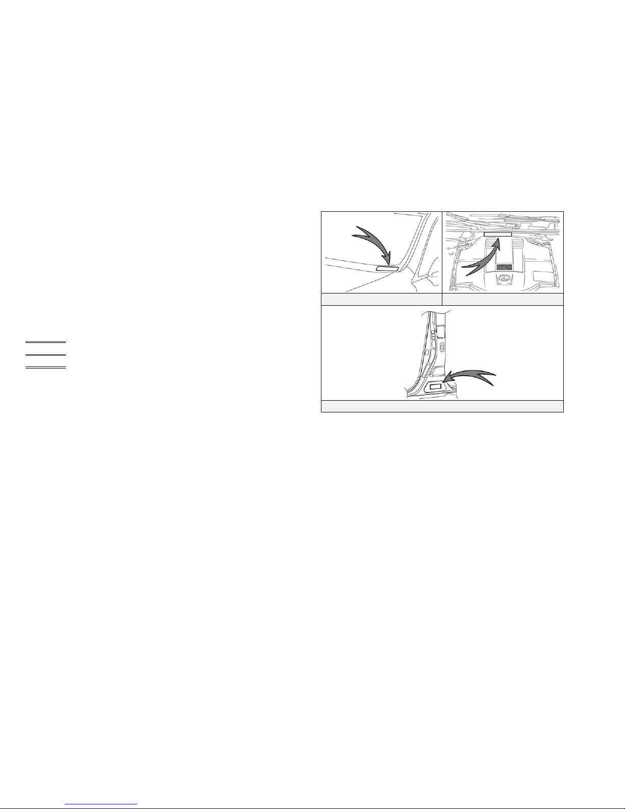
Additional topics in the guide include:
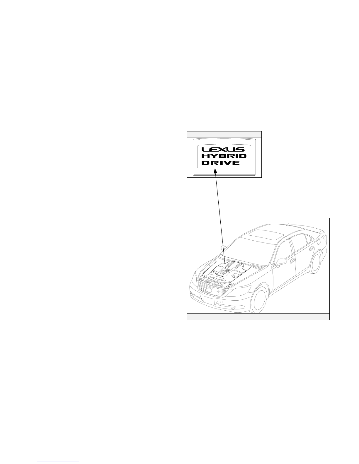
• Lexus LS 600h L identification.
• Major Lexus Hybrid Drive component locations and descriptions.
• Extrication, fire, recovery, and additional emergency response
information.
• Roadside assistance information.
This guide is intended to assist emergency responders in the safe
handling of a Lexus LS 600h L hybrid vehicle during an incident.
NOTE:
Emergency Response Guides for Lexus hybrid vehicles may be viewed at
http://techinfo.lexus.com.

-ii-
Table of Contents Page
About the LS 600h L 1
LS 600h L Identification 2
Lexus Hybrid Drive Component Locations & Descriptions 6
Smart Access System & Push Button Start 9
Lexus Hybrid Drive Operation 11
Hybrid Vehicle (HV) Battery Pack 12
46VoltSystem 13
Low Voltage Battery 14
High Voltage Safety 15
SRS Airbags & Seat Belt Pretensioners 16
Emergency Response 18
Extrication 18
Fire 25
Overhaul 26
Recovering/Recycling of NiMH HV Battery Pack 26
Spills 27
First Aid 27
Submersion 28
Roadside Assistance 29

About the LS 600h L
-1-
The LS 600h L sedan joins the RX 400h, RX450h, HS250h and GS
450h as a hybrid model for Lexus. Lexus Hybrid Drive means that the
vehicle contains a gasoline engine and an electric motor for power.
The two hybrid power sources are stored on board the vehicle:
1. Gasoline stored in the fuel tank for the gasoline engine.
2. Electricity stored in a high voltage Hybrid Vehicle (HV) battery pack
for the electric motor.
The result of combining these two power sources is improved fuel
economy and reduced emissions. The gasoline engine also powers an
electric generator to recharge the battery pack; unlike a pure all electric
vehicle, the LS 600h L never needs to be recharged from an external
electric power source.
Depending on the driving conditions one or both sources are used to
power the vehicle. The following illustration demonstrates how the LS
600h L operates in various driving modes.
During light acceleration at low speeds, the vehicle is powered by
the electric motor. The gasoline engine is shut off.
During normal driving, the vehicle is powered mainly by the
gasoline engine. The gasoline engine also powers the generator to
recharge the battery pack.
During full acceleration, such as climbing a hill, both the gasoline
engine and the electric motor power the vehicle.
During deceleration, such as when braking, the vehicle regenerates
kinetic energy from the wheels to produce electricity that recharges
the battery pack.
While the vehicle is stopped, the gasoline engine and electric motor
are off, however the vehicle remains on and operational.

LS 600h L dentificationI
In appearance, the 2010 model year LS 600h L is nearly identical to
the conventional, non-hybrid Lexus LS 460 L. The LS 600h L is a 4-
door sedan and the suffix “L” indicates a long wheelbase. Exterior,
interior, and engine compartment illustrations are provided to assist in
identification.
-2-
The alphanumeric 17 character Vehicle Identification Number (VIN)
is provided in the front windshield cowl, driver side door pillar, and
engine compartment.
Driver Side Windshield Engine Compartment Cowl
Base of Driver Side Door Pillar
Example VINs:
JTHDU46F840020208 (2008/2009 Models)
JTHDU1EF840020208 (4-seat models 2010 Model)
JTHDU5EF840020208 (5-seat models 2010 Model)
An LS 600h L is identified by the first 6 alphanumeric characters
JTHDU4, JTHDU1, or JTHDU5.

LS 600h L Identification (Continued)LS 600h L Identification (Continued)
ExteriorExterior
-3-
logos on the rear trunk.
logos on the rear door moldings.
Gasoline fuel filler door located on the driver side rear quarter panel.
2008/09 Models Exterior Driver Side View
2008/09 Models Exterior Front View 2008/09 Models Exterior Rear View
2008/09 Models Exterior Rear and Driver Side View
2010 Model Exterior Driver Side View
2010 Model Exterior Front View 2010 Model Exterior Rear View
2010 Model Exterior Rear and Driver Side View

LS 600h L Identification (Continued)LS 600h L Identification (Continued)
-4-
InteriorInterior
Interior View
Instrument Cluster View
The instrument cluster (speedometer, fuel gauge, warning lights) located
in the dash behind the steering wheel, is different than the one on the
conventional, non-hybrid LS 460 L.
The hybrid system indicator (power meter) is located next to the
tachometer on 2008/09 models and next to the speedometer on the 2010
model.
NOTE:
If the vehicle is shut off, the instrument cluster gauges will be “blacked
out”, not illuminated.
2010 Model
2008/09 Models

LS 600h L Identification (Continued)LS 600h L Identification (Continued)
Engine CompartmentEngine Compartment
5.0-liter aluminum alloy gasoline engine. Logo on Cover
Logo on the plastic engine cover.
-5-
Engine Compartment View

Lexus Hybrid Drive Component Locations &
Descriptions
Lexus Hybrid Drive Component Locations &
Descriptions
-6-
Component Location Description
12 Volt
Auxiliary
Battery
Trunk Driver Side A lead-acid battery that supplies power to
the low voltage devices.
Hybrid
Vehicle (HV)
Battery Pack
Trunk Area,
Mounted behind
Rear Seat
288 Volt Nickel Metal Hydride (NiMH)
battery pack consisting of 20 low voltage
(14.4 Volt) modules connected in series.
Power
Cables Undercarriage
and Engine
Compartment
Orange colored power cables carry high
voltage Direct Current (DC) between the
HV battery pack, power control unit, and
A/C compressor. These cables also carry 3-
phase Alternating Current (AC) between the
power control unit, electric motor, and
generator.
Inverter/
Converter Engine
Compartment Boosts and inverts the high voltage
electricity from the HV battery pack to 3-
phase AC electricity that drives the electric
motor. The power control unit also
converts AC electricity from the electric
generator and electric motor (regenerative
braking) to DC that recharges the HV
battery pack.
Gasoline
Engine Engine
Compartment Provides two functions:
1) Powers vehicle.
2) Powers generator to recharge the HV
battery pack.
The engine is started and stopped under
control of the vehicle computer.
Electric
Generator Transmission 3-phase high voltage AC generator that is
contained in the transmission and recharges
the HV battery pack.
Electric
Motor Transmission 3-phase high voltage AC permanent magnet
electric motor contained in the transmission
and drives the four wheels through the
transfer case and propeller shafts.
2008/09 Lexus Hybrid Drive Components
2008/09 Components (Top View) and High Voltage Power Cables
2010 Lexus Hybrid Drive Components

Lexus Hybrid Drive Component Locations &
Descriptions (Continued)
Lexus Hybrid Drive Component Locations &
Descriptions (Continued)
-7-
2010 Components (Top View) and High Voltage Power Cables
Fuel Tank and Fuel Lines
Component Location Description
A/C
Compressor
(with
Inverter)
Engine
Compartment 3-phase high voltage AC electrically driven
motor compressor.
DC-DC
Converter
for 12 Volt
Auxiliary
Battery
Inside HV Battery
Pack in Trunk Converts 288 Volts from the HV battery
pack to 12 Volts for low voltage vehicle
power.
DC-DC
Converter
for EPS and
Active
Stabilizer
Suspension
System
On HV Battery
Pack Converts 288 Volts from the HV battery
pack to 46 Volts for EPS and active
stabilizer suspension system power. Dull
yellow colored sheathing identifies 46 Volt
wires that are routed under the vehicle body
to power the EPS and the active stabilizer
suspension system.
Fuel Tank and
Fuel Lines Undercarriage,
Driver Side and
Center
The fuel tank provides gasoline via fuel
lines to the engine. The source fuel lines
are routed under the vehicle along the
center tunnel and the return line is routed
along the driver side under the floor pan.

-8-
Lexus Hybrid Drive Component Locations &
Descriptions (Continued)
Key Specifications:
Gasoline Engine: 390 hp (290 kW), 5.0-liter Aluminum Alloy Engine
Electric Motor: 221 hp (165 kW), Permanent Magnet Motor
Transmission: Automatic Only (electrically controlled
continuously variable transmission)
HV Battery: 288 Volt Sealed NiMH Battery
Curb Weight: 5,049 lbs / 2,290 kg (2008/09)
5,360 lbs / 2,420 kg (2010)
Fuel Tank: 22.1 gals / 84 liters
Fuel Economy
Ratings:
20/22 (City/Hwy) miles/gal
11.3/8.0 (City/Hwy) liters/100 km
Frame Material: Steel Unibody
Body Material: Steel Panels except for Aluminum Hood
Steel Unibody
Aluminum

S
-9-
mart Access System & Push Button Start
The LS 600h L smart access system consists of a smart key
transceiver that communicates bi-directionally enabling the vehicle to
recognize the smart key in close proximity to the vehicle. Once
recognized, the smart key will allow the user to lock and unlock the
doors without pushing smart key buttons, and start the vehicle without
inserting it into an ignition switch.
Smart key features:
• Passive (remote) function to lock/unlock the doors and start the
vehicle.
• Wireless transmitter buttons to lock/unlock the doors and unlock
the trunk.
• Hidden metal cut key to lock/unlock the doors and trunk from the
exterior.
The LS 600h L is equipped with two types of smart keys:
• Smart key (fob)
• Card smart key
The card smart key is designed to be stored in a wallet and has all the
same functions as the smart key (fob), except push buttons.
Door (Lock/Unlock)
Three methods are available to lock/unlock the doors.
1. Pushing wireless smart key lock/unlock buttons.
2. Touching the sensor on the backside of any exterior door handle, with
the smart key in close proximity to the vehicle, unlocks the doors.
Pushing the lock button on any exterior door handle locks the doors.
3. Removing the driver door handle cover, inserting the hidden metal cut
key in the driver door lock and turning the key clockwise once unlocks
the driver door, twice unlocks all doors. To lock all doors turn the key
counter-clockwise once. Only the driver door contains an exterior door
lock for the metal cut key.
Smart Key (Fob) Hidden Metal Cut Key for Door Lock
(Smart Key)
Card Smart Key and Hidden Metal Cut
Key for Door Lock Driver Door Unlock Touch Sensor and
Lock Button
Hidden Front Driver Door Lock
Release Button
Unlock Touch
Sensor
Release Button
Lock
Button
Cover
Use the Hidden Metal Cut Key
Remove the Cover

S
-10-
mart Access System & Push Button Start (Continued)
Vehicle Starting/Stopping
The smart key has replaced the conventional metal cut key, and the power
button with an integral status indicator light has replaced the ignition switch.
The smart key only needs to be in proximity to the vehicle to allow the
system to function.
• With the brake pedal released, the first push of the power button
operates the accessory mode, the second push operates the ignition-on
mode, and the third push turns the ignition off again.
Ignition Mode Sequence (brake pedal released):
• Starting the vehicle takes priority over all other ignition modes and is
accomplished by depressing the brake pedal and pushing the power
button once. To verify the vehicle has started, the power button status
indicator light is off and the READY light is illuminated in the
instrument cluster.
• If the internal smart key battery is dead, use the following method to
start the vehicle.
1. Touch the Lexus emblem side of the smart key to the power
button (a buzzer will sound).
2. Within 10 seconds after the buzzer sounds, push the power
button with the brake pedal depressed (the READY light will
illuminate).
• Once the vehicle has started and is on and operational (READY-ON),
the vehicle is shut off by bringing the vehicle to a complete stop, placing
the gearshift lever in Park, and then depressing the power button once.
Ignition Mode Power Button Indicator Light
Off Off
Accessory Amber
Ignition-On Amber
Brake Pedal Depressed Green
Vehicle Started (READY-ON) Off
Malfunction Blinking Amber
Power Button with Integral Status
Indicator Light Ignition Modes (Brake Pedal
Released)
Starting Sequence
(Brake Pedal Depressed) Smart Key Recognition
(When Smart Key Battery is Dead)
Accessor
y
Ignition-On
Vehicle Of
f
Button Push Button Push
Button Push

EV Mode Switch EV Mode and ECO Mode Switch
Instrument Cluster READY Indicator
2010 Model
2010 Model
2008/09 Models
2008/09 Models
-11-
Lexus Hybrid Drive Operation
Once the READY indicator is illuminated in the instrument cluster,
the vehicle may be driven. However, the gasoline engine does not
idle like a typical automobile and will start and stop automatically. It
is important to recognize and understand the READY indicator
provided in the instrument cluster. When lit, it informs the driver that
the vehicle is on and operational even though the gasoline engine may
be off and the engine compartment is silent.
Vehicle Operation
• With the LS 600h L, the gasoline engine may stop and start at any time
while the READY indicator is on.
• Never assume that the vehicle is shut off just because the engine is off.
Always look for the READY indicator status. The vehicle is shut off
when the READY indicator is off.
• The vehicle may be powered by:
1. The electric motor only.
2. The gasoline engine only.
3. A combination of both the electric motor and the gasoline
engine.
• The vehicle computer determines the mode in which the vehicle operates
in order to improve fuel economy and reduce emissions. Two features
on the LS600h L are EV (Electric Vehicle) mode and ECO (Economy)
mode:
1. EV Mode: When activated, and certain conditions have been
met, the vehicle operates with the electric motor powered by
the HV battery.
2. ECO Mode: When activated, this mode helps enhance fuel
economy on trips that involve frequent braking and
acceleration (2010 model only).

H
-12-
ybrid Vehicle (HV) Battery Pack
The LS 600h L features a high voltage Hybrid Vehicle (HV) battery pack
that contains sealed Nickel Metal Hydride (NiMH) battery modules.
HV Battery Pack
• The HV battery pack is enclosed in a metal case and is securely mounted in
the trunk area behind the rear seat. The metal case is isolated from high
voltage and concealed by fabric covers.
• The HV battery pack consists of 20 low voltage (14.4 Volt) NiMH battery
modules connected in series to produce approximately 288 Volts. Each
NiMH battery module is non-spillable and sealed in a metal case.
• The electrolyte used in the NiMH battery module is an alkaline mixture of
potassium and sodium hydroxide. The electrolyte is absorbed into the
battery cell plates and will not normally leak, even in a collision.
• The shape of the 2010 LS 600h L battery pack has been changed.
HV Battery Pack
Battery pack voltage 288 V
Number of NiMH battery modules in the pack 20
NiMH battery module voltage 14.4 V
NiMH battery module dimensions 1 x 21 x 3.3 in
(18 x 542 x 86 mm)
NiMH module weight 4.8lbs (2.2kg)
NiMH battery pack dimensions (2008/09 Models) 20 x 33x 10 in
(515 x 842 x 257 mm)
NiMH battery pack dimensions (2010 Model) 17 x 33x 17.3 in
(432 x 842 x 439 mm)
NiMH battery pack weight (2008/09 Models) 148 lbs
(67 kg)
NiMH battery pack weight (2010 Model) 174 lbs
(79 kg)
Components Powered by the HV Battery Pack
HV Battery Pack Recycling
• The HV battery pack is recyclable. Contact the nearest Lexus dealer or:
United States: (800) 255-3987, Canada: (800) 265-3987
2008/09 Models HV Battery Pack 2008/09 Models HV Battery Pack
(Viewed from the Trunk)
2010 Model HV Battery Pack 2010 Model HV Battery Pack
(Viewed from the Trunk)
•
Electric Motor
•
Power Cables
• Power Control Unit • Electric Generator
• A/C Compressor
• DC-DC Converter for 12 Volt Auxiliary Battery
• DC-DC Converter for EPS and Active Stabilizer Suspension System

4
-13-
6 Volt System
The LS 600h L is equipped with a 46 Volt electrical system that powers the
Electric Power Steering (EPS) assist motor in the engine compartment and the
optional Active Stabilizer Suspension System motors for the front and rear
stabilizer bars.
• 46 Volt electrical system wires are bundled in dull yellow sheathing for
identification.
• The 46 Volt electrical system does not contain a storage battery. It is
powered by converting high voltage battery power. The wires are routed
underneath the vehicle from the HV battery pack DC-DC converter.
• If the HV battery pack malfunctions, backup power is provided to the EPS
motor by boosting the 12 Volt electrical system.
46 Volt Electric Power Steering System
Optional 46 Volt Active Stabilizer Suspension System
Electric Power Steering
ECU
Assist Motor
NOTE:
46 Volts has a higher arc potential than 12 Volts.
Front Active Stabilizer Control
ECU
2010 DC/DC Converter
(
for Active Stabilizer and EPS
)
Front Active Stabilizer Motor
Rear Active Stabilizer
Moto
r
2008/09 DC/DC Converter
(
for Active Stabilizer and EPS
)
Rear Active Stabilizer Control
ECU

L
-14-
ow Voltage Battery
Auxiliary Battery
• The LS 600h L contains a sealed lead-acid 12 Volt battery. The 12 Volt
auxiliary battery powers the vehicle’s electrical system similar to a
conventional vehicle. As with conventional vehicles, the negative terminal
of the auxiliary battery is grounded to the metal chassis of the vehicle.
• The auxiliary battery is located in the trunk. It is concealed by a fabric
cover on the driver side in the rear quarter panel well.
12 Volt Auxiliary Battery Fabric Cover 12 Volt Auxiliary Battery Mounted in
Trunk (Driver Side)
NOTE:
An underhood label shows the location of the HV battery (traction battery)
and 12 Volt auxiliary battery.
Battery Location Label

H
-15-
igh Voltage Safety
The HV battery pack powers the high voltage electrical system with DC
electricity. Positive and negative orange colored high voltage power cables are
routed from the battery pack, under the vehicle floor pan, along the propeller
shaft and transmission tunnel to the power control unit. The power control unit
contains a circuit that boosts the HV battery voltage from 288 to 650 Volts DC.
The power control unit creates 3-phase AC to power the motor and generator
located in the transmission. Power cables are routed from the power control
unit to each high voltage motor (electrical motor, electric generator, and A/C
compressor). The following systems are intended to help keep occupants in the
vehicle and emergency responders safe from high voltage electricity:
High Voltage Safety System
• A high voltage fuse provides short circuit protection in the HV battery
pack.
• Positive and negative high voltage power cables connected to the HV
battery pack are controlled by 12 Volt normally open relays . When the
vehicle is shut off, the relays stop electrical flow from leaving the HV
battery pack.
• Both positive and negative power cables are insulated from the metal
body. High voltage electricity flows through these cables and not through
the metal vehicle body. The metal vehicle body is safe to touch because it
is insulated from the high voltage components.
• A ground fault monitor continuously monitors for high voltage leakage
to the metal chassis while the vehicle is running. If a malfunction is
detected, the hybrid vehicle computer will illuminate the master warning
light in the instrument cluster and indicate “CHECK HYBRID
SYSTEM” on the multi-information display.
High Voltage Safety System – Vehicle Shut Off (READY-OFF)
High Voltage Safety System – Vehicle On and Operational (READY-ON)
WARNING:
The high voltage system may remain powered for up to 10 minutes
after the vehicle is shut off or disabled. To prevent serious injury or
death from severe burns or electric shock, avoid touching, cutting, or
breaching any orange high voltage power cable or high voltage
com
p
onent.

S
-16-
RS Airbags & Seat Belt Pretensioners
Standard Equipment
• Electronic frontal impact sensors (2) are mounted in the engine
compartment as illustrated.
• Front seat belt pretensioners are mounted near the base of the B-pillars .
• Rear seat belt pretensioners are mounted near the C-pillar on the rear
seatbacks.
• A frontal dual stage driver airbag is mounted in the steering wheel hub.
• A frontal twin-chamber shaped dual stage passenger airbag is integrated
into the dashboard and deploys through the top of the dashboard.
• The SRS computer , which contains an impact sensor, is mounted on the
floor pan underneath the center armrest console.
• Front electronic side impact sensors (2) are mounted near the base of the B-
pillars .
• Rear electronic side impact sensors (2) are mounted near the base of the C-
pillars .
• Front seat side airbags are mounted in the seatbacks.
• Side curtain airbags are mounted along the outer edge inside the roof
rails.
• Front knee airbags are mounted on the driver side and passenger side
lower portion of the dash.
• Pyrotechnic front seat active headrests (2010 model only see description
on page 23).
Optional Equipment
• Rear seat side airbags mounted in the rear seats are optional equipment.
• The optional passenger side rear ottoman power seat contains an airbag
mounted in the bottom seat cushion.
• The optional pre- collision safety system contains a radar sensory system,
occupant seat sensor, and an electric motor-pyrotechnic pretensioner
system. During a pre-collision event, an electric motor in the pretensioners
retracts the slack in the front seatbelt. When conditions stabilize the electric
motor will reverse itself. When the airbags deploy, the pyrotechnic
pretensioners function normally.
Electronic Impact Sensors, Front Seat Active Headrests, Front and Optional Rear
Seat Side Airbags
Standard Frontal Airbags, Seat Belt Pretensioners, Knee Airbags, Side Curtain
Airbags, and Optional Seat Cushion Airbag
Side Curtain Airbag Inflator in Roof Rail
WARNING:
The SRS may remain powered for up to 90 seconds after the vehicle is shut of
f
or disabled. To prevent serious injury or death from unintentional SRS
deployment, avoid breaching the SRS components.

S
-17-
RS Airbags & Seat Belt Pretensioners (Continued)
NOTE:
The front seatback mounted side airbags and the side curtain airbags may
deploy independently of each other.
The knee airbags are designed to deploy simultaneously with the frontal
airbags and seat belt pretensioners.
The LS 600h L is equipped with a standard front passenger occupant
classification system that may prohibit the deployment of the front
passenger frontal airbag, knee airbag, seatback mounted side airbag, front
seat active headrest and seat belt pretensioners. If the passenger occupant
classification system prohibits deployment during an SRS event, the
passenger SRS will not re-arm nor deploy.
SRS System Diagram
Frontal, Knee, Front Seatback Mounted Side, Side Curtain, Optional Rear Seat
Side and Seat Cushion Airbags.
Driver Knee Airbag and Inflator
Passenger Side Rear Seat Cushion Airbag (Standard with Optional Ottoman Seat)
Optional
Ottoman with
Seat Cushion
Airbag
Side Airbag Senso
r
Front Seat Active
Headrest
Knee Airbag
Front Airbag
Sensors
Passenger Frontal Airbag Front Seat
Side Airba
g
Knee Airbag
Driver Frontal Airbag
Front Seat Active
Headrest
Front Seat
Side Airba
g
Front Seat Belt Pretensione
r
Seat Cushion Airbag
Rear Side Airbag Senso
r
Rear Seat
Side Airba
g
Front Seat Belt
Pretensioner
Rear Seat
Side Airba
g
Rear Side Airbag Senso
r
Front Seat Belt Pretensione
r
Side Airbag Senso
r
Table of contents
Other Lexus Automobile manuals

Lexus
Lexus IS250 2006 User manual

Lexus
Lexus 2004 GX470 User manual

Lexus
Lexus GS F User instructions

Lexus
Lexus LC 500h User manual

Lexus
Lexus Navigation System SC430 User manual

Lexus
Lexus GS 450h User manual

Lexus
Lexus 2014 RX 450h User manual

Lexus
Lexus GS450h 2008 User manual

Lexus
Lexus 2015 LX 570 User manual

Lexus
Lexus ES350 2012 User manual

Lexus
Lexus GS250 User manual

Lexus
Lexus RCF 2022 User manual

Lexus
Lexus RX 450h 2022 User manual

Lexus
Lexus GS 350 2014 User manual

Lexus
Lexus ES-300 2001 User manual

Lexus
Lexus GX550 2024 User manual

Lexus
Lexus 2015 ES 300h User manual

Lexus
Lexus 2015 ES 300h User manual

Lexus
Lexus GS 450h 2006 User manual

Lexus
Lexus RX450h User manual