LFX GROUP BARREL 250 User manual

USER’S MANUAL
SCANNER
www.lfxgroup.com
BARREL 250
KEEP THIS MANUAL FOR FUTURE NEEDS

For your own safety, please read this user manual carefully before installing the device.
Keepthisdeviceawayfromrainandmoisture!
Unplugmainsleadbeforeopeningthehousing.
Every person involved with the installation, operation and maintenance of this device has to:
-be qualified
-follow carefully the instructions of this manual
INTRODUCTION:
Thank you for having chosen this professional moving head.
You will see you have acquired a powerful and versatile device.
Unpack the device. Inside the box you should find: the fixture device, a power cable, an
XLR connection cable, a safety cable and this manual. Please check carefully that there is no damage
caused by transportation. Should there be any, consult your dealer and don’t install this device.
Features
·Pan movement: pan 156°
·Tilt movement: tilt 45°
·3 operation mode: DMX controlled, stand alone or sound activated via built in microphone
·9 colors plus white, with two direction rainbow effect,
Switchable colour change (mode 1: only full colours, mode 2: colour-change at every position)
·7rotating gobos plus open, with different speed gobo shaking effect
·strobe effect : 0~10 flashes per second or random strobe
·8 preset programs selectable
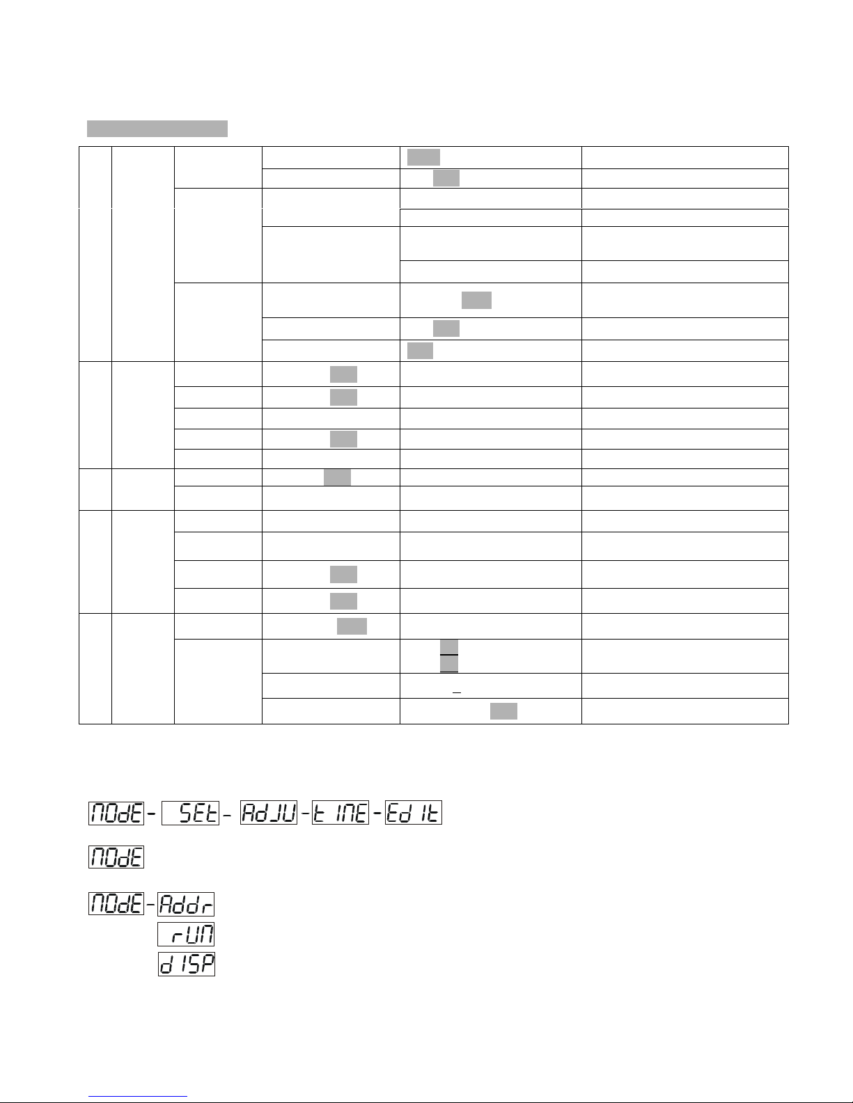
·Control board with 4-digit display and foil-keyboard for adjusting the DMX-starting address,
Pan/tilt-Reverse, Program, Reset, lamp on/off, operating hours and etc
·digital display can be turn 180° reverse to fit for different installation position
·local or remote resetting
·auto test for all functions
·value of each DMX-channel can be displayed
·save program : edit and save the program to the incorporated EEPROM through the front control
panel or external controller; can save maximum 48 scenes, and run the saved program by the “run”
menu from the front control panel
- 2 - WIT044 V1.6-03NR

SAFETY INSTRUCTIONS
CAUTION
Be very careful during installation. Since you will be working with a dangerous
voltage you can suffer a life-threatening electric shock when touching live wires.
This device has left the factory in perfect condition. In order to maintain this condition and to ensure
a safe operation, it is absolutely necessary for the user to follow the safety instructions and warning
notes written in this user manual.
IMPORTANT
Damages caused by the disregard of this user manual are not subject to warranty.
The dealer will not accept liability for any resulting defects or problems.
If the device has been exposed to temperature changes due to environmental changes, do not switch
it on immediately. The arising condensation could damage the device. Leave the device switched off
until it has reached room temperature.
This device falls under protection-class I. Therefore it is essential that the device be earthed.
The electric connection must carry out by qualified person.
Make sure that the available voltage is not higher than stated at the end of this manual.
Make sure the power cord is never crimped or damaged by sharp edges. If this would be the case,
replacement of the cable must be done by an authorized dealer.
Always disconnect from the mains, when the device is not in use or before cleaning it. Only handle
the power cord by the plug. Never pull out the plug by tugging the power cord.
During initial start-up some smoke or smell may arise. This is a normal process and does not
necessarily mean that the device is defective, it should decrease gradually.
- 3 - WIT044 V1.6-03NR

CAUTION
Never touch the device during operation!
The housing may heat up
CAUTION
Never look directly into the light source,
as sensitive persons may suffer an epileptic shock.
Please be aware that damages caused by manual modifications to the device are not subject to
warranty. Keep away from children and non-professionals.
GENERAL GUIDELINES
This device is a lighting effect for professional use on stages, in discotheques, theatres, etc.
This fixture is only allowed to be operated with the max alternating current which stated in the
technical specifications in the last page of this manual, the device was designed for indoor use only.
Lighting effects are not designed for permanent operation. Consistent operation breaks may ensure
that the device will serve you for a long time without defects. Do not shake the device.
Avoid brute force when installing or operating the device.
While choosing the installation-spot, please make sure that the device is not exposed to extreme heat,
moisture or dust. The minimum distance between light-output from the
projector and the illuminated surface must be more than 0,5 meter.
Always fix the fixture with an appropriate safety cable if you use the quick lock cam in hanging up
the fixture, please make sure the 4 quick lock fasteners turned in the quick lock holes correctly.
Operate the device only after having familiarized with its functions. Do not permit operation by
persons not qualified for operating the device. Most damages are the result of unprofessional
operation.
Please use the original packaging if the device is to be transported.
For safety reasons, please be aware that all modifications on the device are forbidden.
If this device will be operated in any way different to the one described in this manual, the product
may suffer damages and the guarantee becomes void. Furthermore, any other operation may lead to
short-circuit, burns, electric shock, lamp explosion, crash, etc.
- 4 - WIT044 V1.6-03NR

INSTALLATION INSTRUCTIONS
a) Installing or replacing the lamp
CAUTION
Only install the lamp with the device unplugged from the mains.
CAUTION
The lamp has to be replaced when it is damaged or deformed.
Before replacing the lamp let the lamp cool down, because during operation, the lamp can
reach very high temperature.
During the installation of halogen lamps do not touch the glass bulbs bare handed. Always use a
cloth to handle the lamps during insertion and removal.
Do not install lamps with a higher wattage. They generate higher temperatures than which the device
was designed for.
For the installation, you need one: □CDMT150 G12 lamp ;
□
√MSD250/2 GY9.5 lamp ;
Procedure :
1 2 3 4
1) Unscrew the 2 screws on the back of the housing, holding the plate where the lamp is underneath.
2) Gently pull the socket holder using the knob in the middle.
3) Carefully insert the lamp into the socket. Please remember there is only one way to insert the lamp.
Gently slide the lamp and its lamp holder back into place and fasten the 2 screws.
4) On the access plate there are 3 small screws marked 1,2 and 3.which are used to adjust the lamp
holder in the lamp housing. You can adjust the 3 screws to fine-turn the position of the lamp to get
the maximum light output as shown below.
- 5 - WIT044 V1.6-03NR

Please remember the lamp is not a hot-restrike type, you must wait for approximately 10
minutes after having turned off the lamp before you can turn it back on again.
CAUTION
Do not operate this device with open cover
b) Mounting the device
CAUTION
Please consider the EN 60598-2-17 and the other respective national norms during the
installation. The installation must only be carried out by a qualified person.
The installation of the effect has to be built and constructed in a way that it can hold 10 times the
weight for 1 hour without any harming deformation.
The installation must always be secured with a secondary safety attachment, e.g. an appropriate
safety cable.
Never stand directly below the device when mounting, removing or servicing the fixture.
The operator has to make sure the safety relating and machine technical installations are approved by
an expert before taking the device into operation for the first time.
These installations have to be approved by a skilled person once a year.
CAUTION
Before taking into operation for the first time,
the installation has to be approved by an expert.
- 6 - WIT044 V1.6-03NR

Cautions:
The effect should be installed outside areas where persons may reach it, walk by or be seated.
CAUTION
When installing the device, make sure there is no highly
inflammable material within a distance of min. 0,5m
Overhead mounting requires extensive experience, including amongst others calculating
working load limits, installation material being used, and periodic safety inspection of all
installation material and the device. If you lack these qualifications, do not attempt the
installation yourself. Improper installation can result in bodily injury.
CAUTION
The electric connection must only be carried out by a qualified electrician.
Before mounting make sure that the installation area can hold a minimum point load of 10 times the
device’s weight.
Connect the fixture to the mains with the power plug.
installation via the Omega holders
Screw one clamp each via a M10 screw and nut directly into the bracket of the scanner. Pull the safety-chain
through the bracket of the base and over the trussing system or a safe fixation spot.
- 7 - WIT044 V1.6-03NR

DMX-512 control connection
Connect the provided XLR cable to the female 3-pin XLR output of your controller and the other
side to the male 3-pin XLR input of the moving head. You can chain multiple
Moving head together through serial linking. The cable needed should be two core, screened cable
with XLR input and output connectors. Please refer to the diagram below.
DMX-512 connection with DMX terminator
For installations where the DMX cable has to run a long distance or is in an electrically noisy
environment, such as in a discotheque, it is recommended to use a DMX terminator. This helps in
preventing corruption of the digital control signal by electrical noise. The DMX terminator is simply
an XLR plug with a 120 Ωresistor connected between pins 2 and 3,which is then plugged into the
output XLR socket of the last fixture in the chain. Please see illustrations below.
Address1 Address9 Address17
Projector DMX start address selection
All fixtures should be given a DMX starting address when using a DMX signal, so that the correct
fixture responds to the correct control signals. This digital starting address is the channel number
from which the fixture starts to “listen” to the digital control information sent out from the DMX
controller. The allocation of this starting address is achieved by setting the correct number on the
display located on the base of the device.
You can set the same starting address for all fixtures or a group of fixtures , or make different
address for each fixture individually.
If you set the same address, all the units will start to “listen” to the same control signal from the same
channel number. In other words, changing the settings of one channel will affect all the fixtures
- 8 - WIT044 V1.6-03NR

simultaneously.
If you set a different address, each unit will start to “listen” to the channel number you have set,
based on the quantity of control channels of the unit. That means changing the settings of one
channel will affect only the selected fixture.
In the case of the spot head, which is a 11 channel fixture, you should set the starting address of the
first unit to 1, the second unit to 9 (8 + 1), the third to 17 (9 + 8), and so on.
Note:
The odes wn via them of DMX 512 data and lamp are sho display:
... .
Lamp on Lamp on
DMX OK DMX OK
NO DMX NO DMX
Lamp off Lampoff
1. After switching on, the device will automatically detect whether DMX 512 data is received or not. If the data is
received, the the display will show "A.001" with the actually set address. If there is no data received at the
DMX-input, the display will flash "A001" with the actually set address.
This situation can occur if:
- the 3 PIN XLR plug (cable with DMX signal from controller) is not connected with the input of the device.
- the controller is switched off or defective, if the cable or connector is defective or the signal wires are swap in the
input connector.
It’s necessary to insert the XLR termination plug (with 120 Ohm) in the last lighting in the link in order to ensure
proper transmission on the DMX data link.
2. If the lamp is on, the the display will show "A00.1" with the actually set address. If the lamp is off, the the
display will show "A001" with the actually set address.
Control Board
The Control Board offers several features: you can simply set the starting address, switch on and off the lamp, run
the pre-programmed program or make a reset.
The main menu is accessed by pressing the Mode/esc-button until the display starts flashing. Browse through the
menu by pressing the Up-button or Down-button. Press the Enter-button in order to select the desired menu. You
can change the selection by pressing the Up-button or Down-button. Confirm every selection by pressing the
Enter-button. You can leave every mode by pressing the Mode/esc-button . The functions provided are described in
the following sections.
- 9 - WIT044 V1.6-03NR

Default settings shaded.
VA L U A001~A511 (AXXX) DMX address setting
ADDR SLAV ON/OFF (SLAV) Slave setting
ALON (AU-A) Automatic Run in Stand Alone
AUTO MAST
(
AU-M
)
Automatic Run as Maste
r
ALON (SO-A) Sound-controlled Run in Stand
Alone
RUN
SOUN
MAST (SO-M) Sound-controlled Run as Master
VA L U D–XX D-00 (DXXX) Display the DMX 512 value of
each channel
RDIS ON/OFF Reverse display
0 MODE
DISP
CLDI ON/OFF Shut off LED display
RPAN ON/OFF Pan Reverse
RTIL ON/OFF Tilt Reverse
REST Reset
LODA ON/OFF Restore factory settings
1 SET
VER V-1.0~V-9.9 Software version
LADJ ON/OFF Lamp adjustment
2 ADJU TEST T–01~T–30 Test function of each channel
MATI 0000~9999(hours) Fixture running time
LATI 0000~9999(hours) Lamp running time
CLMT ON/OFF Clear fixture time
3 TIME
CLLT ON/OFF Clear lamp time
STEP S–01 ~S–48 Steps of Program Run
C–01~C–30 0 1 XX(00~FFH)
3 0 XX(00~FFH) Edit the channels of each scene
TIME T – – X(1~9) Time for each scene
4 EDIT SC01
~ SC48
CNIN ON/OFF Edit program via controller
Main functions
- Main menu 0
1. Press [MODE/ESC] to enter the main menu "MODE" (display flashing)
- 10 - WIT044 V1.6-03NR

2. Press [ENTER] and select "ADDR", “RUN” or "DISP" by pressing [UP] or [DOWN] button.
3. Press [ENTER] for selecting the desired sub menu.
- DMX address setting, Slave setting
- DMX address setting
With this function, you can adjust the desired DMX-address via the Control Board.
1. Select “VALU“ by pressing [UP] or [DOWN] button.
2. Press [ENTER], adjust the DMX address by pressing [UP] or [DOWN] button.
3. Press [ENTER] to confirm or pressing [MODE/ESC] to return to main menu.
- Slave setting
With this function, you can define the device as slave.
1. Select “SLAV” by pressing [UP] or [DOWN] button.
2. Press [ENTER], the display shows “ON” or “OFF”.
3. Press [UP] to select “ON” if you wish to enable this function or press [DOWN] to select “OFF” if you don’t.
4. Press [ENTER] to confirm or press [MODE/ESC] to return to main menu.
- Program Run, Master setting
With the function "RUN", you can run the internal program. You can set the number of steps under Step. You can
edit the individual scenes under Edit. You can run the individual scenes either automatically (AUTO), i.e. with the
adjusted Step-Time or sound-controlled (SOUN). The selection "ALON" means Stand Alone-mode and "MAST"
that the device is defined as master.
1. Select "AUTO" or "SOUN" by pressing [UP] or [DOWN] button.
2. Press [ENTER] for selecting the desired extension menu.
3. Select "ALON" or "MAST" by pressing [UP] or [DOWN] button.
4. Press [ENTER] to confirm or Press [MODE/ESC] to return to the main menu.
- Display the DMX-value, Reverse display, Shut off LED display
- 11 - WIT044 V1.6-03NR

- Display the DMX 512 value of each channel
With this function you can display the DMX 512 value of each channel.
1. Select "VALU" by pressing [UP] or [DOWN] button.
2. Press [ENTER] to confirm; the display shows“D-00”. In this setting, the DMX-adjustment of every
channel will be displayed.
3. Press [UP] or [DOWN] button in order to select the desired channel. If you select “D-14” the display
will only show the DMX-value of the 14th channel.
4. Press [ENTER] to confirm or Press [MODE/ESC] to return to the main menu.
5. The display shows "D- XX“, ”X” stands for the DMX-value of the selected channel.
- Reverse display
With this function you can rotate the display by 180°.
1. Select "RDIS" by pressing [UP] or [DOWN] button.
2. Press [ENTER], the display shows “ON” or “OFF”.
3. Press [UP] to select “ON” if you wish to enable this function or press [DOWN] button to “OFF” if you
don’t; the display will rotate by 180°.
4. Press [ENTER] to confirm or Press [MODE/ESC] to return to the main menu.
- Shut off LED display
With this function you can shut off the LED display after 2 minutes.
1. Select "CLDI" by pressing [UP] or [DOWN] button.
2. Press [ENTER], the display shows “ON” or “OFF”.
3. Press [UP] to select “ON” if you wish to enable this function or press [DOWN] button to “OFF” if you don’t.
4. Press [ENTER] to confirm or Press [MODE/ESC] to return to the main menu.
- Main menu 2
1. Press [MODE/ESC] to enter the main menu (display flashing).
2. Press [UP] or [DOWN] button. to select “SET”.
- Pan Reverse
With this function you can reverse the Pan-movement.
1. Select “RPAN” by pressing [UP] or [DOWN] button.
2. Press [ENTER], the display shows “ON” or “OFF”.
3. Press [UP] to select “ON” if you wish to enable this function or press [DOWN] button to “OFF” if you don’t.
4. Press [ENTER] to confirm or Press [MODE/ESC] to return to the main menu.
- Tilt Reverse
With this function you can reverse the Tilt-movement.
1. Select “RTIL” by pressing [UP] or [DOWN] button.
2. Press [ENTER], the display shows “ON” or “OFF”.
3. Press [UP] to select “ON” if you wish to enable this function or press [DOWN] button to “OFF” if you don’t.
- 12 - WIT044 V1.6-03NR

4. Press [ENTER] to confirm or Press [MODE/ESC] to return to the main menu.
- Reset
With this function you can Reset the device via the Control Board.
1. Select “REST” by pressing [UP] or [DOWN] button.
2. Press [ENTER], the display shows “ON” or “OFF”.
3. Press [UP] to select “ON” if you wish to enable this function or “OFF” if you don’t.
4. Press [ENTER] to confirm or Press [MODE/ESC] to return to the main menu.
- Restore factory settings
With this function you can restore the factory settings of the device. All settings will be set back to the default
values (shaded). Any edited scenes will be lost.
1. Select “LODA” by pressing [UP] or [DOWN] button.
2. Press [ENTER], the display shows “ON” or “OFF”.
3. Press [UP] to select “ON” if you wish to enable this function or press [DOWN] button to “OFF” if you don’t.
4. Press [ENTER] to confirm or Press [MODE/ESC] to return to the main menu.
- Software version
With this function you can display the software version of the device.
1. Select “VER” by pressing [UP] or [DOWN] button.
2. Press [ENTER], the display shows “V-X.X”, “X.X“ stands for the version number, e.g. “V-1.0”, “V-2.6”.
3. Press [MODE/ESC] to return to the main menu.
- Main menu 3
1. Press [MODE/ESC] to enter the main menu (display flashing).
2. Press [UP] or [DOWN] button to select “ADJU”.
- Lamp adjustment
With this function you can adjust the lamp via the Control Board. The shutter opens and the lamp can be adjusted.
In this mode, the device will not react to any control signal.
1. Select “LADJ” by pressing [UP] or [DOWN] button.
2. Press [ENTER], the display shows “ON” or “OFF”.
3. Press [UP] to select “ON” if you wish to enable this function or press [DOWN] button to “OFF” if you don’t.
4. Press [ENTER] to confirm or Press [MODE/ESC] to return to the main menu.
- Test function of each channel
With this function you can test each channel on its (correct) function. There are 8 DMX channels, and all except
channels 3, 7 and 8 can be tested.
1. Select “TEST” by pressing [UP] button.
2. Press [ENTER], the display shows “T-XX”, “X” stands for the channel number.
3. The current channel will be tested.
4. Select the desired channel by pressing [UP] or [DOWN] button.
5. Press [ENTER] to confirm or Press [MODE/ESC] to return to the main menu.
- 13 - WIT044 V1.6-03NR

- Main menu 4
1. Press [MODE/ESC] to enter the main menu (display flashing).
2. Press [UP] or [DOWN] button to select “TIME”.
- Fixture running time
With this function you can display the running time of the device.
1. Select “MATI” by pressing [UP] or [DOWN] button.
2. Press [ENTER], the display shows “XXXX”, “X“ stands for the number of hours.
3. Press [ENTER] to confirm or Press [MODE/ESC] to return to the main menu.
- Lamp running time
With this function you can display the running time of the lamp.
1. Select “LATI” by pressing [UP] button.
2. Press [ENTER], the display shows “XXXX”, “X“ stands for the number of hours.
3. Press [MODE/ESC] to return to the main menu.
- Clear fixture time
With this function you can clear the running time of the device.
1. Select “CLMT” by pressing [UP] or [DOWN] button.
2. Press [ENTER], the display shows “ON” or “OFF”.
3. Press [UP] to select “ON” if you wish to enable this function or press [DOWN] button to “OFF” if you don’t.
4. Press [ENTER] to confirm or Press [MODE/ESC] to return to the main menu.
- Clear lamp time
With this function you can clear the running time of the lamp. Please clear the lamp time every time you replace the
lamp.
1. Select “CLLT” by pressing [UP] or [DOWN] button.
2. Press [ENTER], the display shows “ON” or “OFF”.
3. Press [UP] to select “ON” if you wish to enable this function or press [DOWN] button to “OFF” if you don’t.
4. Press [ENTER] to confirm or Press [MODE/ESC] to return to the main menu.
- Main menu 5
1. Press [MODE/ESC] to enter the main menu (display flashing).
2. Press [UP] or [DOWN] button to select “EDIT”.
- Define the number of steps in Run
With this function you can define the number of steps in the Program Run.
1. Select “STEP” by pressing [UP] or [DOWN] button.
2. Press [ENTER], the display shows “S-XX”, “X” stands for the total amount of steps you want to save, so you
can call up to 48 scenes in “RUN”. For example if the “XX” is 05, it means that “RUN” will run the first 5 scenes
- 14 - WIT044 V1.6-03NR

you saved in “EDIT”.
3. Press [ENTER] to confirm or Press [MODE/ESC] to return to the main menu.
- Editing the channels of the individual scenes
With this function you can edit the program to be called up in
Run.
a) Editing via the Control Board
1. Select “SC01” by pressing [UP] or [DOWN] button.
2. Press [ENTER], the display shows “SCXX”, “X” stands
for the scene no. to be edited.
3. Change the scene no. by pressing [UP] or [DOWN] button.
4. Press [ENTER], the display shows “C-X”, “X” stands for
the channel no. Such as “C-01”, it means you are
editing channel 1 of the selected scene.
5. Select the channel no. you would like to edit by pressing
[UP] or [DOWN] button.
6. Press [ENTER] to enter editing for the selected
channel ,the fixture reacts to your settings. The display shows
the DMX value of the edited channel. Such as “ 11XX”, it
stands for in the channel 11 of the editing scene, the DMX value
is XX , XX is a hexadecimal number value “01-FF”.Adjust the
desired DMX value by pressing [UP] or [DOWN] button.
7. Press [ENTER] in order to edit other channels of this scene.
8. Repeat steps 5-9 until you finish setting all the DMX values
ompleted, the display will flash
[ENTER] to edit the time needed, the display shows
ssing [UP] or [DOWN] button.
iting, the display will change to the next scene
3-14 to edit and other scenes, you can edit and save a maximum of 48 scenes.
enes can be called
) Editing via the external controller
er now.
button.
]button.
ows "ON".
lly downloaded the first scene.
nloaded.
efined under “STEP” and the scenes can be called
for all channels of this scene.
9. Once all the channels c
“TIME”
10. Press
“t--X”,“X” stands for the time needed to run the current scene,
value “1-9”. For example, “t--2” means you need 2 seconds to run the current scene.
11. Adjust the desired time by pre
12. Press [ENTER] to save the settings for the scene you are ed
automatically.
13. Repeat step
14. Press [MODE/ESC] to exit. The number of steps can be defined under “STEP” and the sc
up under “RUN”
b
Call up the first scene in your controll
1. Select “SC01” by pressing [UP] or [DOWN]
2. Press [ENTER], the display shows “SC01”.
3. Press [ENTER], the display shows “C-01”.
4. Select "CNIN" by pressing [UP] or [DOWN
5. Press [ENTER], the display shows "OFF".
6. Press [UP] or [DOWN] button .the display sh
7. Press [ENTER], the display shows "SC02". You successfu
8. Adjust the Step-time as described above under point 12.
9. Call up the second scene in your controller now.
10. Repeat steps 5-11 until all desired scenes are dow
11. Press [MODE/ESC] to exit. The number of steps can be d
up under “RUN”
- 15 - WIT044 V1.6-03NR

DMX channel´s functions and their values :
hanne - Color Wheel 1 :
C l 1
0-12 Open / white
13-25 COL 1
26-38 COL 2
39-51 COL 3
52-64 COL 4
65-77 COL 5
78-90 COL 6
91-103 COL 7
104-116COL 8
117-127COL 9
128-187Forward
188-193No rotation
194-255Backwards r
0-13 Open
14-27 Rot. go
28-41 Rot. gobo 2 (metal)
42-55 Rot. gobo 3 (metal)
56-69 Rot. gobo 4 (metal)
70-83 Rot. gobo 5 (metal)
84-97 Rot. gobo 6 (metal)
98-115 Rot. gobo 7 (metal)
116-135Rot. gobo 1 (metal) s
136-155Rot. gobo 2 (metal) shake
156-175Rot. gobo 3 (metal) shake
176-195Rot. gobo 4 (metal) shake
196-215Rot. gobo 5 (metal) shake
216-235Rot. gobo 6 (metal) shake
236-255Rot. gobo 7 (metal) shake
C l 3
0-7 No rotation
forwards gob
28-135No rotation
136-255Backwards g
s rainbow effect from fast to slow
ainbow effect from slow to fast
Channel 2 - Rotating gobos, cont. rotation :
bo 1 (metal)
hake
hanne - rotating gobo rotation :
8-127 o rotation from fast to slow
1
obo rotation from slow to fast
- 16 - WIT044 V1.6-03NR

C0-31 Shutter closed
32-63 Dimmer (close t
64-95 Strobe effect slow to fast
96-127 No function (shutter open)
128-159Pulse-effect in sequences
160-191No function (shutter open)
192-223Random strobe effect slow
224-255No function (shutter open)
C l 6
(WhentheChannel6 is Bar
0-7 No rotation
forwards Bar
28-135No rotation
136-255backwards b
Ch l 7
0max speed
max to min s
26-235blackout by movem
236-245blackout by all wheel ch
246-255no function
Ch l 8
0-19 colour change normal
20-39 colour change to any po
40-59 No function
60-79 No function
80-99 Motor reset
00-119Internal prog
120-139Internal program 2
140-159Internal program 3
160-179Internal program 4
180-199Internal program 5
200-219Internal program 6
220-239Internal program 7
240-255Internal program 8
hannel 4 - Shutter, strobe:
o open)
to fast
Channel 5 - PAN movement 8bit :
hanne - TILT movement 8bit : rel or Dish)
8-127 rel or Dish rotation from fast to slow
1arrel or dish rotation from slow to fast
anne - Speed pan/tilt movement:
5-225 peed
2ent anging
anne – reset, internal programs:
sition
1ram 1
- 17 - WIT044 V1.6-03NR

Channe – reset, internal programs:(only use in ELC LAMP)l 8
0-127 colour change normal &Dimmer 0%~100%
28-140colour change to any position
141-153Motor reset
154-166Internal prog
167-179Internal program 2
180-192Internal program 3
193-205Internal program 4
206-218Internal program 5
219-231Internal program 6
232-244Internal program 7
245-255Internal program 8
1
ram 1
- 18 - WIT044 V1.6-03NR

CLEANING AND MAINTENANCE
g the inspection:
o be tightly connected and must
2) any deformations on the housing, color lenses, fixations and installation spots
1) st not show any traces of wearing and must not rotate with
2) power supply cables must not show any damage, material fatigue or sediments.
The following points have to be considered durin
1) All screws for installing the devices or parts of the device have t
not be corroded.
There must not be
(ceiling, suspension, trussing).
Mechanically moved parts mu
unbalances.
The electric
Further instructions depending on the installation spot and usage have to be adhered by a skilled
installer and any safety problems have to be removed.
CAUTION
Disconnect from mains before starting maintenance operation.
e recommend a frequent cleaning of the device. Please use a moist, lint- free cloth. Never use
ble parts inside the device except for the lamp. Please refer to the
genuine parts from your local dealer.
ECHNICAL SPECIFICATIONS
120VAC,50Hz;□208VAC,50Hz;□220VAC,50Hz; □
√230VAC,50Hz;□240VAC,50Hz;
e;
12KGS;
:errors and omissions for every information given in this manual excepted. All information
W
alcohol or solvents.
There are no servicea
instructions under “Installation instructions”.
Should you need any spare parts, please order
T
Power supply :
□98VAC,50Hz;□
□98VAC,50Hz;□120VAC,60Hz;□208VAC,60Hz;□220VAC,60Hz;□230VAC,60Hz;□240VAC,60Hz;
Power consumption : max. □230W , □
√400W
Lamp : □CDMT150 G12 socket, Metal Halid
□
√MSD250 GY9.5 socket, Metal Halide;
Motors : 6micromotors
Packing dimensions : 67x37x34cm
Net weight : □10.5KGS; □
√
Gross weight: □12.5KGS; □
√14KGS;
Remark
is subject to change without prior notice.
- 19 - WIT044 V1.6-03NR

Circuit Schematic
LAMP
BALLAST
IGNITER
THERMOSTAT
FUSE
CAP
TRANSFORMER
POWER
AC10VAC20V
FAN
GOBOMOTOR
GOBORO.MOTOR
COLORMOTOR
TILTMOTOR
PANMOTOR
STROBEMOTOR
BLPN
SCAN7CH-B01B
SCAN7CH-05
MINI-CONTROL-04B
Color ma
g
netic sensor
Light sensor
- 20 - WIT044 V1.6-03NR
Table of contents
Popular Dj Equipment manuals by other brands

Chauvet Professional
Chauvet Professional Rogue Outcast 1L Beam user manual

STARVILLE
STARVILLE MANIAC XH-1 owner's manual

Equinox Systems
Equinox Systems PRO DJ Booth Quad-colour Starcloth user manual

Iluminarc
Iluminarc LOGIC Wall Panel 16-Port Quick reference guide

Qtx
Qtx PAR-T Bar user manual

Beamz
Beamz BS150 user manual