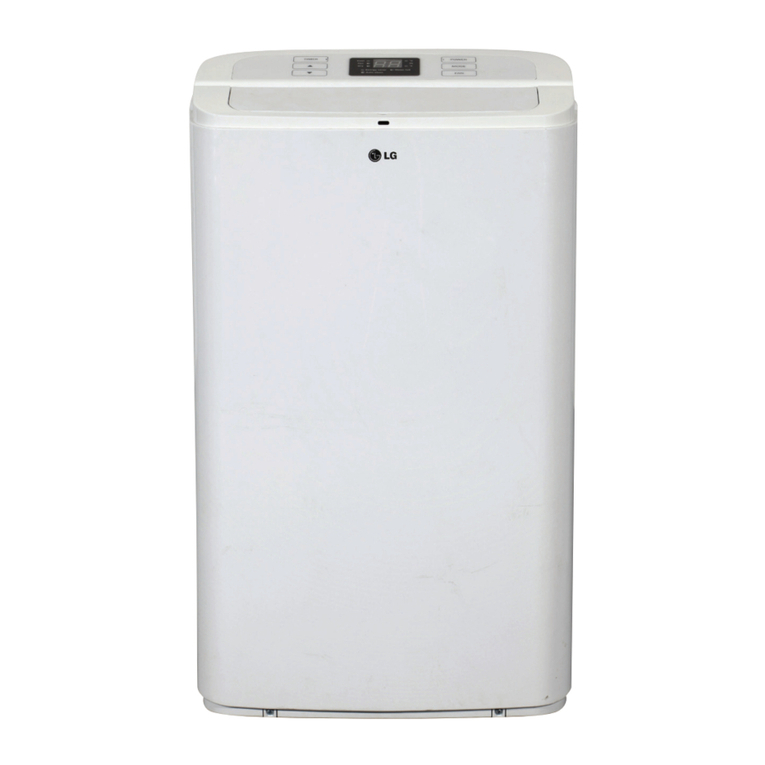
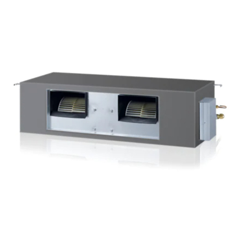
LG ARUN363DDA4 User manual

INSTALLATION MANUAL
AIR
CONDITIONER
Please read this installation manual completely before installing the product.
Installation work must be performed in accordance with the national wiring standards
by authorized personnel only.
Please retain this installation manual for future reference after reading it thoroughly.
www.lghvac.com
www.lg.com
Copyright © 2021 LG Electronics Inc. All Rights Reserved.
ENGLISH
SPLIT ROOFTOP UNIT(RTU)
MFL71810404
Rev.00

Due to our policy of continuous product innovation, some specifications may change without notification.
©LG Electronics U.S.A., Inc., Englewood Cliffs, NJ. All rights reserved. “LG” is a registered trademark of LG Corp.
2
PROPRIETARY DATA NOTICE
This document, as well as all reports, illustrations, data, information, and
other materials are the property of LG Electronics U.S.A., Inc., and are
disclosed by LG Electronics U.S.A., Inc., only in confidence.
Do not throw away, destroy, or lose this manual.
Please read carefully and store in a safe place for future reference.
Content familiarity required for proper installation.
The instructions included in this manual must be followed to prevent prod- uct
malfunction, property damage, injury, or death to the user or other people.
Incorrect operation due to ignoring any instructions will cause harm or damage.
A summary of safety precautions begins on page 4.
For more technical materials such as submittals, engineering
databooks, and catalogs, visit www.lghvac.com.
For continual product development, LG Electronics U.S.A., Inc. reserves the right to change specifications without notice.
©LG Electronics U.S.A., Inc.
This document, as well as all reports, illustrations, data, information, and other materials are the property of LG Electronics U.S.A., Inc.

Due to our policy of continuous product innovation, some specifications may change without notification.
©LG Electronics U.S.A., Inc., Englewood Cliffs, NJ. All rights reserved. “LG” is a registered trademark of LG Corp.
3
TABLE OF CONTENTS
SAFTY PRECAUTION ...................................................................................................................................................... 4
PRODUCT OVERVIEW.................................................................................................................................................... 8
CONTROLLEROVERVIEW............................................................................................................................................. 9
UNIT NOMENCLATURE................................................................................................................................................. 10
R410AREFRIGERANT..................................................................................................................................................11
PIPING CONNECTION...................................................................................................................................................12
ELECTRICALDATA....................................................................................................................................................... 13
DIMENSION.................................................................................................................................................................... 14
SERVICE AREA.............................................................................................................................................................. 16
REFRIGERANT FLOW DIAGRAM.................................................................................................................................. 17
WIRING DAIGRAM.......................................................................................................................................................... 19
INSTALLATION............................................................................................................................................................... 20
UNITPIPING...................................................................................................................................................................23
ELECTRICALINFORMATION........................................................................................................................................28
CHARGINGREFRIGERANT.......................................................................................................................................... 39

Due to our policy of continuous product innovation, some specifications may change without notification.
©LG Electronics U.S.A., Inc., Englewood Cliffs, NJ. All rights reserved. “LG” is a registered trademark of LG Corp.
4
SAFTY PRECAUTION
The instructions below must be followed to prevent product malfunction, property damage, injury or death to the user or
other people. Incorrect operation due to ignoring any instructions will cause harm or damage. The level of seriousness
is classified by the symbols below
INSTALLATION
TABELE OF SYMBOLS
DANGER
This symbol indicates an imminently hazardous situation which, if not avoided, will result in death or serious injury.
WARNING
This symbol indicates a potentially hazardous situation which, if not avoided, could result in death or serious injury.
CAUTION
This symbol indicates a potentially hazardous situation which, if not avoided, may result in minor or moderate injury.
Note:
This symbol indicates situations that may result in equipment or property damage accidents only.
This symbol indicates an action that should not be performed.
DANGER
Do not store or use flammable gas or combustibles
near the unit.
There is risk of fire, explosion, physical injury or death
Do not supply power to the unit until all wiring and
piping are completed or reconnected and checked.
There is risk of physical injury or death due to electric shock.
WARNING
Do not install or remove the unit by yourself (end-user).
Ask the dealer or an LG trained technician to install the
unit
Improper installation by the user may result in water leakage,
fire, explosion, electric shock, physical injury or death.
Always check for system refrigerant leaks after the unit
has been installed or serviced.
Exposure to high concentration levels of refrigerant gas may
lead to illness or death
Do not install the unit using defective hanging,
attaching, or mounting hardware.
There is risk of physical injury or death.
Wear protective gloves when handling equipment.
Sharp edges may cause personal injury.
Dispose of the packing materials safely.
•Packing materials, such as nails and other metal or
wooden parts may cause puncture wounds or other
injuries.
•Tear apart and throw away plastic packaging bags so that
children may not play with them and risk suffocation and
death.
Do not install the unit in any location exposed to open
flame or extreme heat.
hands.
There is risk of fire, electric shock, explosion, and physical
injury or death.
Install the unit considering the potential for earthquakes.
Improper installation may cause the unit to fall, resulting in
physical injury or death.
Do not change the settings of the protection devices.
If the pressure switch, thermal switch, or other protection
device is shorted and forced to operate improperly, or parts
other than those specified by LG are used, there is risk of fire,
electric shock, explosion, and physical injury or death.
If the unit is installed in a small space, take measures to
prevent the refrigerant concentration from exceeding
safety limits in the event of a refrigerant leak.
Consult the latest edition of ASHRAE (American Society of
Heating, Refrigerating, and Air Conditioning Engineers)
Standard 15. If the refrigerant leaks and safety limits are
exceeded, it could result in personal injuries or death from
oxygen depletion
Do nottouchtheunitwithwet
Installation, startup, and servicemustbe performedby a
qualifiedinstaller or aserviceagency.
Improperinstallation,adjustment,service,maintenance,or
alterationcancausepersonalinjury or lossof life.
Forreplacement of an installedunit,alwayscontact a
trainedserviceprovider.
Thereis riskof fire,electricshock,explosion,andphysical
injuryor death
Periodicallycheck thattheoutdoorunitis notdamaged.
Thereis riskof explosion,physicalinjury,or death.
Replaceallcontrolboxandpanel covers.
If coverpanelsarenotinstalledsecurely,dust, waterand
animalsmayenterthe unit,causingfire,electricshock,and
physicalinjuryor death.
Do not install the unit in potentially explosive atmospheres.
Pipes and wires should be purchased separately
for installation of the product.

Due to our policy of continuous product innovation, some specifications may change without notification.
©LG Electronics U.S.A., Inc., Englewood Cliffs, NJ. All rights reserved. “LG” is a registered trademark of LG Corp.
CAUTIONS
Be very careful when transporting the product.
•Do not attempt to carry the product without assistance.
•Some products use polypropylene bands for packaging. Do not use polypropylene bands to lift the unit.
•Suspend the unit from the base at specified positions.
•Support the unit at a minimum of four points to avoid slippage from rigging apparatus.
•Failure to follow these directions may result in minor or moderate physical injury.
Note:
Properly insulate all cold surfaces to prevent “sweating.”
Cold surfaces such as uninsulated pipe can generate
condensate that may drip and cause a slippery floor condition
and/or water damage to walls.
Installation, startup, and service must be performed by a
qualified installer, service agency, or gas supplier.
Improper installation, adjustment, service, maintenance, or
alteration can cause property damage
When installing the unit in a hospital, mechanical room, or
similar electromagnetic field (EMF) sensitive environment,
provide sufficient protection against electrical noise.
Inverter equipment, power generators, high-frequency medical
equipment, or radio communication equipment may cause the
air conditioner to operate improperly. The unit may also affect
such equipment by creating electrical noise that disturbs
medical treatment or image broadcasting.
Do not use the product for special purposes such as
preserving foods, works of art, wine coolers, or other
precision air conditioning applications.
There is risk of property damage.
Do not make refrigerant substitutions. Use R410A only.
If a different refrigerant is used, or air mixes with original
refrigerant, the unit will malfunction and become damaged.
Do not install the unit in a noise sensitive area.
When connecting refrigerant tubing, remember to allow
for pipe expansion.
Improper piping may cause refrigerant leaks and system malfunction
Take appropriate actions at the end of HVAC equipment
life to recover, recycle, reclaim or destroy R410A
refrigerant according to applicable U.S. Environmental
Protection Agency (EPA) rules.
Periodically check that the outdoor unit is not damaged.
There is a risk of equipment damage.
Install the unit in a safe location where no one can step on
or fall onto it.
hanging, attaching, or mounting hardware.
There is risk of unit and property damage.
Install the drain trap to ensure adequate drainage.
There is a risk of water leakage and property damage.
Don’t store or use flammable gas/combustibles near
the unit.
There is risk of product failure.
Always check for system refrigerant leaks after the unit
has been installed or serviced.
Low refrigerant levels may cause product failure.
Doing so may cause product malfunction
5
Do notinstall theunitwithdefective
OA Inlet (duct)shouldnotbe placed in an environment
where maybe exposedto harmfulvolatile organic
compounds(VOCs), or in environments wherethereis
improperairmakeup or supplyor inadequateventilation.
Ductworkandotherinstalledairflow restrictiondevices
suchas filtersshallnotexceedthe ratedmaximumstatic
pressurelimits of the RTU fanassembly.

Due to our policy of continuous product innovation, some specifications may change without notification.
©LG Electronics U.S.A., Inc., Englewood Cliffs, NJ. All rights reserved. “LG” is a registered trademark of LG Corp.
WIRING
DANGER
High voltage electricity is required to operate this system.
Adhere to the National Electrical Codes and these
instructions when wiring.
Improper connections and inadequate grounding can cause
accidental injury or death.
Always ground the unit following local, state, and National
Electrical Codes.
Turn the power off at the nearest disconnect before
servicing the equipment.
Electric shock can cause physical injury or death.
Properly size all circuit breakers or fuses.
There is risk of fire, electric shock, explosion, physical injury or
death
WARNING
The information contained in this manual is intended for
use by an experienced, trained electrician familiar with the
U.S. National Electric Code (NEC) who is equipped with
the proper tools and test instruments.
Failure to carefully read and follow all instructions in this
manual can result in injury or death.
Ensure the unit is connected to a dedicated power source
that provides adequate power.
If the power source capacity is inadequate or the electric work
is not performed properly, it may result in fire, electric shock,
physical injury or death.
Refer to local, state, and federal codes, and use power
wires of sufficient current capacity and rating.
Wires that are too small may generate heat and cause a fire
and physical injury or death.
Secure all field wiring connections with appropriate wire
strain relief.
Improperly securing wires will create undue stress on
equipment power lugs. Inadequate connections may generate
heat, cause a fire and physical injury or death.
Properly tighten all power connections.
Loose wiring may overheat at connection points, causing a
fire, physical injury or death
Note:
Do not supply power to the unit until all electrical
wiring, controls wiring, piping, installation, and refrigerant
system evacuation are completed.
The system will malfunction.
The information contained in this manual is intended for
use by an experienced, trained electrician familiar with the
U.S. National Electric Code (NEC) who is equipped with
the proper tools and test instruments.
Failure to carefully read and follow all instructions in this manual
can result in equipment malfunction or property damage.
6

Due to our policy of continuous product innovation, some specifications may change without notification.
©LG Electronics U.S.A., Inc., Englewood Cliffs, NJ. All rights reserved. “LG” is a registered trademark of LG Corp.
OPERATION
DANGER
Do not provide power to or operate the unit if it is
flooded or submerged.
There is risk of fire, electric shock, physical injury or death.
Use a dedicated power source for this product.
There is risk of fire, electric shock, physical injury or death.
Do not operate the disconnect switch with wet hands.
There is risk of fire, electric shock, physical injury or death.
Periodically verify the hanging bolts and other hardware
securing the unit have not deteriorated. If the unit falls from
its installed location, it can cause property damage, product failure,
physical injury or death.
If refrigerant gas leaks out, ventilate the area before
operating the unit.
If the unit is mounted in an enclosed, low-lying, or poorly
ventilated area and the system develops a refrigerant leak, it
may cause fire, electric shock, explosion, physical injury or
death
WARNING
Do not allow water, dirt, or animals to enter the unit.
There is risk of fire, electric shock, physical injury or death.
Do not touch refrigerant piping during or after
operation.
It can cause burns or frostbite.
Do not operate the unit with the panel(s) or protective
cover(s) removed; keep fingers and clothing away from
moving parts.
The rotating, hot, cold, and high-voltage parts of the unit can
cause physical injury or death.
Periodically check power cable and connection for
damage.
Cable must be replaced by the manufacturer, its service agent,
or similar qualified persons in order to avoid physical injury and
/ or electric shock.
Securely attach the electrical cover to the unit.
Non-secured electrical covers can result in burns or electric
shock due to dust or water in the service panel.
Ensure no power is connected to the unit other than as
directed in this manual. Remove power from the unit
before removing or servicing the unit.
There is risk of unit failure, fire, electric shock, physical injury
or death
Note:
Clean up the site after installation is finished, and check
that no metal scraps, screws, or bits of wiring have been
left inside or surrounding the unit.
Do not use this equipment in mission critical or special
purpose applications such as preserving foods, works of
art, wine coolers or refrigeration.
Do not allow water, dirt, or animals to enter the unit.
There is risk of unit failure
Do not block the inlet or outlet.
Unit may malfunction.
Do not operate the unit with the panel(s) opened or
removed; keep fingers and clothing away from moving
parts
Non-secured covers can result in malfunction due to dust or
water
Periodically verify the equipment mounting hardware has
not deteriorated.
If the base collapses, the unit could fall and cause property
damage or product failure.
Do not turn off the main power switch after operation
has been stopped.
Wait at least five (5) minutes before turning off the main power
switch, otherwise it will result in product malfunction.
7

Due to our policy of continuous product innovation, some specifications may change without notification.
©LG Electronics U.S.A., Inc., Englewood Cliffs, NJ. All rights reserved. “LG” is a registered trademark of LG Corp.
PRODUCT OVERVIEW
8
Split RTU Interior Components
Heat exchanger
Supply outlet
(Side)
Supply outlet
(Bottom)
Supply Fan
Heat Recovery Unit
Filter (MERV 8/13)
Return inlet
(Side)
Return inlet
(Bottom)
Economizer
(Optional)

Due to our policy of continuous product innovation, some specifications may change without notification.
©LG Electronics U.S.A., Inc., Englewood Cliffs, NJ. All rights reserved. “LG” is a registered trademark of LG Corp.
CONTROLLER OVERVIEW
9
No Description
1Main PCBA
2HR Unit PCBA
3HRU-485 PCBA
4Main-485 PCBA
5Relay PCBA
6Honeywell Economizer (Option)
7Dry Contact (Option)
8Transformer (Option)
2
3
4
5
6
1
7
8

Due to our policy of continuous product innovation, some specifications may change without notification.
©LG Electronics U.S.A., Inc., Englewood Cliffs, NJ. All rights reserved. “LG” is a registered trademark of LG Corp.
UNIT NOMENCLATURE
FAMILY
ARN =Multi-V Indoor Unit
R410A Refrigerant
ELECTRICAL RATINGS
GENERTATION
4= Fourth
ARN
3
4
10
U
72
DD
A
TYPE
U= DC Inverter Heat Pump
3 = 208/230V,60Hz,1Phase
CHASSIS
DD =Split Rooftop Unit)
Series
A= First Series.
COOLING CAPACITY
36 = 36,000 Btu/h (3 Tons)
48 = 48,000 Btu/h (4 Tons)
60 = 63,000 Btu/h (5 Tons)
72 = 72,000 Btu/h (6 Tons)

Due to our policy of continuous product innovation, some specifications may change without notification.
©LG Electronics U.S.A., Inc., Englewood Cliffs, NJ. All rights reserved. “LG” is a registered trademark of LG Corp.
R410A REFRIGERANT
R410A refrigerant has a higher operating pressure in comparison to R22 refrigerant and, therefore, all piping system
materials installed must have a higher resisting pressure than the materials traditionally used in R22 systems.
R410A refrigerant is an azeotrope of R32 and R125, mixed at 50:50, so the ozone depletion potential (ODP) is 0.
WARNING
•Do not place the refrigerant cylinder in direct sunlight. Refrigerant cylinder may explode causing severe injury
or death.
Note:
•Because R410A is a combination of R32 and R125, the required additional refrigerant must be charged in its
liquid state. If the refrigerant is charged in its gaseous state, its composition changes and the system will not
work properly.
•Do not heat piping more than necessary during installation. Piping may become soft and fail when
pressurized.
•Do not use any piping that has not been approved for use in high-pressure refrigerant systems. Piping wall
thickness must comply with the applicable local, state, and federal codes for the 551 psi design pressure of
R410A. Inadequate piping may fail when pressurized.
11

Due to our policy of continuous product innovation, some specifications may change without notification.
©LG Electronics U.S.A., Inc., Englewood Cliffs, NJ. All rights reserved. “LG” is a registered trademark of LG Corp.
12
PIPING CONEECTION
Piping Connections
Split Rooftop Unit Piping Connection Dimensions
Nominal
Tons Model Name
Liquid Line High Pressure Gas Line Low Pressure Gas Line
Dia.
(in.) Connection A
(in.)
B
(in.)
Dia.
(in.) Connection A
(in.)
B
(in.)
Dia.
(in.) Connection A
(in.)
B
(in.)
3 ARUN363DDA4 3/8 Brazed 5-1/32 17-1/8 1/2 Brazed 5-1/32 3/4 Brazed 5-1/32
4 ARUN483DDA4 3/8 Brazed 5-1/32 17-1/8 1/2 Brazed 5-1/32 3/4 Brazed 5-1/32
5 ARUN603DDA4 3/8 Brazed 5-1/32 17-1/8 5/8 Brazed 5-1/32 3/4 Brazed 5-1/32
6 ARUN723DDA4 3/8 Brazed 5-1/32 17-1/8 5/8 Brazed 5-1/32 3/4 Brazed 5-1/32
19-7/8
19-7/8
19-7/8
19-7/8
23-7/32
23-7/32
23-7/32
23-7/32
Low Pressure Gas Pipe
High Pressure Gas Pipe
Liquid Pipe
Split Rooftop Unit Pipe Location

Due to our policy of continuous product innovation, some specifications may change without notification.
©LG Electronics U.S.A., Inc., Englewood Cliffs, NJ. All rights reserved. “LG” is a registered trademark of LG Corp.
ELECTRICAL DATA
MCA : Minimum Circuit Ampacity.
MOP : Maximum Overcurrent Protection.
Units are suitable for use on an electrical system where voltage supplied to unit terminals is within the listed range limits.
Select wire size based on the larger MCA value.
Instead of fuse, use the circuit breaker.
1Max. power input is rated at maximum setting value.
Model Voltage
Range MCA MOP Rated
Amps (A)
Power Supply Power Input1(W)
Hz Volts Phase Max.
Cooling
Max.
Heating
L / M / H at Factory
Default
ARNU723DDA4
15
6.7
1
770 770 140 / 260 / 350
ARNU603DDA4 760 760 130 / 250 / 330
ARNU483DDA4 700 700 120 / 150 / 260
ARNU363DDA4 640 640 110 / 130 / 150
208/230
60 208/230
8.4
8.4
8.4
8.4
6.7
6.7
6.7
13

Due to our policy of continuous product innovation, some specifications may change without notification.
©LG Electronics U.S.A., Inc., Englewood Cliffs, NJ. All rights reserved. “LG” is a registered trademark of LG Corp.
DIMENSION
*RA Dimension is equal to carrier RTU
Supply Air Return Air
Horizontal 13.0 In. X 12.6 In.
Vertical 13.0 In. X 12.6 In. 10.9 In. X 25.7 In.
10.9 In. X 25.7 In.
[Unit : Inch]
Vertical Discharge
Side Discharge
12.6
13.0
10.9
25.7
13.0
10.9
25.7
12.6
46.7
76.7
38.9
14

Due to our policy of continuous product innovation, some specifications may change without notification.
©LG Electronics U.S.A., Inc., Englewood Cliffs, NJ. All rights reserved. “LG” is a registered trademark of LG Corp.
SERVICE AREA
Removing from Storage
As units are removed from storage to be installed in their nal location, they should be protected and maintained in asimilar fashion until
the equipment goes into operation.
Prior to installing the unit and system components, inspect the unit assembly to make sure it is in working order.
1. Check all fasteners, set screws on the fan, wheel, bearings, drive, motor base, and accessories for tightness
2. Rotate the fan wheel(s) by hand and assure no parts are rubbing.
Assemblies
Blower -one plenum-type fans (LG 3D Plug). All units are equipped with aplenum fan for Supply Air
Coils -Evaporator coil
Filters -2inch thick pleated paper MERV8(standard) or MERV13 filters in the supply air stream
Split DX system -Unit ordered with either Multi V5outdoor unit or Multi VSoutdoor unit.
Airow Arrangement
The unit is capable of Constant Air volume (CAV)with two differentmode. One is “Air Volume(CFM) Control” which follow automatically
the target CFM value. It can be used between 0.8 and maximum ESP.The other is “Constant Volume”control; this is manual set up of
the Air volume with RPM setting. It can be used between 0.2 to 0.8 in.wg.
Service Clearance
Allow service clearances as indicated in Figure below.Also, it is recommended to provide aroof walkway to the RTU,as well as along
each side of the unit in order to provide access to most controls and serviceable components.
Refer to NEC and local for minimum clearances around the unit and control panel.
Figure 8: Clearance Requirements for Split Rooftop Unit.
Table5: Service Dimensions for Split Rooftop Unit.
A B C D
Dimensions (Inches)
42
42
A
B
C
D
48
36
15

Due to our policy of continuous product innovation, some specifications may change without notification.
©LG Electronics U.S.A., Inc., Englewood Cliffs, NJ. All rights reserved. “LG” is a registered trademark of LG Corp.
REFRIGERANT FLOW DIAGRAM
COOLING
16

Due to our policy of continuous product innovation, some specifications may change without notification.
©LG Electronics U.S.A., Inc., Englewood Cliffs, NJ. All rights reserved. “LG” is a registered trademark of LG Corp.
REFRIGERANT FLOW DIAGRAM
HEATING
Model Liquid (inch) High Pressure Vapor (inch) Low Pressure Vapor (inch)
ARNU723DDA4
3/8 Brazed
5/8 Brazed
ARNU603DDA4
ARNU483DDA4 1/2 Brazed
ARNU363DDA4
Thermistor Description
TH1 Return air thermistor
TH2 HR Pipe out thermistor
TH3 HR Pipe in thermistor
TH4 HR liquid
TH5 Pipe in thermistor
TH6 Pipe out thermistor
ARNU363~723DDA4 Refrigerant Pipe Connection Port Diameters.
ARNU363~723DDA4 Thermistors.
3/4 Brazed
5/8 Brazed
17

Due to our policy of continuous product innovation, some specifications may change without notification.
©LG Electronics U.S.A., Inc., Englewood Cliffs, NJ. All rights reserved. “LG” is a registered trademark of LG Corp.
WIRING DIAGRAM
18

Due to our policy of continuous product innovation, some specifications may change without notification.
©LG Electronics U.S.A., Inc., Englewood Cliffs, NJ. All rights reserved. “LG” is a registered trademark of LG Corp.
INSTALLATION
Receiving and Inspection
Upon receiving the product, verify that all pieces listed on
the bill of lading, delivery receipt, or packing list have
been received.
Inspect each crate or carton for shipping damage before
accepting delivery. Alert the carrier if any damage is
detected; do not refuse shipment. The customer must
note any damage (or shortage of items) on the delivery
receipt and all copies of the bill of lading, which then
should be signed by the delivery carrier. Photograph the
damage if possible. If damaged, immediately contact your
manufacturer’s representative.
Handling
Handle in such a manner as to keep from scratching or
chipping the unit.
Storage
Units are protected against damage during shipment. If
the unit cannot be installed and operated immediately,
precautions need to be taken to prevent deterioration of
the unit during storage. The user assumes responsibility
of the unit and accessories while in storage. The
manufacturer will not be responsible for damage during
storage. These suggestions are provided solely as a
convenience to the user.
The ideal environment for the storage of units and
accessories is indoors, above grade, in a low humidity
atmosphere which is sealed to prevent the entry of
blowing dust, rain, or snow. All accessories must be
stored indoors in a clean, dry atmosphere
Removing from Storage
As units are removed from storage to be installed in their
final location, they should be protected and maintained
in a similar fashion until the equipment goes into
operation.
Prior to installing the unit and system components,
inspect the unit assembly to make sure it is in working
order.
1. Check all fasteners, set screws on the fan, wheel,
bearings, drive, motor base, and accessories for
tightness
2. Rotate the fan wheel(s) by hand and assure no
parts are rubbing.
Assemblies
Airflow Arrangement
The unit is capable of Constant Air volume (CAV) with
two different mode. One is “Air Volume (CFM) Control”
which follow automatically the target CFM value, other is
“Constant Volume” control which is manually set up
using the Air volume with RPM (%) setting.
Location Selection
DANGER
To avoid the possibility of fire, do not install the unit in an
area where combustible gas may generate, flow,
stagnate, or leak. Failure to do so will cause serious
bodily injury or death. Before beginning installation, read
the safety summary at the beginning of this manual.
Note:
Select a location for installing the unit that meets the following
conditions:
1. Where there is enough structural strength to bear the weight
of the unit.
2.Operating sound from the unit will not disturb occupants.
3.Include enough space for service access.
4.Include space for drainage to ensure condensate flows
properly out of the unit when it is in cooling mode.
5.Use a level indicator to ensure the unit is installed on a level
plane.
Note:
The unit may be damaged, may malfunction, and/or will
not operate as designed if installed in any of these
conditions.
1. Do not install the unit near a heat or steam source or
where considerable amounts of oil, iron powder, or flour
are used. These materials may generate condensate,
cause a reduction in heat exchanger efficiency, or
malfunction of the condensate drain. If this is a potential
problem, install a ventilation fan large enough to vent out
these materials
2.Do not install the unit where it will be subjected to direct
thermal radiation from other heat sources
Blower-Oneplenum-typefans(LG3D Plug).Allunits
are equippedwithaplenumfanforSupplyAir
Coils -Evaporatorcoil
Filters–Two(2)inchthickpleated paperMERV
8(standard) or tow(2)inchthick pleated paperMERV13
filters in thesupplyairstream.
Split DX system-UnitorderedwithaMultiV 5 outdoor
unit
19

Due to our policy of continuous product innovation, some specifications may change without notification.
©LG Electronics U.S.A., Inc., Englewood Cliffs, NJ. All rights reserved. “LG” is a registered trademark of LG Corp.
Rigging
Rigging holes for shackles are integral on the unit
base. Use four independent lines, securing one end
of a line to a unit base lifting point and the other end
of the line to an associated spreader bar lifting point.
See Figure below.
Use spreader bars to prevent damage to the unit
cabinet. Avoid twisting or uneven lifting of the unit.
The cable length from the bracket to the hook should
always be longer than the distance between the outer
lifting points..
Lifting
Note:
.
Lifting points may not be symmetrical to the center
of gravity of the unit. Ballast or unequal cable
lengths may be required.
1. Before lifting, be sure that all shipping materials
have been removed from unit.
2. To assist in determining rigging requirements,
see the General Data section of this manual.
3.Spreader bars must span the unit to prevent
damage to the cabinet by the lift cables
4. Always test-lift the unit to check for proper
balance and rigging before hoisting to desired
location.
5. Do not lift unit by weatherhood.
6.Do not lift units in windy conditions.
7.Preparation of curb and roof openings should
be completed prior to lifting unit to the roof.
8.heck to make sure that gasket (supplied by
others) has been applied to the top of the curb
prior to lifting the unit and setting on the curb.
9.Do not use fork lifts for handling unit.
1. Only trained and qualified personnel should be
allowed to rig loads or operate load rated cranes
and/or hoist assemblies. Do not use a forklift to lift
or maneuver the unit. Failure to use a load rated
crane or hoist assembly to lift or maneuver the unit
can cause severe personal injury and
property damage.
2. Use all lifting points. Improper lifting can cause
property damage, severe personal injury or death.
3. Do not install the unit in an area where combustible gas
may generate, flow, stagnate, or leak. There is the possibility
of fire.
4.Do not install the unit in a location where acidic solution
and spray (sulfur) are often used
Figure 1.Split RTU Rigging
Model ARNU363DDA4 ARNU483DDA4 ARNU603DDA4 ARNU723DDA4
Net Weight (lbs.)
472
472
472
472
Rail Mounting
The units may be installed on rails provided and installed by
others. Ensure that rails are designed to handle the weight of
the unit and pro-vide proper load distribution on building
supports.
1. Make sure that rail positioning does not interfere with the
openings on the unit.
2. Rails should run the width of the unit and extend beyond the
unit aminimum of 12 inches on each side.
3. Set unit on rails.
See Figure below for example of atypical RTUinstalled on rails
supplied by others.
Figure 2:Split RTU-Installed on Rails.
WARNING
Typical Unit Installed on Rails Supplied by Others
RIG
20
This manual suits for next models
7
Table of contents
Other LG Air Conditioner manuals

LG
LG ARNU073SER2 Instruction Manual

LG
LG S3228P NV2 User manual

LG
LG GLORY II S09LV User manual

LG
LG MULTI V JRUN120LTE5 User manual

LG
LG ABNW366KSA1 User manual

LG
LG BECON HVAC BACnet PQNFB17C0 Operating instructions

LG
LG ARNU24GB4G2 User manual

LG
LG Tri-Zone Multi F User manual

LG
LG L1004R User manual

LG
LG LB-D1860HL User manual