LG AS-W096QGG1 User manual

LG
Room
Air Conditioner
SERVICE MANUAL
LG
MODELS: AS-W096QGG1
AS-W126RGH1
AS-W186TGH1
AS-W246TGH1
AS-W246TLG1
CAUTION
website http://www.lgservice.com
• BEFORE SERVICING THE UNIT, READ THE SAFETY
PRECAUTIONS IN THIS MANUAL.
• ONLY FOR AUTHORIZED SERVICE PERSONNEL.

2Room Air Conditioner
Air Conditioner Service Manual
TABLE OF CONTENTS
LG Model Name...............................................................................................................................................3
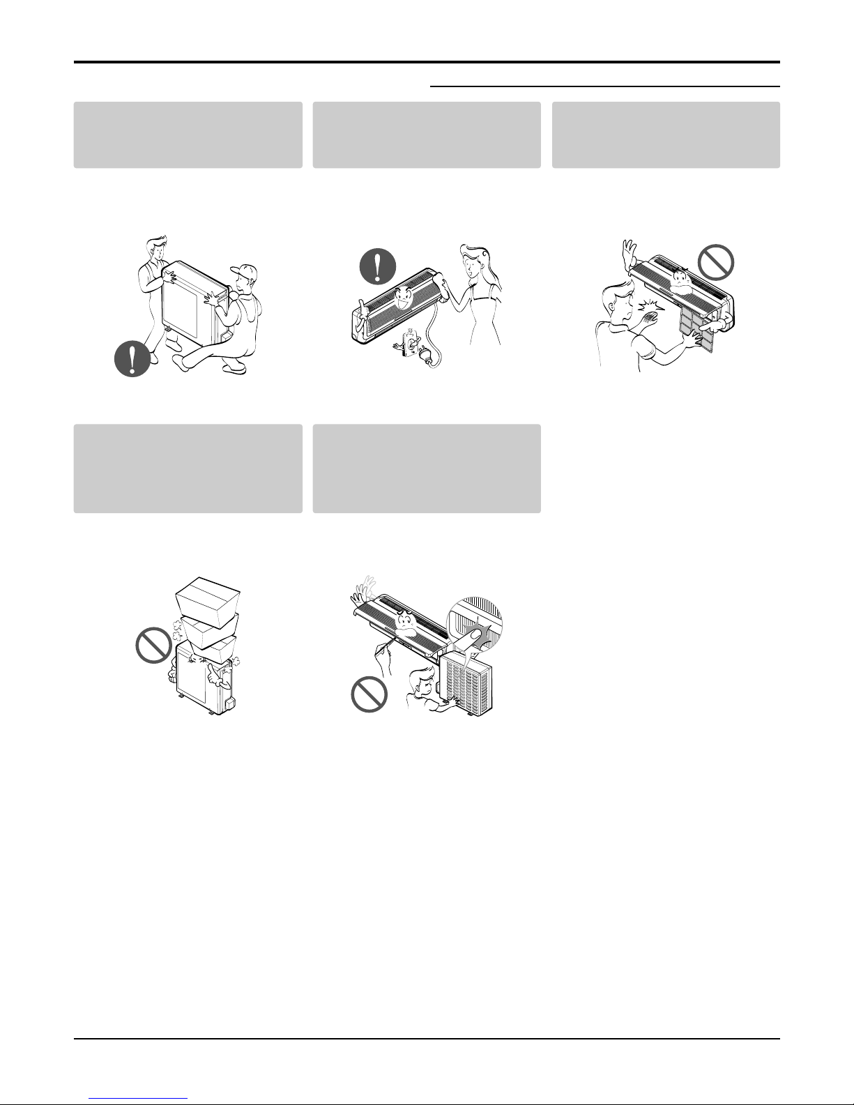
Safety Precautions..........................................................................................................................................5
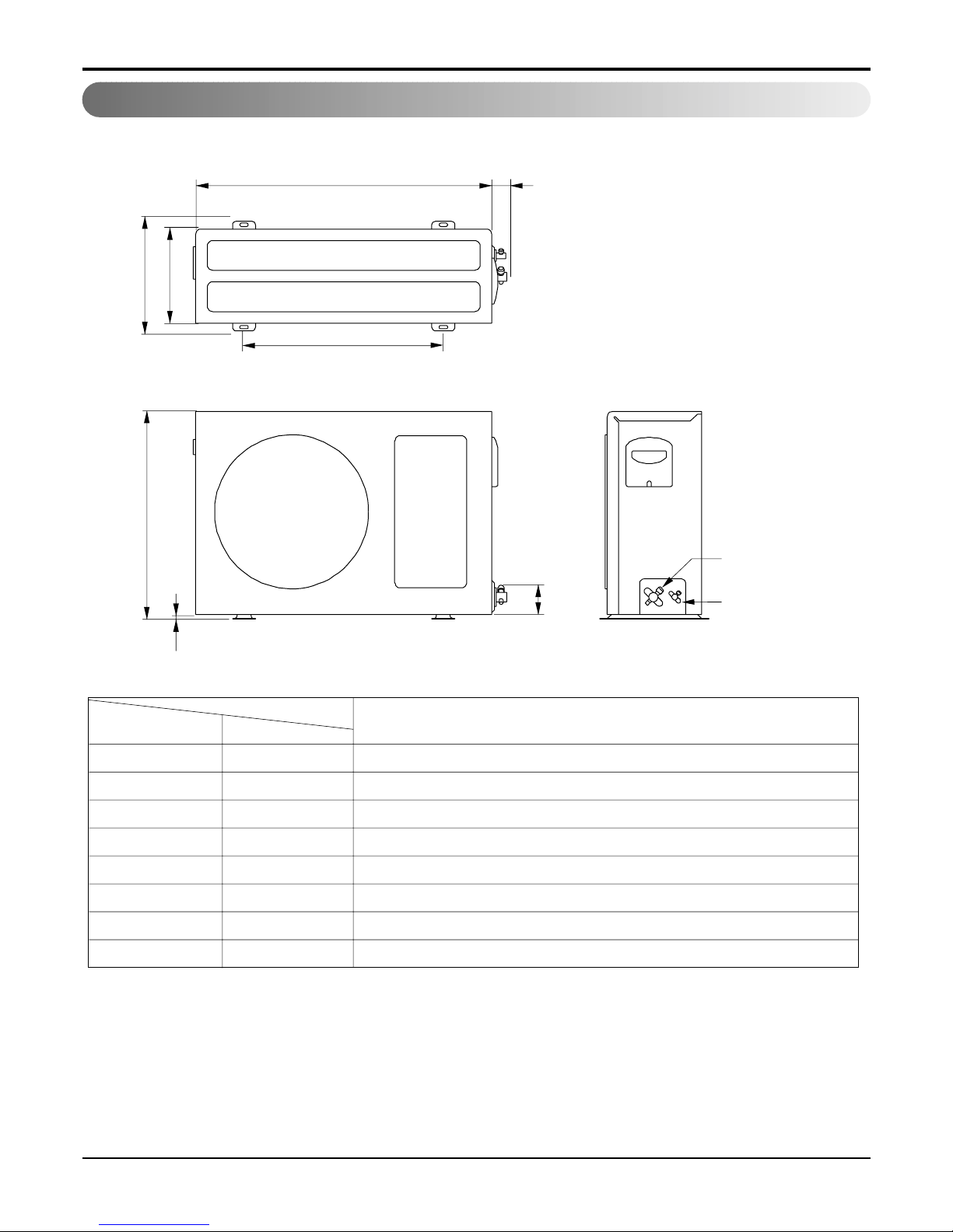
Dimensions .....................................................................................................................................................9
Symbols Used in this Manual.....................................................................................................................9
Indoor Unit..................................................................................................................................................9
Outdoor Unit.............................................................................................................................................10
Product Specifications ................................................................................................................................12
Installation.....................................................................................................................................................14
Select the Best Location .........................................................................................................................14
Piping Length and Elevation.....................................................................................................................14
How to Fix Installation Plate.....................................................................................................................15
Drill a Hole in the Wall..............................................................................................................................15
Installation Instructions of Telephone Control(Optional)...........................................................................15
Flaring Work.............................................................................................................................................16
Connection of Piping Indoor.....................................................................................................................17
Connection of the Pipes-Outdoor.............................................................................................................20
Connect the Cable to the Indoor Unit.......................................................................................................21
Connect the Cable to the Outdoor Unit....................................................................................................22
Checking the Drainage.............................................................................................................................23
Form the Piping........................................................................................................................................23
Air Purging ...............................................................................................................................................24
Air Purging with Vacuum Pump................................................................................................................24
Test Running ............................................................................................................................................26
Functions ......................................................................................................................................................27
Operation ......................................................................................................................................................30
Disassembly ..................................................................................................................................................45
Indoor Unit................................................................................................................................................45
Schematic Diagram.......................................................................................................................................48
Electric Control device..............................................................................................................................48
Wiring Diagram.........................................................................................................................................51
Components Location ..............................................................................................................................53
Troubleshooting Guide.................................................................................................................................57
Refrigeration Cycle Diagram....................................................................................................................57
Pipe Length and the Elevation .................................................................................................................58
2-way, 3-way Valve...................................................................................................................................59
Cycle Parts...............................................................................................................................................66
Self-diagnosis Function............................................................................................................................67
Electronic Parts........................................................................................................................................69
Exploded View ..............................................................................................................................................80
Indoor Unit................................................................................................................................................80
Outdoor Unit.............................................................................................................................................81
Replacement Parts List ................................................................................................................................82
Indoor.......................................................................................................................................................82
Outdoor ....................................................................................................................................................83

Service Manual 3
LG Model Name
12 -345678910
Code Type Code of Model Meaning
1 Producing Center, A~Z L: Chang-won R22 N: India
Refrigerant A: Chang-won R410A Z: Brazil
C: Chang-won R407C D: Indonesia
T: China
U: China R410A X: Mexico
K: Turkey R22
V: Vietnam E: Turkey R410A
S: Out Sourcing H: Thailand
2 Product Type A~Z S: Split Type Air Conditioner
3 Cooling/Heating/Inverter A~Z C: Cooling only
H: Heat pump
X: C/O + E/Heater
Z: H/P + E/Heater
V: AC Inverter C/O
N: AC Inverter H/P
Q: DC Inverter C/O
W: DC Inverter H/P
4, 5 Capacity 0~9 Cooling/Heating Capacity
Ex. "09" →9,000 Btu/h
6 Electric Range 1~9 1: 115V/60Hz, A: 220V, 50Hz, 3Phase
A~Z 2: 220V/60Hz B: 208~230V, 60Hz, 3Phase
3: 208-230V/60Hz C: 575V, 50Hz, 3Phase
5: 200-220V/50Hz D: 440~460, 60Hz, 3Phase
6: 220-240V/50Hz E: 265V, 60Hz
7: 110V, 50/60Hz F: 200V, 50/60Hz
8: 380-415V/50Hz
9: 380-415V/60Hz
7 Chassis A~Z Name of Chassis of Unit
Ex. LSP →SP Chassi
s
8 Look A~Z Look,
Color (Artcool Model)
9 Function A~Z
10 Serial No. 1~9 LG Model Development Serial No.
* ARTCOOL COLOR
Basic A
Basic+4Way B
Plasma Filter C
Plasma Filter+4 Way D
Tele+LCD E
Tele+LCD+Nano plasma+4Way F
Nano Plasma F+(A/changeove)+A/clean+Low A G
Nano Plasma F+(A/changeove)+A/clean+4way+Low A H
Tele+LED+4way I
Internet J
Plasma F+4Way+Oxy generator K
Nano Plasma F+(A/changeove)+A/clean L
Nano Plasma F+(A/changeove)+A/clean+4way M
Nano Plasma F+(A/changeove)+A/clean+PTC N
Nano Plasma F+(A/changeove)+Autoclean+4way+PTC P
Nano Plasma F+(A/changeove)+A/clean+4way+Low A+PTC Q
Negative ION+A/Clean R
(Nano)Plasma+Negative ION+A/Clean S
4way+(Nano)Plasma F+Negative ION+Healthy dehumidification+A/Clean
T
Nano Plasma F+4Way+(A/changeove)+A/clean+Oxy generator U
4way+(Nano)Plasma F+Negative ION+Healthy dehumidification+A/Clean+Oxy generator
V
Dry Contact W
Wired Remocon 8
R Mirror
W White
B Blue
D Wood
M Metal
C Cherry
N Walnut
A Gogh
S Sisley
Q Quran
K Mecca
CHASSIS Look
D
K
L
G
M
N
D
P
Division
Panel Type(Deluxe)
Fighting 'Look'
(LG1)
(LG2)-SEMI PANEL
OEM1
OEM2
Panel Type(Deluxe)
LG3
S4/S5
S6
SQ
SR
ST
2003~

4Room Air Conditioner
12 -345678910
Code Type Code of Model Meaning
1 Producing Center, A~Z L: Chang-won R22 N: India
Refrigerant A: Chang-won R410A Z: Brazil
C: Chang-won R407C D: Indonesia
T: China M: Mexico
K: Turkey R22 V: Vietnam
E: Turkey R410A S: Out Sourcing
H: Thailand
2 Product Type A~Z S: Split Type Air Conditioner
3 Cooling/Heating/Inverter A~Z C: Cooling only
H: Heat pump
X: C/O + E/Heater
Z: H/P + E/Heater
V: AC Inverter C/O
N: AC Inverter H/P
Q: DC Inverter C/O
W: DC Inverter H/P
4, 5 Capacity 0~9 Cooling/Heating Capacity
Ex. "09" →9,000 Btu/h
6 Electric Range 1~9 1: 115V/60Hz, A: 220V, 50Hz, 3Phase
A~Z 2: 220V/60Hz B: 208~230V, 60Hz, 3Phase
3: 208-230V/60Hz C: 575V, 50Hz, 3Phase
5: 200-220V/50Hz D: 440~460, 60Hz, 3Phase
6: 220-240V/50Hz E: 265V, 60Hz
7: 110V, 50/60Hz F: 200V, 50/60Hz
8: 380-415V/50Hz
9: 380-415V/60Hz
7 Chassis A~Z Name of Chassis of Unit
Ex. LSP →SP Chassis
8 Look A~Z Look,
Color (Artcool Model)
9 Function A~Z
10 Serial No. 1~9 LG Model De
* ARTCOOL COLOR
velopment Serial No.
Basic A
Basic+4Way B
Plasma Filter C
Plasma Filter+4 Way D
Tele+LCD E
Tele+LCD+Nano plasma+4Way F
Nano Plasma F+(A/changeove)+A/clean+Low A G
Nano Plasma F+(A/changeove)+A/clean+4way+Low A H
Tele+LED+4way I
Internet J
Plasma F+4Way+Oxy generator K
Nano Plasma F+(A/changeove)+A/clean L
Nano Plasma F+(A/changeove)+A/clean+4way M
Nano Plasma F+(A/changeove)+A/clean+PTC N
Nano Plasma F+(A/changeove)+Autoclean+4way+PTC P
Nano Plasma F+(A/changeove)+A/clean+4way+Low A+PTC Q
Negative ION+A/Clean R
(Nano)Plasma+Negative ION+A/Clean S
4way+(Nano)Plasma F+Negative ION+Healthy dehumidification+A/Clean
T
Nano Plasma F+4Way+(A/changeove)+A/clean+ U
R Mirror
W White
B Blue
D Wood
M Metal
C Cherry
2003

Service Manual 5
Safety Precautions
Safety Precautions
To prevent injury to the user or other people and property damage, the following instructions must
be followed.
■Incorrect operation due to ignoring instruction will cause harm or damage. The seriousness is
classified by the following indications.
■Meanings of symbols used in this manual are as shown below.
This symbol indicates the possibility of death or serious injury.
This symbol indicates the possibility of injury or damage to properties only.
Be sure not to do.
Be sure to follow the instruction.
Do not use damaged power
cords, plugs, or a loose socket.
• There is risk of fire or electric
shock.
Always use the power plug
and socket with the ground
terminal.
• There is risk of electric shock.
Install the panel and the cover
of control box securely.
• There is risk of fire or electric
shock.
■Installation
Do not modify or extend the
power cord.
• There is risk of fire or electric
shock.
Do not install, remove, or re-
install the unit by yourself
(customer).
• There is risk of fire, electric shock,
explosion or injury.
Be cautious when unpacking
and installing the product.
• Shape edges could cause injury.
Be especially careful of the sharp
edges.

6Room Air Conditioner
Safety Precautions
For installation, always con-
tact the dealer or an
Authorized Service Center.
• There is risk of fire, electric shock,
explosion, or injury.
Do not install the product on a
defective installation stand.
• It may cause injury, accident, or
damage to the
product.
Be sure the installation area
does not deteriorate with age.
• If the base collapses, the air condi-
tioner could fall with it, causing
property damage, product failure,
and personal injury.
Do not let the air conditioner
run for a long time when the
humidity is very high and a
door or a window is left open.
• Moisture may condense and wet or
damage furnishings.
Always install a dedicated
circuit and breaker.
• Improper wiring or installation may
cause fire or electric shock
Use the correctly rated break-
er or fuse.
• There is risk of fire or electric
shock.
■Operation
Do not turn the air-conditioner
ON or OFF by plugging or
unplugging the power plug.
• There is risk of fire or electric
shock.
Use a dedicated outlet for this
appliance.
• There is risk of fire or electric
shock.
Grasp the plug to remove the
cord from the outlet. Do not
touch it with wet hands.
• There is risk of fire or electric
shock.

Service Manual 7
Safety Precautions
■Installation
Unplug the unit if strange
sounds odors, or smoke
comes from it.
• There is risk of fire, failure of the
product, and/or electric shock.
Do not open the inlet grill of the
product during operation. (Do
not touch the electrostatic filter,
if the unit is so equipped.)
• There is risk of physical injury,
electric shock, or product.
Be cautious that water could
not enter the product.
• There is risk of fire, electrical shock
or product damage.
Do not place a heater or other
appliances near the power
cable.
• There is risk of fire, failure of the
product, and/or electric shock.
Do not allow water to run into
electric part.
• There is risk of fire, failure of the
product, and/or electric shock.
Do not store of use flammable
gas or combustibles near the
air conditioner.
• There is risk of fire or failure of
product.
Wax
Thinner
Always check for gas(refriger-
ant) leakage after installation
or repair of product.
• Low refrigerant levels may cause
failure of product.
Install the drain hose to
ensure that water is drained
away properly.
• A bad connection may cause water
leakage.
Keep level even when
installing the product.
• To avoid vibration or water leak-
age.
90˚

Safety Precautions
8Room Air Conditioner
■Operation
Use two or more people to lift
and transport the air condi-
tioner
•Avoid personal injury.
Use a soft cloth to clean. Do
not use harsh detergents, sol-
vents, etc.
•There is risk of fire, electric shock
or damage to the plastic parts of
the product.
Do not touch the metal parts of
the product when removing the
air filter. They are very sharp!
•There is risk of personal injury.
Do not step on or put anything
on the product. (outdoor unit)
•There is risk of personal injury and
failure of product.
Do not insert hands or other
objects through the air inlet or
outlet while the air conditioner
is plugged in.
•There are sharp and moving parts
that could cause personal injury.

Service Manual 9
Dimensions
Dimensions
Installation plate
D
H
W
W mm 824 900 1090
H mm 260 285 314
D mm 155 156 172
Model
Dimension
AS-W096QGG1 AS-W126RGH1 AS-W186TGH1
AS-W246TGH1
Indoor Unit
This symbol alerts you to the risk of electric shock.
This symbol alerts you to hazards that could cause harm to the
air conditioner.
This symbol indicates special notes.
NOTICE
Symbols Used in this Manual

10 Room Air Conditioner
Outdoor Unit
Dimensions
WL2
L3
L1
D
H
L4
L5
Gas side
(3-way valve)
Liquid side
(2-way valve)
MODEL
DIM unit
W mm 770
H mm 540
D mm 245
L1 mm 285
L2 mm 65
L3 mm 518
L4 mm 10
L5 mm 100
AS-W096QGG1
AS-W126RGH1

Service Manual 11
Dimensions
Outdoor Unit
W
L7 L6 L8 L9
D
L1
L2
L3
L10
L4L5
H
Gas side
Liquid side
AS-W186TGH1
AS-W246TGH1
AS-W246TLG1
W mm 870
H mm 655
D mm 320
L1 mm 370
L2 mm 340
L3 mm 25
L4 mm 630
L5 mm 25
L6 mm 546
L7 mm 162
L8 mm 162
L9 mm 54
L10 mm 74.5
MODEL
DIM

12 Room Air Conditioner
Product Specifications
Table-1
Model Name
Item Unit
W
MIN kcal/h.(W)
Btu/h.
W
Cooling Capacity Type kcal/h.(W)
Btu/h.
W
Max kcal/h.(W)
Btu/h.
W
MIN kcal/h.(W)
Btu/h.
W
Heating Capacity Type kcal/h.(W)
Btu/h.
W
Max kcal/h.(W)
Btu/h.
IN:20°C,Out: -10°C(Heater ON)
Btu/h.
IN:20°C,Out: -10°C(Heater OFF)
Btu/h.
Power Input Cooling W
Heating W
Heating(-10°C,Heater ON)
W
Heating(-10°C,Heater OFF)
W
Running Current Cooling A
Heating A
Heating(-10°C,Heater ON)
A
Heating(-10°C,Heater OFF)
A
Starting Current Cooling A
Heating A
EER Cooling W/W
Btu/h.W
COP Heating W/W
Power Supply Ø,V,Hz
Power Factor %
Air Circulation Indoor,Max m3/min(CFM)
Outdoor,Max m3/min(CFM)
Moisture Removal l/h.(pts/h.)
Noise Level Indoor,High dB(A)±3
(Sound Med. dB(A)±3
Pressure,1m) Low dB(A)±3
Outdoor,Max dB(A)±3
Refrigerant(R410A)Charge g
Power Cord AWG#:P*mm2
Connecting Cable AWG#:P*mm2
Connecting Tube Liquid Side mm(in)
(Ø. Socket Flare) Gas Side mm(in)
Length,std m(in)
Drain Hose (O.D , I.D) mm(in)
Indoor mm
Dimension inch
(W*H*D) Outdoor mm
inch
Net Weight Indoor kg(lbs)
Outdoor kg(lbs)
AS-W096QGG1 AS-W126RGH1 AS-W186TGH1 AS-W246TGH1
Product Specifications
1,582 2,110 1,758 4,249
1,361 1,814 1,512 3,654
5,400 7,200 6,000 14,500
2,640 3,520 5,280 7,032
2,270 3,027 4,540 6,048
9,010 12,014 18,016 24,000
2,901 3,868 5,801 7,735
2,495 3,326 4,990 6,653
9,900 13,200 19,800 26,400
1,978 2,532 1,406 3,604
1,701 2,177 1,210 3,100
6,750 8,640 4,800 12,300
3,170 3,960 6,070 7,735
2,726 3,405 5,219 6,653
10,819 13,512 20,711 26,400
3,481 4,351 6,651 8,497
2,994 3,742 5,720 7,308
11,880 14,850 22,700 29,000
----
----
950 1,200 1,630 2,480
1,150 1,300 1,900 2,730
----
----
4.3 5.4 7.5 11.5
5.1 5.7 8.6 12.5
----
----
4.3 5.4 7.5 11.5
5.1 5.7 8.6 12.5
2.78 2.93 3.24 2.84
9.48 10.01 11.06 9.68
2.76 3.05 3.19 2.83
1,220-240,50 1,220-240,50 1,220-240,50 1,220-240,50
97 97 97 97
7.2(254) 8.70(307) 13.0(459) 16.0(565)
26(918) 26(918) 42(1483) 45(1589)
1.4(2.94) 1.5(3.2) 2.12(4.48) 2.90(6.13)
35 40 42 47
32 37 39 43
29 31 36 39
48 48 55 58
610 810 1180 1500
16:3*1.0 16:3*1.5 12:3*2.5 12:3*2.5
16:4*1.0 16:4*1.5 12:4*2.5 12:4*2.5
6.35(1/4) 6.35(1/4) 6.35(1/4) 9.52(3/8)
9.52(3/8) 12.7(1/2) 12.7(1/2) 15.88(5/8)
7.5(295) 7.5(295) 7.5(295) 7.5(295)
21.5,16.0(0.85,0.63) 21.5,16.0(0.85,0.63) 21.5,16(0.85,0.63) 21.5,16(0.85,0.63)
824*260*155 900*285*156 1090*314*172 1090*314*172
32.4*10.2*6.1 35.1*11.1*6.2 42.9*12.4*6.8 42.9*12.4*6.8
770*540*245 770*540*245 870*655*320 870*655*320
30.3*21.3*9.6 30.3*21.3*9.6 34.3*25.8*12.6 34.3*25.8*12.6
7.0(15.4) 9.5(20.9) 12(26.5) 12(26.5)
34(74.8) 38(83.8) 60(132.3) 65(143.3)

Service Manual 13
Product Specifications
Table-2
Model Name
Item Unit
W
MIN kcal/h.(W)
Btu/h.
W
Cooling Capacity Type kcal/h.(W)
Btu/h.
W
Max kcal/h.(W)
Btu/h.
W
MIN kcal/h.(W)
Btu/h.
W
Heating Capacity Type kcal/h.(W)
Btu/h.
W
Max kcal/h.(W)
Btu/h.
IN:20°C,Out: -10°C(Heater ON)
Btu/h.
IN:20°C,Out: -10°C(Heater OFF)
Btu/h.
Power Input Cooling W
Heating W
Heating(-10°C,Heater ON)
W
Heating(-10°C,Heater OFF)
W
Running Current Cooling A
Heating A
Heating(-10°C,Heater ON)
A
Heating(-10°C,Heater OFF)
A
Starting Current Cooling A
Heating A
EER Cooling W/W
Btu/h.W
COP Heating W/W
Power Supply Ø,V,Hz
Power Factor %
Air Circulation Indoor,Max m3/min(CFM)
Outdoor,Max m3/min(CFM)
Moisture Removal l/h.(pts/h.)
Noise Level Indoor,High dB(A)±3
(Sound Med. dB(A)±3
Pressure,1m) Low dB(A)±3
Outdoor,Max dB(A)±3
Refrigerant(R410A)Charge g
Power Cord AWG#:P*mm2
Connecting Cable AWG#:P*mm2
Connecting Tube Liquid Side mm(in)
(Ø. Socket Flare) Gas Side mm(in)
Length,std m(in)
Drain Hose (O.D , I.D) mm(in)
Indoor mm
Dimension inch
(W*H*D) Outdoor mm
inch
Net Weight Indoor kg(lbs)
Outdoor kg(lbs)
AS-W246TLG1
4249
3654
14500
7032
6048
24000
7735
6653
26400
3604
3100
12300
7735
6653
26400
8497
7308
29000
-
-
2320
2400
-
-
11.5
12.5
-
-
11.5
12.5
2.61
10.34
3.22
1,220-240,50
97
16.0(565)
42(1589)
2.9
45
-
37
56
1500
12:3*2.5
12:4*2.5
9.52(3/8)
15.88(5/8)
7.5(295)
21.5,16(0.85,0.63)
1090*314*172
42.9*12.4*6.8
870*655*320
34.3*25.8*12.6
12(26.5)
60(132.3)

14 Room Air Conditioner
Installation
Installation
Indoor unit
•Do not have any heat or steam near the unit.
•Select a place where there are no obstacles in
front of the unit.
•Make sure that condensation drainage can be con-
veniently routed away.
Do not install near a doorway.
•Ensure that the space around the left and right of
the unit is more than "A". The unit should be
installed as high on the wall as possible, allowing a
minimum of "B" from ceiling.
•Use a stud finder to locate studs to prevent unnec-
essary damage to the wall.
Outdoor unit
•If an awning is built over the unit to prevent direct
sunlight or rain exposure, make sure that heat
radiation from the condenser is not restricted.
•Ensure that the space around the back and sides
is more than 10cm. The front of the unit should
have more than 70cm of space.
•Do not place animals and plants in the path of the
warm air.
•Take the air conditioner weight into account and
select a place where noise and vibration are mini-
mum.
•Select a place so that the warm air and noise from
the air conditioner do not disturb neighbors.
More than "A"
More than B
More than 2.3m More than "B"
More than 10cm More than 10cm
More
than 60cm
More than 60cm
More than 70cm
CAUTION: Install the indoor unit on the wall
where the height from the floors more than 2.3
meters.
CAUTION:
• Capacity is based on standard length and maximum
allowance length is on the basis of reliability.
• Oil trap should be installed every 5~7 meters.
Grade Clearance(cm)
AB
7K~28K 10 5
30K~38K 30 12
Pipe Size
Capacit
y
(Btu/h) GAS LIQUID
Max.
Length
A (m)
Additional
Refrigerant
(g/m)
Max.
Elevation
B(m)
Standard
Length
(m)
7k~14k 3/8"(Ø9.52) 1/4"(Ø6.35) 4 or 7.5 7 15 20
1/2"(Ø12.7) 1/4"(Ø6.35) 4 or 7.5 7 15 20
1/2"(Ø12.7) 1/4"(Ø6.35) 4 or 7.5 15 30 20
18k~28k 5/8"(Ø15.88) 1/4"(Ø6.35) 4 or 7.5 15 30 20
5/8"(Ø15.88) 3/8"(Ø9.52) 4 or 7.5 15 30 30
30k~38k 5/8"(Ø15.88) 3/8"(Ø9.52) 7.5 15 30 30
3/4"(Ø19.05) 3/8"(Ø9.52) 7.5 15 30 50
If case more than 5m
Outdoor unit
Indoor unit
Outdoor unit
Indoor unit
A
Oil trap
Outdoor unit
Indoor unit
B
I
Selection of the Best Location
Piping Length and Elevation

Service Manual 15
Installation
The wall you select should be strong and solid
enough to prevent vibration
1. Mount the installation plate on the wall with four
type A screws. If mounting the unit on a concrete
wall, use anchor bolts.
•Mount the installation plate horizontally by aligning
the centerline using a level.
2. Measure the wall and mark the centerline. It is
also important to use caution concerning the
location of the installation plate-routing of the
wiring to power outlets is through the walls typi-
cally. Drilling the hole through the wall for pip-
ing connections must be done safely.
•Drill the piping hole with a ø70mm hole core drill.
Drill the piping hole at either the right or the left
with the hole slightly slanted to the outdoor side.
•Open the Front Grille.
•Pass Telephone Control Cord Wire through the
hole which the power cord goes through.
•Connect Telephone Control Cord Wire to the
phone jack of telephone PCB of Control Box.
•Fix Telephone Control Cord Wire inside Control
box so as not to disconnect.
•Close the Front Grille.
Installation Plate
Type "A" screw
5-7mm
(3/16"~5/16")
Indoor WALL Outdoor
Answering telephone / Normal telephone
(Not packed in the box)
Adaptor
(Not packed in
the box)
Telephone Control
Cord Wire
(Packed in the box)
Phone
Conductor
Installation plate
Ø70mm
Left rear piping Right rear piping
C
D
B
AØ70mm
Ø70mm
Left rear piping Right rear piping
CE A
B
D
Installation plateInstallation plate
ABCD
SJ 90 20 80 20
SL, SK 45 40 80 20
SQ 75 12 80 12
SR 0 40 20 40
ST 105 0 210 0
CHASSIS
(Grade)
Distance (mm)
How to Fix Installation Plate Drill a Hole in the Wall
Installation Instructions of Telephone Control(Optional)
ABCDE
SM 180 115 - 115 50
SN 180 115 195 115 -
CHASSIS
(Grade)
Distance (mm)

16 Room Air Conditioner
Installation
Flaring Work
Main cause for refrigerant leakage is due to defect in
the flaring work. Carry out correct flaring work using the
following procedure.
Cut the pipes and the cable.
•Use the piping kit accessory or pipes purchased
locally.
•Measure the distance between the indoor and the
outdoor unit.
•Cut the pipes a little longer than the measured
distance.
•Cut the cable 1.5m longer than the pipe length.
Burr removal
•Completely remove all burrs from the cut cross
section of pipe/tube.
•Put the end of the copper tube/pipe in a downward
direction as you remove burrs in order to avoid
dropping burrs into the tubing.
Putting nut on
•Remove flare nuts attached to indoor and outdoor
unit, then put them on pipe/tube having completed
burr removal.
(not possible to put them on after flaring work)
Flaring work
•Firmly hold copper pipe in a die in the dimension
shown in the table above.
•Carry out flaring work using flaring tool as shown
below.
Check
•Compare the flared work with figure below.
•If flare is noted to be defective, cut off the flared
section and re-flare it.
Copper
pipe
90°Slanted Uneven Rough
Bar
Copper pipe
Clamp handle Red arrow mark
Cone
Yoke
Handle
Bar
"A"
Inclined
Inside is shiny without scratches
Smooth all round
Even length
all round
Surface
damaged Cracked Uneven
thickness
= Improper flaring =
Pipe Reamer
Point down
Flare nut
Copper tube
mm inch mm
Ø6.35 1/4 0~0.5
Ø9.52 3.8 0~0.5
Ø12.7 1/2 0~0.5
Ø15.88 5/8 0~1.0
Ø19.05 3/4 1.0~1.3
Outside diameter A

Service Manual 17
Installation
Connection of Piping Indoor
•Preparing the indoor unit's piping and drain hose
for installation through the wall.
•Remove the plastic tubing retainer(see illustration
below) and pull the tubing and drain hose away
from chassis.
•Replace the plastic tubing holder in the original
position.
For right rear piping
1. Route the indoor tubing and the drain hose in
the direction of rear right.
2. Insert the connecting cable into the indoor unit
from the outdoor unit through the piping hole.
•Do not connect the cable to the indoor unit.
•Make a small loop with the cable for easy
connection later.
3. Tape the tubing, drain hose, and the connecting
cable. Be sure that the drain hose is located at
the lowest side of the bundle. Locating at the
upper side can cause drain pan to overflow
inside the unit.
If the drain hose is routed inside the
room, insulate the hose with an insula-
tion material* so that dripping from
"sweating"(condensation) will not dam-
age furniture or floors.
*Foamed polyethylene or equivalent is recom-
mended.
4. Indoor unit installation
•Hook the indoor unit onto the upper portion of the
installation plate.(Engage the two hooks of the rear
top of the indoor unit with the upper edge of the
installation plate.) Ensure that the hooks are prop-
erly seated on the installation plate by moving it
left and right.
Press the lower left and right sides of the unit against the
installation plate until the hooks engage into their
slots(clicking sound).
4. Connecting the pipings to the indoor unit and
drain hose to drain pipe.
•Align the center of the pipes and sufficiently tight-
en the flare nut by hand.
NOTICE
CAUTION:
When
install, make sure
that the remaining
parts must be removed
clearly so as not to dam-
age the piping and drain
hose, especially power
cord and connecting cable.
Tubing holder
Connecting
cable
Loop
Gas side
piping
Liquid side
piping
Drain hose
Drain hose
Connecting
cable
Indoor unit tubing Flare nut Pipes
Drain hose

18 Room Air Conditioner
Installation
•Tighten the flare nut with a wrench.
•When extending the drain hose at the indoor unit,
install the drain pipe.
5. Wrap the insulation material around the con-
necting portion.
•Overlap the connection pipe insulation material
and the indoor unit pipe insulation material. Bind
them together with vinyl tape so that there is no
gap.
•Wrap the area which accommodates the rear pip-
ing housing section with vinyl tape.
•Bundle the piping and drain hose together by
wrapping them with vinyl tape for enough to cover
where they fit into the rear piping housing section.
For left rear piping
1. Route the indoor tubing and the drain hose to
the required piping hole position.
2. Insert the piping, drain hose, and the connecting
cable into the piping hole.
mm inch kg.m
Ø6.35 1/4 1.8
Ø9.52 3.8 4.2
Ø12.7 1/2 5.5
Ø15.88 5/8 6.6
Ø19.05 3/4 6.6
Outside diameter Torque
Wrench
Indoor unit tubing
Open-end wrench (fixed)
Connection pipe
Flare nut
Vinyl tape(narrow)
Adhesive
Drain pipe
Indoor unit drain hose
Plastic bands Insulation material
Vinyl tape(narrow)
Connection
pipe
Connecting cable
Vinyl tape
(wide) Wrap with vinyl tape
Indoor
unit pipe
Pipe
Drain hose
Connecting
cable
Drain pipe
Connecting cable

Service Manual 19
Installation
3. Insert the connecting cable into the indoor unit.
•Don't connect the cable to the indoor unit.
•Make a small loop with the cable for easy connec-
tion later.
4. Tape the drain hose and the connecting cable.
•Connecting cable
5. Indoor unit installation
•Hang the indoor unit from the hooks at the top of
the installation plate.
•Insert the spacer etc. between the indoor unit and
the installation plate and separate the bottom of
the indoor unit from the wall.
6. Connecting the pipings to the indoor unit and
the drain hose to drain pipe.
•Align the center of the pipes and sufficiently tight-
en the flare nut by hand.
•Tighten the flare nut with a wrench.
•When extending the drain hose at the indoor unit,
install the drain pipe.
7. Wrap the insulation material around the con-
necting portion.
•Overlap the connection pipe heat insulation and
the indoor unit pipe heat insulation material. Bind
them together with vinyl tape so that there is no
gap.
•Wrap the area which accommodates the rear pip-
ing housing section with vinyl tape.
mm inch kg.m
Ø6.35 1/4 1.8
Ø9.52 3.8 4.2
Ø12.7 1/2 5.5
Ø15.88 5/8 6.6
Ø19.05 3/4 6.6
Outside diameter Torque
Vinyl tape
Adhesive
Drain hose
Indoor unit drain hose
(narrow)
Plastic bands Insulation material
Vinyl tape(narrow)
Connection
pipe
Connecting cable
Indoor
unit piping
Pipe
Vinyl tape
(wide) Wrap with vinyl tape
Installation plate
Spacer
Indoor unit
8cm
Indoor unit tubing Flare nut Pipes
Wrench
Indoor unit tubing
Connection pipe
Flare nut
Open-end wrench (fixed)

20 Room Air Conditioner
Installation
•Bundle the piping and drain hose together by
wrapping them with cloth tape over the range with-
in which they fit into the rear piping housing sec-
tion.
8. Reroute the pipings and the drain hose across
the back of the chassis.
9. Set the pipings and the drain hose to the back of
the chassis with the tubing holder.
•Hook the edge of tubing holder to tap on chassis
and push the bottom of tubing holder to be
engaged at the bottom of chassis.
10. Indoor unit installation
•Remove the spacer.
•Ensure that the hooks are properly seated on the
installation plate by moving it left and right.
Press the lower left and right sides of the unit against the
installation plate until the hooks engage into their
slots(clicking sound).
1. Align the center of the pipings and sufficiently
tighten the flare nut by hand.
2. Finally, tighten the flare nut with torque wrench
until the wrench clicks.
•When tightening the flare nut with torque wrench,
ensure the direction for tightening follows the
arrow on the wrench.
mm inch kg.m
Ø6.35 1/4 1.8
Ø9.52 3/8 4.2
Ø12.7 1/2 5.5
Ø15.88 5/8 6.6
Ø19.05 3/4 6.6
Outside diameter Torque
Drain hose Vinyl tape(narrow)
Pipe
Wrap with
vinyl tape(wide)
Piping for
passage through
piping hole
Outdoor unit
Gas side piping
(Bigger diameter)
Liquid side
piping
(Smaller
diameter)
Torque wrench
Tubing holder
Drain hose
Connecting
cable
Connection of the Pipes-Outdoor
This manual suits for next models
4
Table of contents
Other LG Air Conditioner manuals
Popular Air Conditioner manuals by other brands

INVENTOR
INVENTOR U5MRSL32(2)-18 installation manual

Defy
Defy ELECTRO MECHANICAL CONTROLS operating instructions

Carrier
Carrier 42KY Installation, operation and maintenance instructions

AERMEC
AERMEC FCW 222V Installation and user manual

Mitsubishi Electric
Mitsubishi Electric MSZ-EF22VEW operating instructions

Rheem
Rheem A180CL25E installation instructions