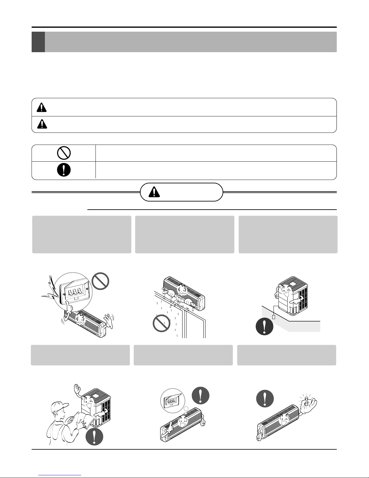
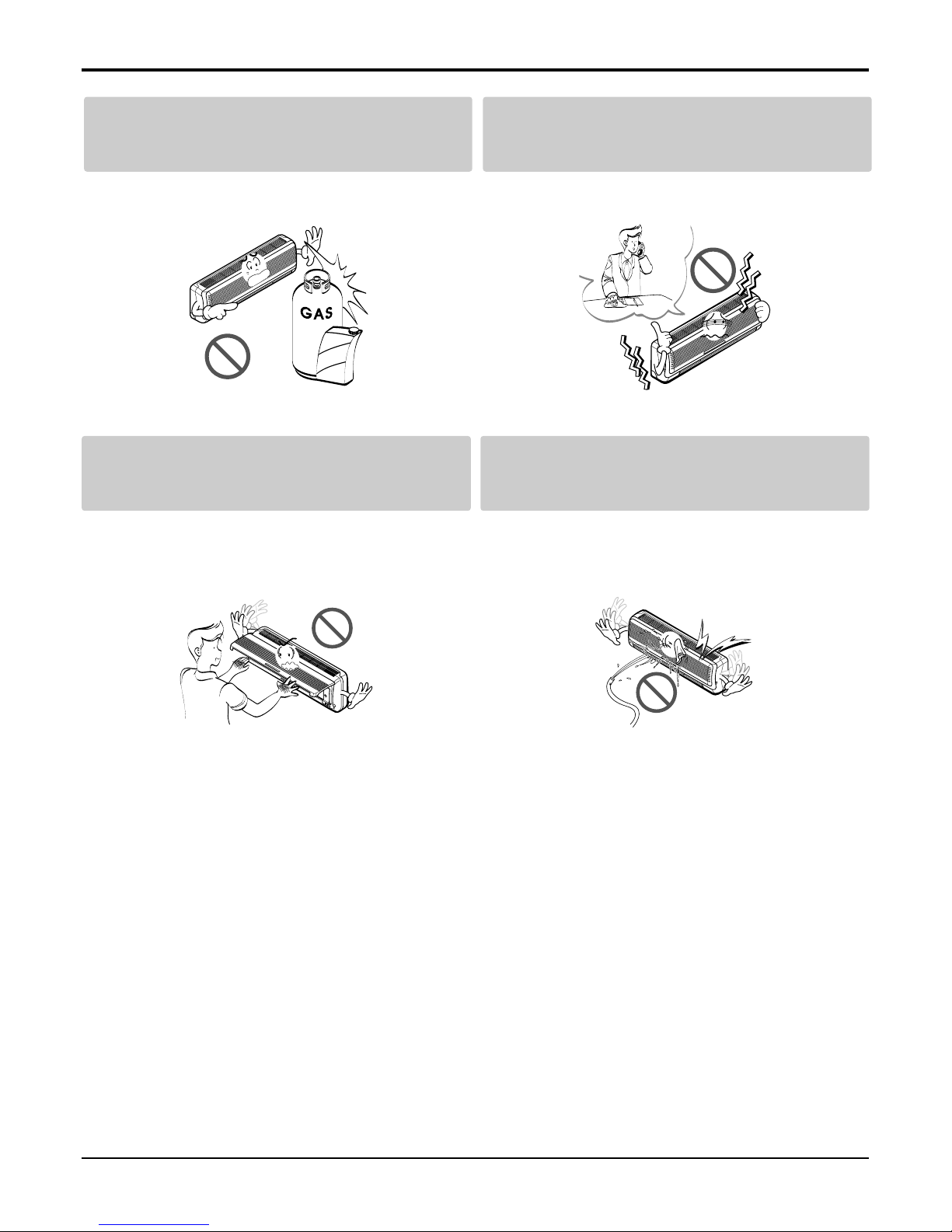
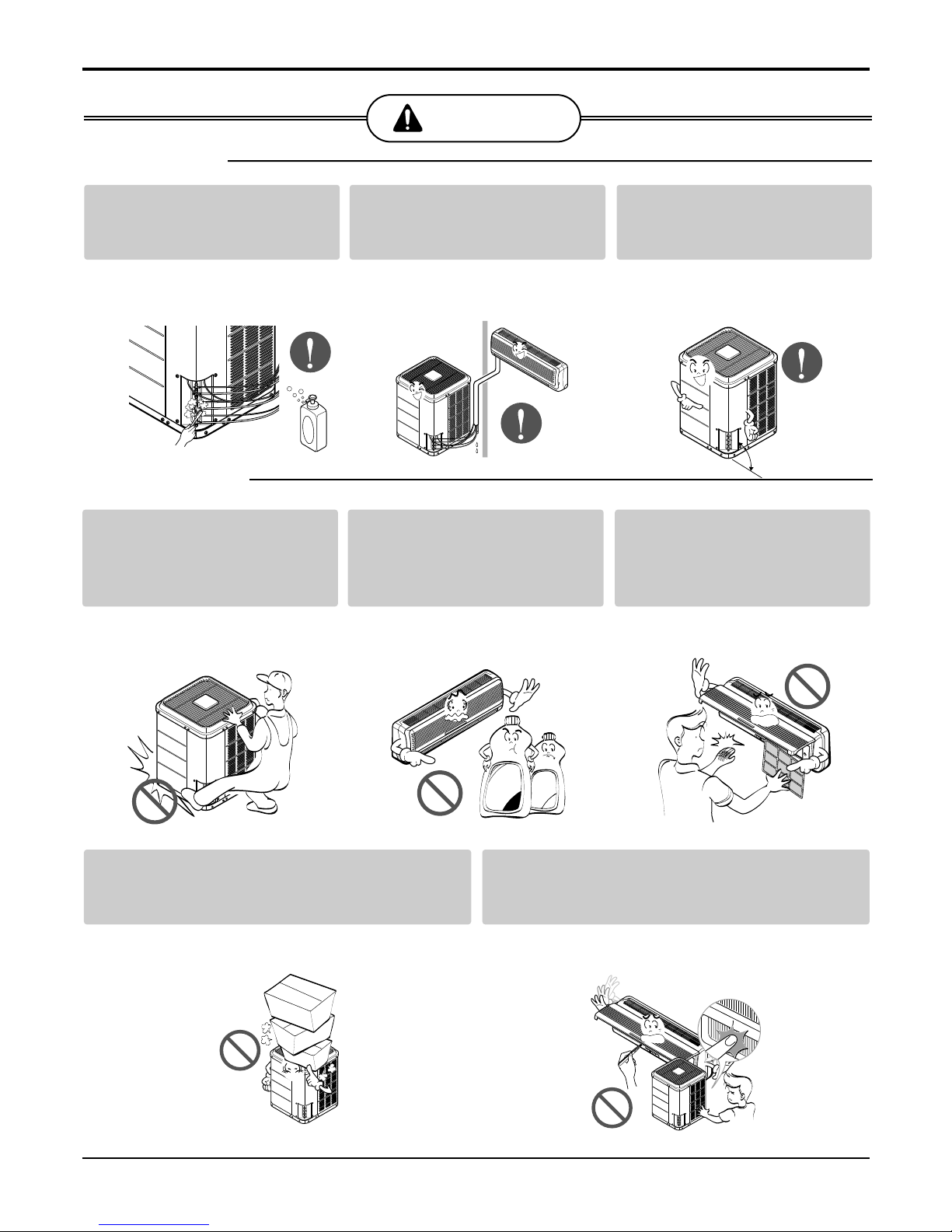
8Multi Type Air Conditioner
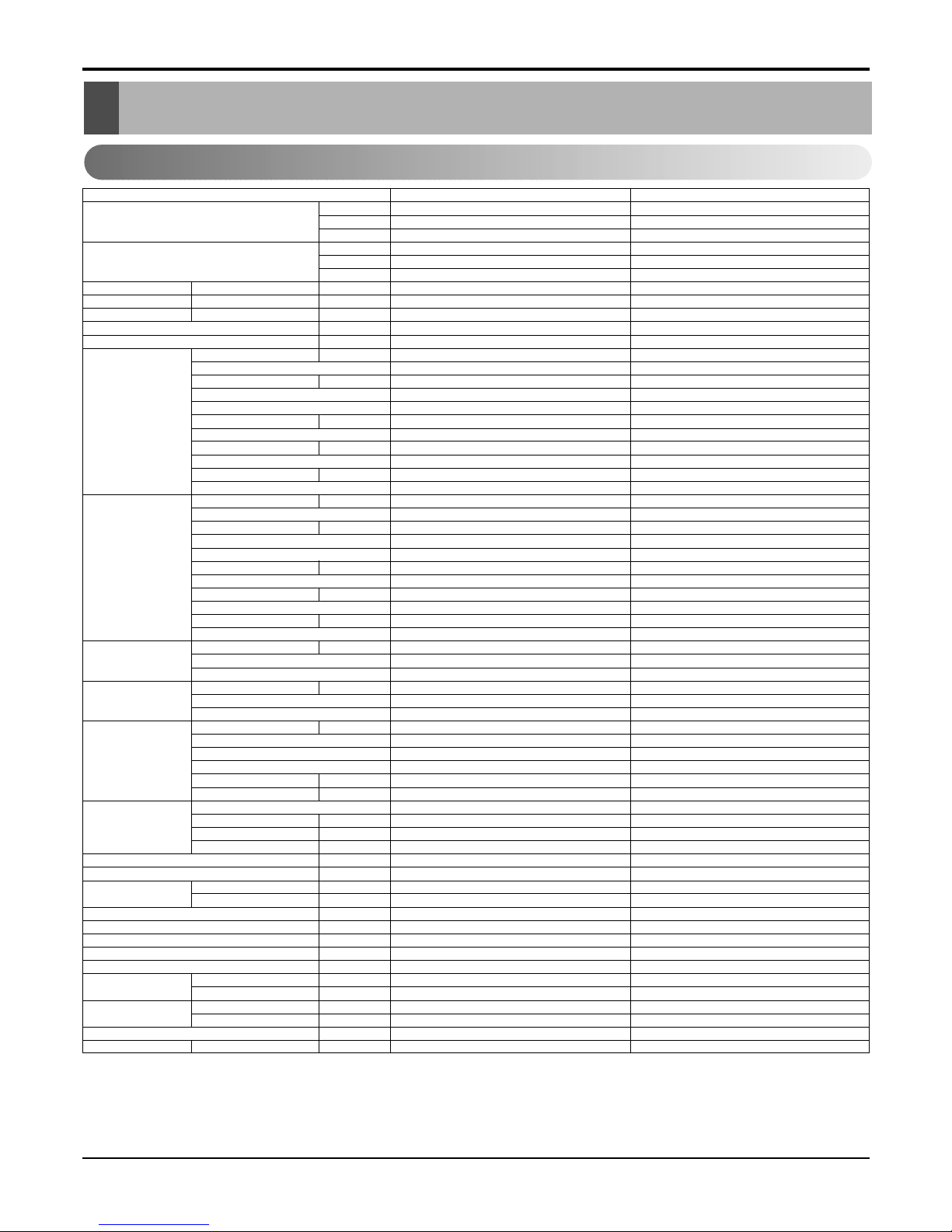
Product Specifications
Product Specifications
1. Outdoor
Notes:
1. Capacities are based on the following conditions:
Cooling: - Indoor Temperature 27°C(80.6°F) DB /19°C(66.2°F) WB
- Outdoor Temperature 35°C(95°F) DB /24°C(75.2°F) WB
- Interconnecting Piping Length 7.5m
- Level Difference of Zero.
2. Capacities are Net Capacities.
3. * : See Page "Combination Table"
Model
Cooling Capacity * kcal/h
W
Btu/h
Heating Capacity * kcal/h
W
Btu/h
Input * Cooling/Heating W
Running Current * Cooling/Heating A
Starting Current Cooling/Heating A
Power Supply Ø,V,Hz
Power Factor %
Compressor A Locked Rotor Amp. A
(TPS Cycle) Type
Quantity No
Model
Maker
Capacity kcal/h(Btu/h)
Motor Type
Motor Input W
Oil Type
Oil Charge cc
O.L.P Type(model name)
Compressor B Locked Rotor Amp. A
(Single Cycle) Type
Quantity No
Model
Maker
Capacity kcal/h(Btu/h)
Motor Type/Starting Type
Motor Input W
Oil Type
Oil Charge cc
O.L.P Type(model name)
Refrigerant Charge g(oz), type
Type
Control
Coil Tube Size (OD) inch(mm)
Fins per inch
No. of Rows & Column/No.
Fan Motor Output W
Model
No. of Poles
Input
Running Current A
Capacitor µF/Vac
Fan Type
No. Used / Diameter EA/inch(mm)
Discharge Side / Top
Speed rpm
Air Circulation CMM(CFM)
Noise Level(Sound Press,1m) dBA
SVC Valve Liquid inch(mm)
Gas inch(mm)
Drain(ID Ø)mm
Dimensions (W*H*D) inch(mm)
Net Weight kg(lbs)
Power Supply Cable No.* mm2
Interunit Cable No.* mm2
Max. Interunit Piping Total of Each Room m
Length For One Room m
Max. Installation Indoor Unit~Outdoor Unit m
Height Difference Indoor Unit~Indoor Unit m
Packing Dimension (W*H*D) inch(mm)
Stuffing Quantity Without S/Parts 20/40ft
L3UC482FA0 L3UH482FA0
3024~12096 3024~12096
3515~14067 3515~14067
12000~48000 12000~48000
- 3024~12096
- 3515~14067
- 12000~48000
1,460~5,360 1,460~5,360 / 1,540~5,640
6.8~24.7 6.8~24.7/ 7.1~26
--
1Ø, 220V, 60Hz 1Ø, 220V, 60Hz
98 98
35/26 35/26
Rotary Rotary
1/1 1/1
QJ208KAB/QK185KAF QJ208KAB/QK185KAF
LG/LG LG/LG
14650/12900 14650/12900
Single Phase Induction Motor / PSC Single Phase Induction Motor / PSC
1356/1205 1356/1205
ATMOS M60 or SUNISO 4GSI ATMOS M60 or SUNISO 4GSI
450/350 450/350
MRA98704~12026/MRA12070~12027 MRA98704~12026/MRA12070~12027
68 68
Rotary Rotary
11
QP348KD24B QP348KD24B
LG LG
25700 25700
Single Phase Induction Motor / PSC Single Phase Induction Motor / PSC
2424 2424
ATMOS M60 or SUNISO 4GSI ATMOS M60 or SUNISO 4GSI
700 700
Internal Internal
TPS Cycle : 1980(69.8) at 7.5m Single Cycle : 2140(75.5) at 7.5m TPS Cycle : 1980(69.8) at 7.5m Single Cycle : 2140(75.5) at 7.5m
R22 R22
L.E.V L.E.V
0.276(7.0) 0.276(7.0)
18 18
2R,36C 2R,36C
207 207
IC-13670 LG39F IC-13670 LG39F
66
340 340
1.5 1.5
6/400 6/400
Axial FAN Axial FAN
1/Ø20.7(526) 1/Ø20.7(526)
Top Discharge Top Discharge
1000 1000
80(2967) 80(2967)
60 60
1/4(6.35)*3EA 1/4(6.35)*3EA
1/2(12.7)*3EA 1/2(12.7)*3EA
--
28.0*32.6*27 (711 x 828 x 686) 28.0*32.6*27 (711 x 828 x 686)
120(264.5) 120(264.5)
3*4.5(Includes earth) 3*4.5(Includes earth)
4*0.75(Includes earth) 4*0.75(Includes earth)
50(TPS Cycle)+20(Single Cycle) 50(TPS Cycle)+20(Single Cycle)
30(TPS Cycle) 30(TPS Cycle)
30 15
7.5 7.5
33.5*35.0*30.1 (850 x 890 x 765) 33.5*35.0*30.1 (850 x 890 x 765)
40/84 40/84


 null")