LG LBNG3061YL User manual

Ceiling Duct Air Conditioner
SVC MANUAL(Exploded View)
MODEL : LBNG3061YL
LBUG3061YL
CAUTION
Before Servicing the unit, read the safety precautions in General SVC manual.
Only for authorized service personnel.
Internal Use Only
http://biz.lgservice.com
MODEL :

Contents
Functions .................................................................................................................................3
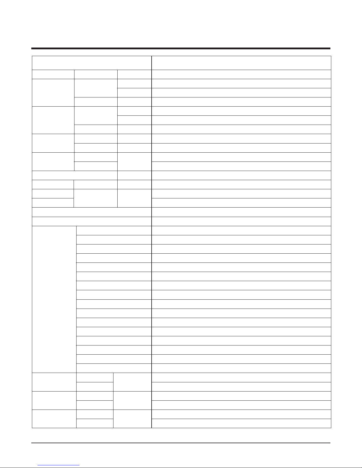
Product Specifications (Cooling & Heating)..........................................................................6
Dimensions ..............................................................................................................................7
Refrigeration Cycle Diagram ..................................................................................................8
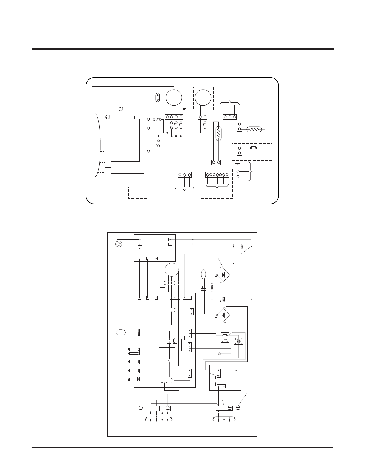
Wiring Diagram ........................................................................................................................9
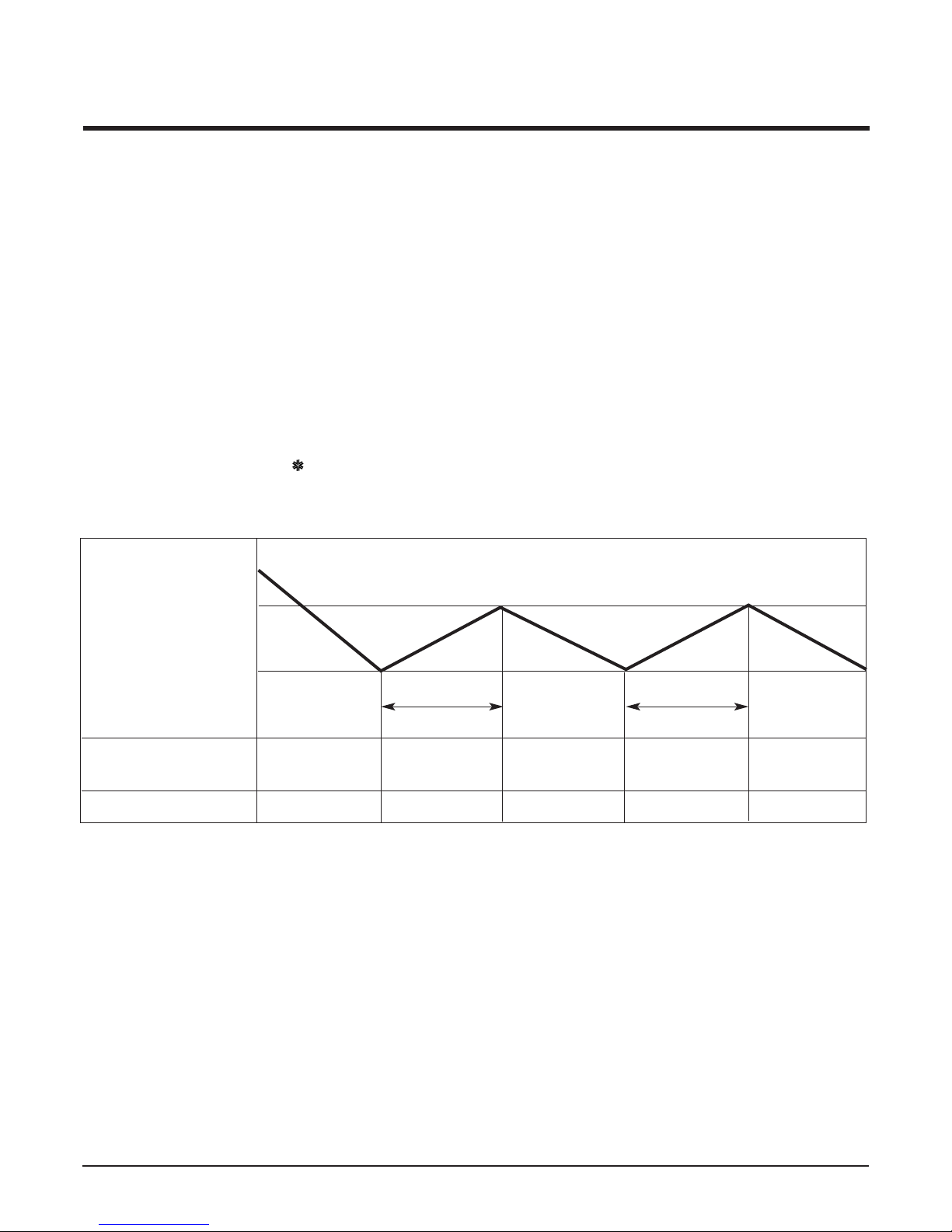
Operation Details ...................................................................................................................10
Installation of Indoor, Outdoor Unit .....................................................................................14
Test Running...........................................................................................................................23
Optional Operation ................................................................................................................25
Cycle........................................................................................................................................27
Cycle Troubleshooting Guide ..............................................................................................30
Electronic Parts Troubleshooting Guide .............................................................................31
Electronic Control Device .....................................................................................................44
Exploded View ........................................................................................................................48
- 2 -
Copyright ©2007 LG Electronics. Inc. All right reserved.
Only for training and service purposes LGE Internal Use Only

Functions
Indoor Unit
Operation ON/OFF by Remote controller
Sensing the Room Temperature
Room temperature control
Starting Current Control
Time Delay Safety Control
Indoor Fan Speed Control
Soft Dry Operation Mode
Auto Operation(Auto Change Over)
Deice (defrost) control (Heating)
Auto Restart
- 3 -
Copyright ©2007 LG Electronics. Inc. All right reserved.
Only for training and service purposes LGE Internal Use Only
Hot-start Control (Heating)
High head height Drain pump(Optional)
Central Control(Optional)
Group Control(Optional Wiring)
PLASMA (Optional)
Telephone Control Operation (Optional)
Radio Frequency Control Operation(Optional)
•
Maintains the room temperature in accordance with the Setting Temp.
• Indoor fan is delayed for 5 seconds at the starting.
• High, Med, Low
• Although the air-conditioner is turned off by a power failure, it is restarted automati-
cally previous operation mode after power supply.
• The setting temperature and desired operation mode are auto-
matically set by fuzzy rule.
• Both the indoor and outdoor fan stops during defrosting.
• Hot start after defrost ends.

- 4 -
Copyright ©2007 LG Electronics. Inc. All right reserved.
Only for training and service purposes LGE Internal Use Only
Outdoor Unit
Power relay control
Comp. Freq. control
Overheatng. Protection(Power module)
Freq. speed control(up/down speed)
V/F control
Total current control (over current protection)
DC peak current control
4 way valve control
Outdoor fan motor control
Discharge pipe temp. control
Overpressure protection
• If power is on, it will operate to chage capacitor on controller and power relay will operate after about
10sec.
• The final operating freq. of comp. is set the lowest freq. that limited outdoor temp., discharge pipe temp.,
target freq., owing to CT.
• It will be changed the drive voltage of comp. according to operating frequency.
• It is only operated in the heating operation mode except defrosting operation.
• High speed/Low speed

- 5 -
Copyright ©2007 LG Electronics. Inc. All right reserved.
Only for training and service purposes LGE Internal Use Only
Remote Controller
Operation ON/OFF
Operation Mode Selection
Fan Speed Selection
Room Temperature Display
Temperature Setting
Setting the Timer
Weekly Program
(Cooling
model only) (Heating
model only)
(Low) (Med) (High)
Cooling Operation Mode ( )
Heating Operation Mode ( ) Auto Operation Mode ( ) : Cooling model
Soft Dry Operation Mode ( )
Fan Operation Mode
Phase Control Setting
HI AUTOMEDLO
Auto change-over ( ) : Heating model
Program Holiday
SET/CLR
MinHour
Week
Timer CancelTimer Cancel
Timer
: High:39°C ↔LOW:11°C
: Fan Operates without cooling & heating
Cooling Heating
Down to 18°C
Up to 30°C
Down to 16°C
Up to 30°C

- 6 -
Copyright ©2007 LG Electronics. Inc. All right reserved.
Only for training and service purposes LGE Internal Use Only
Power Source Ø, V, Hz"
Cooling Capacity kcal/h(BTU/h)
W
Input W
Heating Capacity kcal/h(BTU/h)
W
Input W
Rated Load Amp. Cooling A
Heating A
Air Volumn Cooling(H/M/L) CMM(m3/min)
Heating(H/M/L)
Refrigerant(R-22) g
Drain Hose In. Dia mm
Main Cable No. X mm2
Connecting Cable
Remote Control Type
Refigerant Control Type
Fuction Soft Dry
Timer
Self Diagnosis
Deice Operation
Hot Start
Zone Control(Optional)
Central Control(Optional)
Group Control(Optional wiring)
Weekly Programning
2-Thermistor
Drain Pump (Optional)
Auto changeover(Auto Operation: CL)
Stand-by Consumption 0
Radio frequency control(Optional)
Tele Control(Optional)
PLASMA(Optional)
Connecting Pipe Liquid Inch
Gas (mm)
Dimension Indoor mm
Outdoor (WxDxH)
Net Indoor Kg
Weight Outdoor
1, 220-240, 50
7,600(30,000)
8,792
3,550
8,064(32,000)
9,378
2,900
17.5
14.0
26/22/18
26/22/18
1,600
22.6
3*5.5
4*0.75
L.C.D Wired
LEV
Yes
24 Hours On/Off
Yes
Yes
Yes
Optional
Optional
Yes
Yes
Yes
Optional
Yes
Yes
Optional
Optional
Optional
1/4(6.35)
5/8(15.88)
1180*450*298
870*320*800
35
72
Model
LB-G3061YL
Product Specifications (Cooling & Heating)

- 7 -
Copyright ©2007 LG Electronics. Inc. All right reserved.
Only for training and service purposes LGE Internal Use Only
Dimensions
W
H
D
(1) Indoor Unit
MODEL
DIM
W(mm) 1180
H(mm) 298
D(mm) 450
LBNG3061YL
H
W
D
MODEL
DIM
W(mm) 870
H(mm) 800
D(mm) 320
LBUG3061YL
(2) Outdoor Unit

Refrigeration Cycle Diagram
•
LB-G3061YL
• Rated performance for refrigerant line length of: 7.5m
• If it is installed at a distance of 15m, 300g of refrigerant should be added (15-7.5) x 40g = 300g
- 8 -
Copyright ©2007 LG Electronics. Inc. All right reserved.
Only for training and service purposes LGE Internal Use Only
INDOOR UNIT OUTDOOR UNIT
HEAT
EXCHANGER HEAT
EXCHANGER
LEV
COMPRESSOR
GAS PIPE
SENSOR
HEATING
SENSOR
DISCHARGE
PIPE SENSOR
GAS SIDE
LIQUID SIDE
COOLING
HEATING
REVERSING
VALVE
LIQUID PIPE
SENSOR
INDOOR
TEMPERATURE
SENSOR
LB-G3061YL 5/8" 1/4" 7.5 15 7.5 12.5 40
*Additional
refrigerant
(g/m)
Pipe size(Diameter: ø) Piping length(m) Elevation(m)
MODEL
Gas Liquid Rated Max. Rated Max.

- 9 -
Copyright ©2007 LG Electronics. Inc. All right reserved.
Only for training and service purposes LGE Internal Use Only
Wiring Diagram
Model : LBNG3061YL
Model : LBUG3061YL
INDOOR WIRING DIAGRAM
INDOOR
MOTOR
DRAIN
PUMP
YL
BR
BR
BL
RD
GN/YLGN/YL
OR
RD
BL
BL
BL
BK
GN/YL
COMP
FUSE
250V10A
ROOM.
THERMISTOR
PIPE
THERMISTOR
RF REMOTE
CONTROL
FLOAT S/W
REMOTE
CONTROL
ZONE
CONTROL
OPTIONAL
EXTRA
TERMINAL
BLOCK
TO OUTDOOR UNIT
3854A20172U
1(L) 2(N) 3 4 5
TELE
CONTROL
Comp.
U
UN
P
IPM
W
W
4WAY
V
V
RD
YL
RD
RD
RD
RD
RD
BR
CT
BR
BR
BL
RD
BK
BK
BK
BK BK
BK
BK
H/P SWITCH
BRIDGE
DIODE
BRIDGE
DIODE
CAPACITOR
(400V,165μF)
400V,2500μF(DC LINK)
CAPACITOR
POWER
RELAY
3561(L) 2(N) 1(L) 2(N)
BR
BR
BR
BL
10
24
GN/YL
GN/YL
BL
BL
BL
WH
WH
BL WH
WH
WH
(WH)
(RD)
(WH)
(RD)
GND
YL
BR
BK
BK
NL
BK
WH
BK
BL
CN-
GATE1
CN-
GATE2
CN-
IPM
CN-
IPM
CN-
GATE1
LEV
CN-DATA
CN-POWER CN-PWR
RY-START
250V, 3.15A
FUSE
RY-
PWR
CN-AC
REACTOR
POWER-OUT
FUSE
250V,25A
POWER-IN
(8PIN)
CN-LEV4CN-TH6
CN-TH3
CN-TH2
CN-TH1
COND
SENSOR
AIR
SENSOR
PIPE
SENSOR
SUCTION
SENSOR
DISCHARGE
SENSOR
(7PIN) (9PIN)
CN-
GATE2
MAIN
PCB
CN-FAN
RY-LOW
RY-HIGH
CN-DC
CN-4WAY
WH
WH
WH
TO INDOOR UNIT MAIN POWER
1Ø, 220~240V, 50Hz
3854A20179X
NOISE
FILTER
MOTOR
CAPACITOR
BL
BR YL
YL BR BL BK OR
BK
OR

- 10 -
Copyright ©2007 LG Electronics. Inc. All right reserved.
Only for training and service purposes LGE Internal Use Only
Operation Details
(1) The function of main control
1. Time Delay safety Control
• 3min... The compressor is ceased for 3minutes to balance the pressure in the refrigeration cycle.
(Protection of compressor)
• 30sec... The 4-way valve is ceased for 30sec. to prevent the refrigerant-gas abnormal noise when the Heating
operation is OFF or switched to the other operation mode while compress is off.
While compressor is running, it takes 3~5 seconds to switch.
2. Soft-Dry Operation
• The indoor fan speed is automatically set to the low, so the shift of the indoor fan speed is impossible because of
already being set to the best speed for Dry Operation by Micom Control.
3. Cooling Mode Operation
• When selected the Cooling( ) Mode Operation, the unit will operate according to the setting by the remote con-
troller and the operation diagram is as follows.
Intake Air temp.
SET TEMP.+0.5°C
(COMP. ON)
SET TEMP. -0.5°C
(COMP. OFF) More than More than
3 minutes 3 minutes
Selected Selected Selected
fan speed fan speed fan speed
COMPRESSOR ON OFF ON OFF ON
INDOOR FAN Low Low

- 11 -
Copyright ©2007 LG Electronics. Inc. All right reserved.
Only for training and service purposes LGE Internal Use Only
Intake Air temp.
Setting temp.+3°C
(Compressor OFF)
Setting temp.
(Compressor ON)
INDOOR FAN Low OFF Low Low OFF
COMPRESSOR ON OFF ON OFF
• A point; While the indoor Heat-Exchanger temperature is higher than 40°C fan operates at low speed, when
it becomes lower than 40°C fan stops.
• B point; When the indoor Heat-Exchanger temperature is higher than 42°C, fan operates at seleted fan
speed, when it becomes lower than 39°C, the fan operates at low speed.
4. Heating Mode Operation (Except Cooling Model)
The unit will operate according to the setting by the remote controller and the operation diagram is shown as follows.
Hot Start
Low
Selected
Fan Speed
minimum 3min
Selected fan
speed
minimum
10sec.
1min
AA
minimum
10sec.
B
5. Hot-Start Control
• The indoor fan stops until the evaporator piping temperature will be reached to 31°C.
• The operation diagram is as following.
PIPING
TEMPERATURE 1min
COMPRESSOR
INDOOR FAN
ON
28°C
: Selected Fan : Low Fan : Fan Stop
31°C

- 12 -
Copyright ©2007 LG Electronics. Inc. All right reserved.
Only for training and service purposes LGE Internal Use Only
6. Defrost Control
• Defrost control is availavle 45 minutes later since heating mode operation started, and it will not prolong over
10 minutes.
• Defrost control is carried out when the outdoor pipe temp. falls below -6°C for more than 3 minutes after 45
minutes passed from starting of heating operation.
• Defrost ends after 10 minutes passed from starting of defrost operation or when the outdoor pipe temp. rises
over 12°C after 5 minutes passed from starting of defrost.
7. Self-diagnosis Function
• 'CHECK' will display in the remote controller display when a problem occurs. Then please contact your dealer.
• Correct the accident point as shown in the table below before restarting operation.
• During the normal operation 'CHECK' won't be displayed in the remote controller.
Remote controller LCD Accident Point
CH 01 Indoor room or piping temperature thermistor error
CH 02 Outdoor air or piping temperature thermistor error
CH 03
Indoor main body / Remote controller unit communication error
CH 04(Optional) Water level float switch error
CH 05
Indoor and outdoor communication line error
CH 08
CT error
CH 09
DC peak error
CH 10
DC Low voltage error
CH 11
High pressure switch or instantaneous power failure
CH 14
Discharge pipe temperature overheating
More than 45 minutes
of heating operation
Within
9min. 45sec.
ON OFF
ON ON
ON
ON OFF
OFF
COMPRESSOR
4-WAY VALVE
INDOOR FAN
-6°C ON
12°C OFF
The outdoor
piping Temp.
ON
More than 10 min.
running of compressor
More than 45 minutes
of heating operation
5sec.
HOT-
START
ON

- 13 -
Copyright ©2007 LG Electronics. Inc. All right reserved.
Only for training and service purposes LGE Internal Use Only
Installation of Indoor, Outdoor Unit
1. Selection of the best location
1) Indoor unit
Select location
Install the air conditioner in the location that satis-
fies the following conditions.
• The place shall easily bear a load exceeding four
times the indoor unitʼs weight.
• The place shall be able to inspect the unit as the
figure.
• The place where the unit shall be leveled.
• The place shall allow easy water drainage.(Suit-
able dimension “H” is necessary to get a slope to
drain as figure.)
• The place shall easily connect with the outdoor
unit.
• The place where the unit is not affected by an
electrical noise.
• The place where air circulation in the room will be
good .
• There should not be any heat source or steam
near the unit
2) Outdoor unit
• If an awning is built over the unit to prevent direct
sunlight or rain exposure, be careful that heat
radiation from the condenser is not restricted.
• There should not be any animals or plants which
could be affected by hot air discharged.
• Ensure the spaces indicated by arrows from the
wall, ceiling, fence or other obstacles.
3) Piping length and the elevation
Indoor unit
Outdoor unit
B
A
H
600600
Top view�
(unit: mm)
Front view
Front
Inspection hole
(600X600)
Control box
1000
More than
30cm
More than
30cm
More than
70cm
Sunroof
Fence or�
obstacles
• If it is installed at a distance of 15m, 300g of refrigerant
should be added (15-7.5) x 40g = 300g
• Capacity is based on standard length and maximun
allowance length is on the basis of reliability.
• Improper refrigerant charge may result in abnormal
cycle.
Capacity
Gas Liquid
Elevation B(m)
Length A(m)
*Additional
refrigerant
(g/m)
Pipe Size
(Diameter: Ø)
Standard StandardMax. Max.
4030K BTU/h 5/8" 1/4" 7.5 7.515 12.5

- 14 -
Copyright ©2007 LG Electronics. Inc. All right reserved.
Only for training and service purposes LGE Internal Use Only
2. Indoor unit installation
nInstallation of Unit
Install the unit above the ceiling correctly.
• Apply a joint-canvas between the unit and duct to
absorb unnecessary vibration.
• Apply a filter Accessory at air return hole.
• Install the unit leaning to a drainage hole side as a
figure for easy water drainage.
• A place where the unit will be leveled and that can
support the weight of the unit.
• A place where the unit can withstand its vibration.
• A place where service can be easily performed.
CASE 1
POSITION OF SUSPENSION BOLT
CASE 2
POSITION OF CONSOLE BOLT
(Unit:mm)
Drainage hole
M10 Nut
M10 SP. washer
M10 washer
X 4
X 4 (Local
supply)
X 4
M10 Nut
M10 SP. washer
M10 washer
X 4
X 4 (Local
supply)
X 4
A
B
C
1-3 mm D
(G)
H
I
EF
NOTE:
• Thoroughly study the following installation locations:
1. In such places as restaurants and kitchens, considerable amount of oil steam and flour adhere to the fan, the fin of the heat
exchanger, resulting in heat exchange reduction, spraying, dispersing of water drops, etc.
In these cases, take the following actions:
• Make sure that the ventilation fan for smoke-collecting hood on a cooking table has sufficient capacity so that it draws oily
steam which should not flow into the suction of the air conditioner.
• Make enough distance from a cooking room to install the air conditioner in such a place where it may not suck in oil steam.
2. Avoid installing air conditioner in such circumstances where cutting oil mist or iron powder is in suspension in factories, etc.
3. Avoid places where inflammable gas is generated, flows in, is stored or vented.
4. Avoid places where sulfurous acid gas or corrosive gas is generated.
5. Avoid places near high frequency generators.
ABCDEF(G)HI
1232 1182 355 45.5 450 30 87 830 186
Dimension
Capacity
30K BTU/h

- 15 -
Copyright ©2007 LG Electronics. Inc. All right reserved.
Only for training and service purposes LGE Internal Use Only
3. The Indoor Unit Installation
• Select and mark the position for fixing bolts.
• Drill the hole for set anchor on the face of ceiling.
• Insert the set anchor and washer onto the suspen-
sion bolts for locking the suspension bolts on the ceil-
ing.
• Mount the suspension bolts to the set anchor firmly.
• Secure the installation plates onto the suspension
bolts (adjust level roughly) using nuts, washers and
spring washers.
4. Remote Controller Installation
• Although the room temperature sensor is in the indoor unit, the remote controller should be installed
in such places away from direct sunlight and high humidity.
Installation of the remote controller
• Select places that are not splashed with water.
• Select control position after receiving customer approval.
• The room temperature sensor is built in the indoor unit.
• This remote controller equipped with liquid crystal display. If this position is higher or lower, display is difficult
to see.(The standard height is 1.2 ~ 1.5m high)
Routing of the remote controller cord
• Keep the remote controller cord away from the refrigerant piping and the drain piping.
• To protect the remote controller cord from electrical noise, place the cord at least 5cm away from other power
cables (audio equipment, television set, etc.)
• If the remote controller cord is secured to the wall, provide a trap at the top of the cord to prevent water
droplets from running.
Tighten the nut and bolt to prevent unit falling.
CAUTION
1 Set anchor
Old building New building
2 Plate washer
3 Spring washer
4 Nut
5 Suspension
bolts
• Local supply
¿ Set anchor
¡Plate washer - M10
¬Spring washer - M10
√Nut - W3/8 or M10
ƒSuspension bolt - W3/8 or M10

- 16 -
Copyright ©2007 LG Electronics. Inc. All right reserved.
Only for training and service purposes LGE Internal Use Only
Remote control
box body
Cord clamp
(accessory)
Lever carefully
the box open
using a screw
driver, etc.
Front case
The lower part
Face of wall
Under plate
Screw (accessory)
Remove the battery cover from the remote con-
troller.
• Slide the cover according to the arrow direction.
Insert the two batteries.
• Be sure that the (+) and (-) directions are correct.
• Be sure that both batteries are new.
Re-attach the cover.
• Slide it back into position.
• Fix the under plate on the wall
• Separate the under plate from Remote control box.
• Fix the cord clamps on the wall by ø 3 tapping
screws (accessory).
• Fix the remote control cord.
WIRED REMOTE CONTROL INSTALLATION
REMOTE CONTROL PREPARATION(OPTIONAL)
DISASSEMBLING
ELECTRICAL WIRING
HOW TO MOUNT ONTO A WALL
HOW TO INSERT BATTERIES
Wire and make sure that teminal
numbers are matched on unit side and
remote controller side.
The maximum length of the cord is 100m.
If the length of the cord exceeds 50m,
use a wire size greater than 0.5mm2.
Remote controller
(Main board)
CN REMO
• Do not use rechargeable batteries,
such batteries differ from standard dry
cells in shape, dimensions, and per-
formance.
• Romove the batteries from the remote
controller if the air conditioner is not
going to be used for some long time.
HOW TO INSERT BATTERIES

- 17 -
Copyright ©2007 LG Electronics. Inc. All right reserved.
Only for training and service purposes LGE Internal Use Only
5. Connecting Cables between Indoor Unit and Outdoor Unit
1) Connecting cables to the Indoor Unit
Connect the wires to the terminals on the control board individually according to the
outdoor unit connection.
• Ensure that the color of the wires of outdoor unit and the terminal No. are the same as
those of indoor unit respectively
2) Clamping of cables
1) Arrange 2 power cables on the control panel.
2) First, fasten the steel clamp with a screw to the inner boss of control panel.
3) For the cooling model, fix the other side of the clamp with a screw strongly.
For the heat pump model, put the 0.75mm2cable(thinner cable) on the clamp and tighten it
with a plastic clamp to the other boss of the control panel.
4) In Australia, the length of power supply cord measured from the entry of the power supply
cord to the middle of live pin on the power plug should be over 1.8m.
Make sure that the screws of the terminal are free from looseness.
WARNING
POWER INPUT
(220-240V~)
1(L) 2(N)
The power cord connected to the outdoor unit should be
complied with the following specifications (Rubber
insulation, type H05RN-F approved by HAR or SAA).
If the supply cord is damaged, it must be replaced by a special cord or assembly availible from the manufacturer of its service agent.
The connecting cable connected to the indoor and outdoor
unit should be complied with the following specifications
(Rubber insulation, type H05RN-F approved by HAR or SAA).
CAUTION
20mm
GN/YL
NORMAL�
CROSS-SECTIONAL�
AREA 0.75mm2(30K)
20mm
GN/YL
Capacity
30K BTU/h
1 Phase
3.5mm
2
NORMAL CROSS-SECTIONAL AREA
• Cooling only type
Terminals on the indoor unit
1(L) 2(N)
1(L) 2(N)
453
Terminals on the outdoor unit
653

- 18 -
Copyright ©2007 LG Electronics. Inc. All right reserved.
Only for training and service purposes LGE Internal Use Only
Outdoor
Indoor
Main
power source Switch box
Circuit Breaker
A view
1
1
A
Control terminal board
Control box
Control box cover
(On which the Electric
Wiring Connection is put)
Cord clamper
Connection
cord between
the indoor unit
and the
outdoor unit
Remote
control cord
Power cord
Connecting
cable
Cover control
Terminal block
Over 5mm
Holder for
power supply
cord
ELECTRICAL WIRING Perform the electrical wiring work according to the electrical
wiring connection.
• All wiring must comply with local requirements.
• Select a power source that is capable of supply-
ing the current required by the air conditioner.
• Use a recognized circuit breaker between the
power source and the unit. A disconnection
device to adequately disconnect all supply lines
must be fitted.
• Capacity of circuit breaker
INDOOR UNIT
• Remove the control box cover for elec-
trical connection between the indoor
and outdoor unit.(Remove two screws
¿.)
• Use the cord clamper to fix the cord.
WIRING CONNECTION
OUTDOOR UNIT
• Remove the control cover for wiring con-
nection.
• Use the cord clamper to fix the cord.
• Earthing work
Connect the cable of diameter 1.6mm2
or more to the earthing terminal provided
in the control box and do earthing.
※Please check !!
Capacity 1 Phase
30K BTU/h 25A

- 19 -
Copyright ©2007 LG Electronics. Inc. All right reserved.
Only for training and service purposes LGE Internal Use Only
• Preparation of Piping
6. Connecting Pipes to the Indoor Unit
Main cause of gas leakage is defect in flaring work. Carry out correct flaring work in the following procedure.
1) Cut the pipes and the cable.
nUse the accessory piping kit or the pipes purchased
locally.
nMeasure the distance between the indoor and the out-
door unit.
nCut the pipes a little longer than measured distance.
nCut the cable 1.5m longer than the pipe length.
2) Burrs removal
nCompletely remove all burrs from the cut cross section
of pipe/tube.
nPut the end of the copper tube/pipe to downward direc-
tion as you remove burrs in order to avoid to let burrs
drop in the tubing.
3) Putting nut on
nRemove flare nuts attached to indoor and outdoor units,
than put them on pipe/tube having completed burr
removal.
(Not possible to put them on after flaring work)
4) Flaring work
nCarry out flaring work using flaring tool as shown below.
Firmly hold copper tube in a bar(or die) as indicated
dimension in the table above.
5) Check
nCompare the flared work with figure below.
nIf flare is noted to be defective, cut off the flared section
and do flaring work again.
Copper
tube
90°Slanted Uneven Rough
Pipe
Reamer
Point down
Flare nut
Copper tube
Bar
Copper pipe
Clamp handle Red arrow mark
Cone
Yoke
Handle
Bar
"A"
Inclined
Inside is shining without scratches.
Smooth all round
Even length
all round
Surface
damaged
Cracked Uneven
thickness
= Improper flaring =
Outside Diameter "A"
1/4" 0~0.5
3/8" 0.5~0.8
1/2" 0.5~0.8
5/8" 0.8~1.0
3/4" 1.0~1.3

- 20 -
Copyright ©2007 LG Electronics. Inc. All right reserved.
Only for training and service purposes LGE Internal Use Only
1. Form the piping according to its routing. Avoid bend-
ing and bending back the same piping point more
than three times. (This will result in hardening the
pipe.)
2. After deforming the piping, align centers of the union
fitting of the indoor unit and the piping, and tighten
them firmly with wrenches.
3. Connect pipe to the service valve or ball valve which
is located below the outdoor unit.
4. After completing the piping connection, be sure to
check if there is gas leakage in indoor and outdoor
connection.
After completing the piping connection, execute vacuum
drying for the connecting piping and the indoor unit.
The vacuum drying must be carried out using the ser-
vice ports of both the liquid and gas side valves.
Use two wrenches and tighten with regular torque.
Outdoor
unit
Liquid side
Flare connection
Flare connection
Gas side
Indoor
unit
Union
Flare nut fastening torque
Ø6.35mm 1.8kg.m
Ø9.52mm 4.0kg.m
Ø12.7mm 5.5kg.m
Ø15.88mm 6.6kg.m
Ø19.05mm 6.6kg.m
Model Liquid side piping Gas side piping
30K Btu/h 1/4" 5/8"
Piping Connection
Vacuum drying
CAUTION
This manual suits for next models
1
Table of contents
Other LG Air Conditioner manuals