-6-
Product References
NOTE: Please refer to Label Quality on the product since this specification may be changed for improving
performance
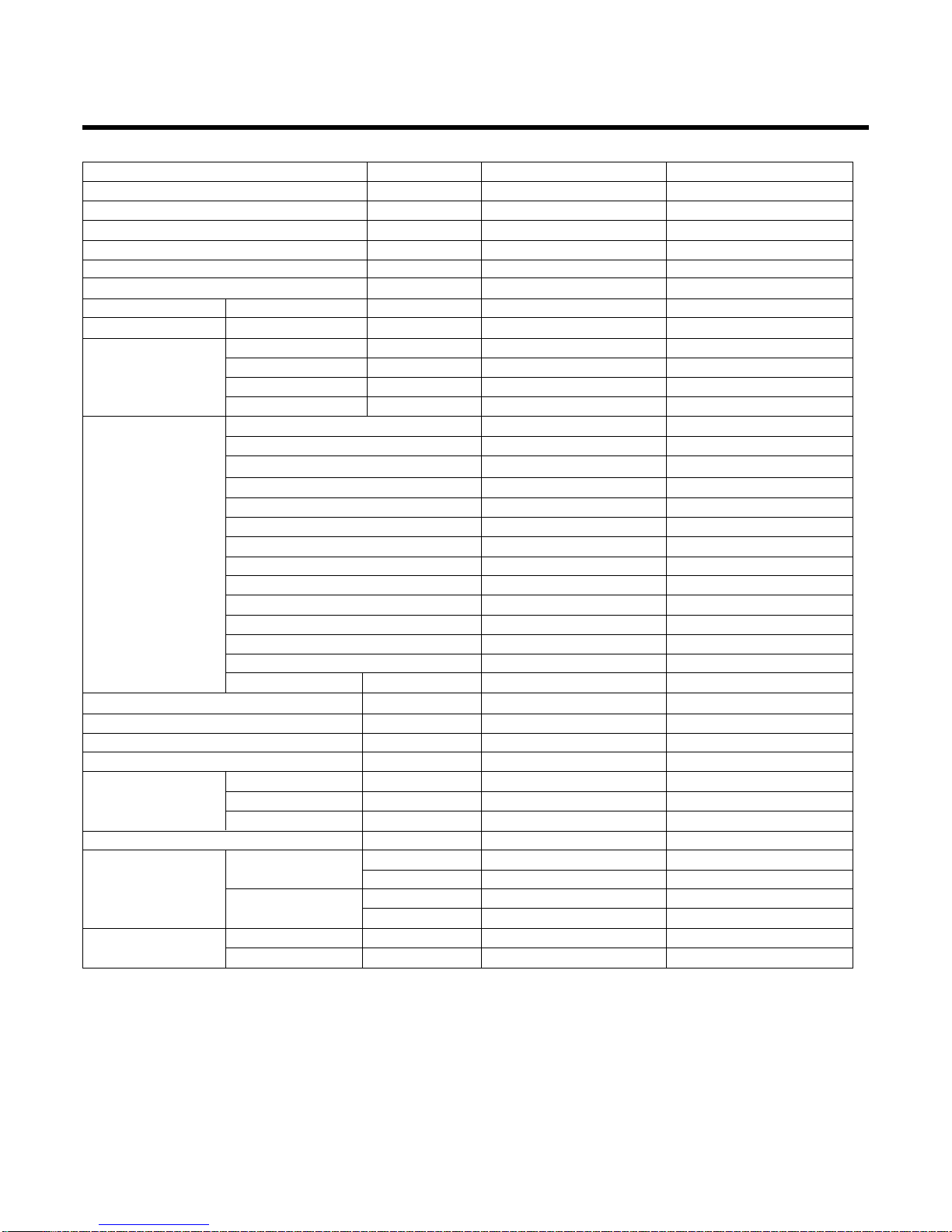
Items Unit
LSC091PMA LSC121PMA
Power Supply ø, V, Hz 1, 115V, 60 1, 115, 60
Cooling Capacity BTU/h 9,000 12,000
Input W 940 1,290
Running Current A 8.5 11.7
COMP. Locked Rotor AMP. A 46 58
E.E.R BTU/hW 9.6 9.3
Air Circulation m3/min(cfm) 7.1(250) 8.8(330)
Moisture Removal l/h(pts/hr) 1.2(2.6) 1.4(3)
Noise Level Indoor, High dB(A)±3 39 43
(Sound Med dB(A)±3 34 37
Pressure, 1m) Low dB(A)±3 30 34
Outdoor, Max dB(A)±3 46 46
Features Temperature Control Thermistor Thermistor
Air Deflection 4-way 4-way
Steps, Fan/Cool 3/4 3/4
Airflow Direction Control(up&down) Auto Auto
Airflow Direction Control(left&right) Manual Manual
Remocon Type Wireless LCD Wireless LCD
Setting Temperature Range, Cooling Mode 64~86°F 64~86°F
Temperature Increment 2°F 2°F
Auto Operation(electronic control) Yes Yes
Self Diagnosis Yes Yes
Timer 24hr, On/Off 24hr, On/Off
Sleep Operation Yes Yes
Healthy Dehumidification Mode Yes Yes
Restart Delay minutes 3 3
Refrigerant(R-22) Charge g(oz) 740(26.1) 630(22.2)
Power cord AWG #: P*mm214:3*2.5 14:3*2.5
Fuse or breaker Capacity A 15A 20A
Connecting Cable AWG #: P*mm216:4*0.75 18:4*0.75
Connecting Tube Liquid Side mm(in) 6.35(1/4) 6.35(1/4)
(ø. Socket Flare) Gas Side mm(in) 12.7(1/2) 12.7(1/2)
Length, std m(ft) 7.62(25) 7.62(25)
Additional Drain Hose(Outer Dia.) mm(in) 19(6/8) 19(6/8)
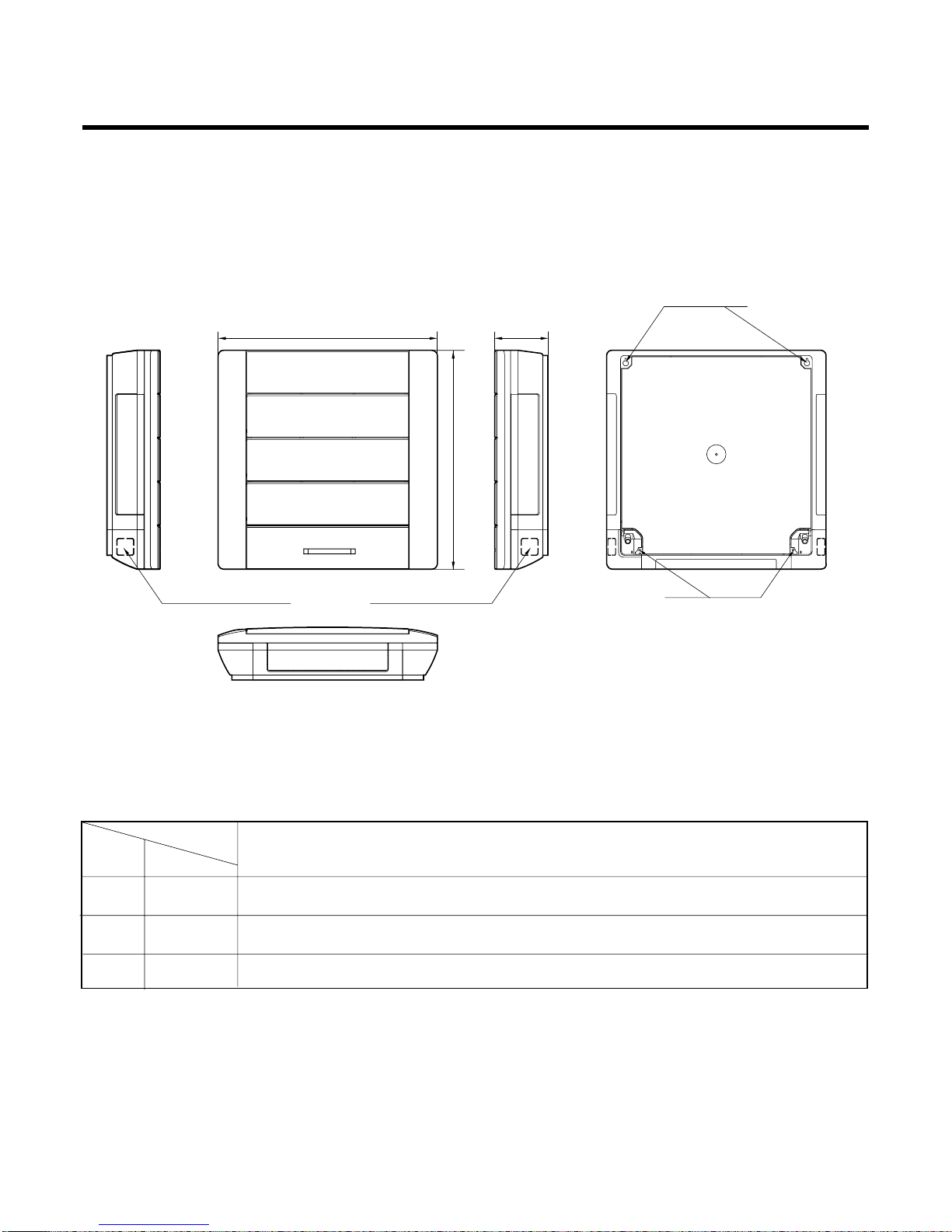
Dimensions Indoor mm 570*568*137 570*568*137
(WxHxD) in 22.4*22.3*5.4 22.4*22.3*5.4
Outdoor mm 770*540*245 770*540*245
in 30.3*21.3*9.6 30.3*21.3*9.6
Net Weight Indoor kg(lbs) 7(15.4) 7(15.4)
Outdoor kg(lbs) 33(72.8) 33(72.8)


 null")