Important Safety Instructions
2Dry contact for thermostat Installation manual 3
ENGLISH
Important Safety Instructions
3 IMPORTANT SAFETY INSTRUCTIONS
5 OVERVIEW
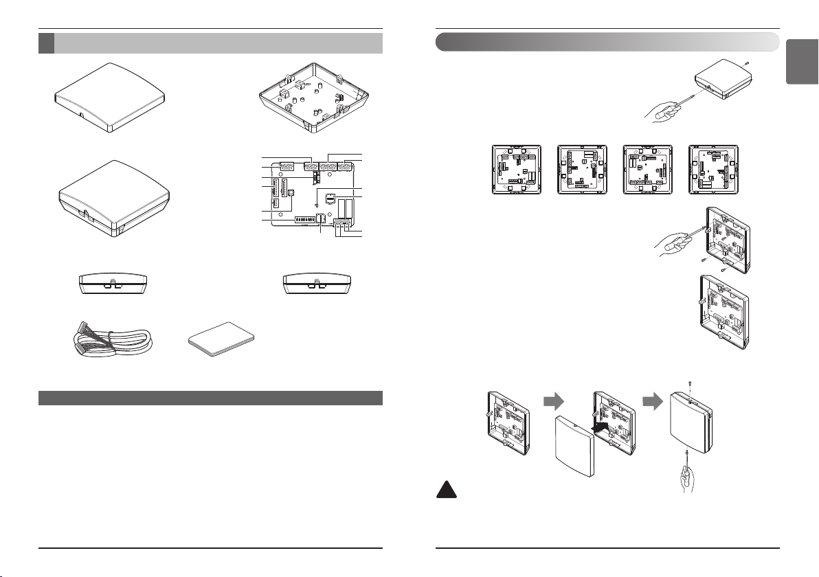
6 PART DESCRIPTON
7 Installation
8 SETTING AND USING METHOD
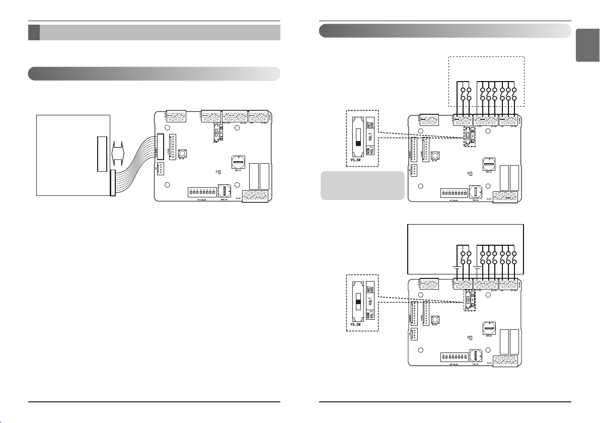
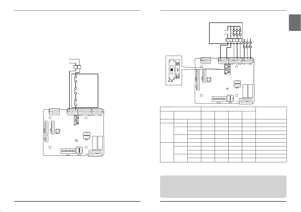
8 Power supply and indoor unit connection
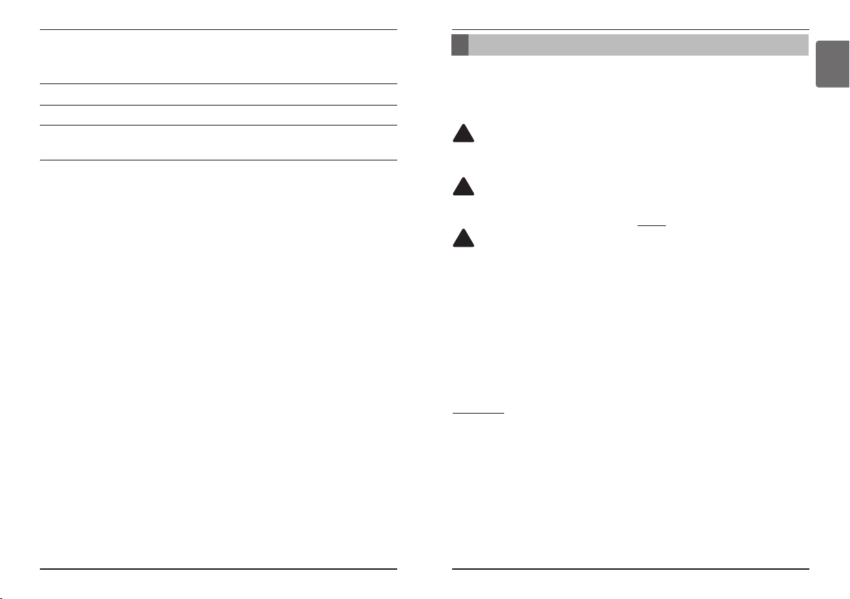
9 Setting of Contact Signal Input
10 Setting of ‘OPER_SW’
13 Setting of ‘TEMP_SW’
14 Set desired temperature using Universal Input
15 Installation of thermostat
21 Indoor unit monitoring
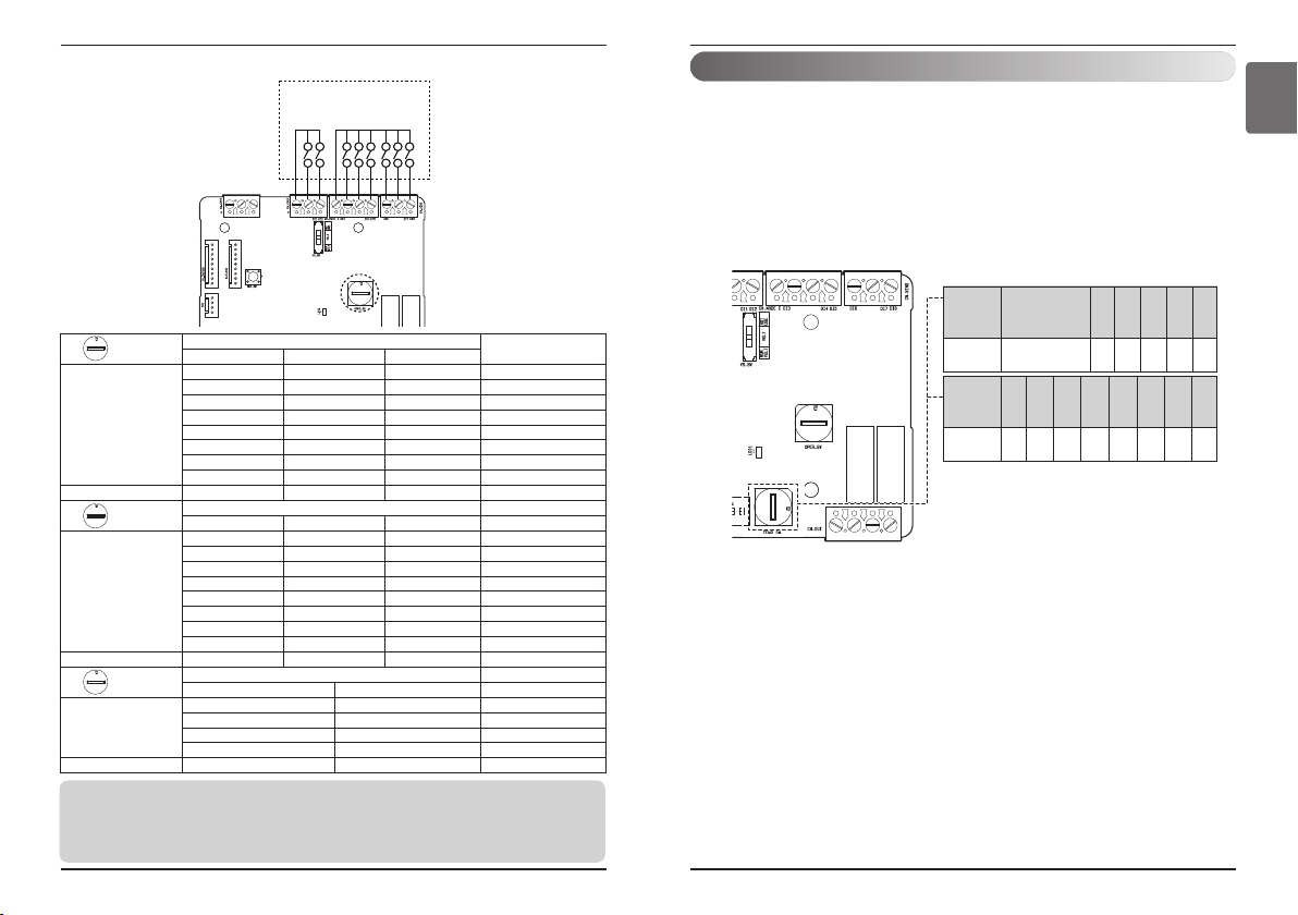
22 Function table for the input signal (For AWHP Indoor unit)
TABLE OF CONTENTS
READ ALL INSTRUCTIONS BEFORE USING
THE APPLIANCE.
Always comply with the following precautions to
avoid dangerous situations and ensure peak
performance of your product.
WARNING
It can result in serious injury or death when the
directions are ignored.
CAUTION
It can result in minor injury or product damage
when the directions are ignored.
WARNING
• Installation or repairs made by unqualified
persons can result in hazards to you and others.
• Installation work must be performed in
accordance with the National Electric Code by
qualified and authorized personnel only.
• The information contained in the manual is
intended for use by a qualified service
technician familiar with safety procedures and
equipped with the proper tools and test
instruments.
• Failure to carefully read and follow all
instructions in this manual can result in
equipment malfunction, property damage,
personal injury and/or death.
Installation
• Be sure to request to the service center or
installation specialty store when installing
products. It will cause fire or electric shock or
explosion or injury.
• Request to the service center or installation
specialty store when reinstalling the installed
product. It will cause fire or electric shock or
explosion or injury.
• Do not disassemble, fix, and modify products
randomly. It will cause fire or electric shock.
• Be sure to turn off power before installation. It
will cause electric shock.
• Installation work must be performed in
accordance with the national wiring standards
by authorized personnel only.
• Always perform grounding. Otherwise, it may
cause electrical shock.
• You need to use a safely insulated power
supply which follows IEC61558-2-6 anc NEC
Class2. If you do not follow, It may cause fire,
electric shock, explosion or injury.
• Securely attach the electrical part cover to
Module. If the electric part cover of Module is
not attached securely, it could result in a fire or
electric shock due to dust, water, etc.
• Make the connections securely so that the
outside force of the cable may not be applied to
the terminals. Inadequate connection and
fastening may generate heat and cause a fire.
In-use
• Do not place flammable stuffs close to the
product. It will cause fire.
• Do not allow water to run into the product. It will
cause electric shock or breakdown.
• Do not give the shock to the product. It will
cause breakdown when giving the shock to the
product.
• Request to the service center or installation
specialty store when the product becomes wet.
It will cause fire or electric shock.
• Do not give the shock using sharp and pointed
objects. It will cause breakdown by damaging
parts.
• Do not touch the board when the power is
connected. It can cause a fire, electric shock,
explosion, injury and problem to the product.
• Unplug the unit if strange sounds, smell, or
smoke comes from it. Otherwise, it may cause
electrical shock or a fire.
• The appliance must only be supplied at safety
extra low voltage corresponding to the marking
on the appliance.
• This appliance is not intended to be accessible
to the general public.
!
!
!
Table of contents