LG LWHD1807HR User manual

website http://www.I
Window-TypeAir
'S
MODELS, MODEL O'S: LWHD 2400HR', LINHD 1807HR
_s valuable
may
proper air
_pmper use.
order to p_vent
isuseor improper
for any damages
tioner.

FOR YOUR RECORDS
Write the model and serial numbers here:
Mode| #
_rial #
You can fir_ them _ a label on the side of each ua_.
Dea_eCs Name
Date Purchas_
II 8[ap[e you_ re_ip[ to [his page #_[t'_,ee_ant yc_ ne_ it
to prove date of purchase or for warranty issue.
READ THIS MANUAL
Inside _,u will find many h_p|ul hints o,n hc_v to use and
maintain _ur air cor_ditio,n_ pro_dy. Just a [i_le preventive
care on _3ur _[t _n _v_ y_ a great: deal ol time and
money over 'the life of your ai_ conditioner,
YouH find many an_w_s toi c,ommoa problems in the c_rt
of t_¢_b_ho_ing tips. if _u revi_ our ch_t d
Troubleshooting Tips first you may no_ _ to cal_ fo,r
serv_e at a&
• Contact: the, author{_d service t_hnician for repai_
or maintenance of this unit,
•Contact the install_ for installation ,of this unit.
•The air conditioner is not intendied for use by young
children o,r invalids without s,upervision.
• Yo_n_ chi|dten shoei_ be _rvis_ to e_s,ure that
they _o not play with the air conditioner:
• Whe_ tlhe power cord is to be repla_d, repla_ment
work shah be _rformed by aethorizedi personnel only'
_si#g o_ly g_uine r_lacement parts.
•|nstall_lon work musl be performed in _cor_a#ce
with the National Electric Code [by quailfi_ and
authorized personnel on|y,
2Room Air Conditioner

To prevent injjury i tOthe user or other people and property damage, the b_liowing instructions
must be fo!lowed,
[] Incorrect operation due to ignoring instruction will _use harm or damage. The seriousness
is cliassifi_ by the fol!oiwing indications,
I.......oz .s Ooss'O".o'deo'irso.'ou 'o.o1
[. CAUTION This symbo_indicates the possibility of injury or d_a_ to properties only.J
ii Meanings of symbols us,_ in this manual are as shown below,
Be sure. not to ,do,
Be sure to follow the instruction,
[] Installation
, O_herwise, it may _use a fire
or electrica_ sh_k,
•It may _use failure and
ellectnc shako
•Otherwi_, it may cause a fire
or eEectrica[Ishock,
°Sharp, _ges may cau_
injury.
• It will _u_ electric _k or fire
due _ heat genera_on,
• It may cau_ exp!osbn or fire,
Owner_ Manual 3

Il! Operation
•There ='sdanger of fire or electric
shocL
• _erwi_ it may cauce fire and
el_tric shock acc_ent.
• An oxygen shortage may occur,
•It willcause electric sh_ or fire
due to heat generation
•It willcause _aiiure of ma_ine or
ele_Eic sh_k_
° _henNi_, it m_y electrical
sho_ and failure.
° _herwise, it may _use a fire
or elect:rica_ sh_k,
• The ap_arance of the air
cond_ioner may deteriorate,
change color, or devebp surfa_
f_aws,_
° Since the fan rot_es at high
_,_d during operation, it may
cause iniury:
4 Room Air Conditioner
° Prevent accidenta! startup and
the,potability Ofiniury,

Safety Precautions
•Hwill cause e_ectricshock or fire °litwill cau_ elleclric shock or fire.. •It will _ui_ electric _ock.
due to heat generation_
• ff may cause etedric sh_ and
_mage •Othe_ise, it:m_y cau_
explosion, and a fire, • _ey are sharp and may cause
injury,
III In allatio, n
• O_erwi_, it may cause dispute w_h the
neigh_rs. •O_he_ise, it may cause vibration or water
[leakage.
Owner_ Manual 5

SafetyPrecautions
[] Operation
•it my cause injury. •, it m_ cause produ_ failure. •The appearance o1He air
conditioner m_ dietedorate,
change co.l.or,.ordevelop _rface
•It may _use an injury through
dropping of the unit or fa!lling
down.,
•' _tmay cause injury.
* Operation without fillers will
_use 'failure
•_herwise, it may do harm to
your hea_:h.
• it conlains con_inmer4s and will
make you sick.
* OthepMse, it may cau_
pe_onal injury.
6Room Air Conditioner

BeforeOperation
1. Contact an installation specialist for installation.
2. Plug in the power plug properly.
3. Use a dedicat_ circuit.
4. Do not use an extension cord.
5. Do not start/stop operation by plugging/unplugging the _wer cord.
6. If the _rd!plug is damage, replace it with only an authorized replacement
part.
iL!!Wii!ii!iiiiiiiiiiii'_'_
1i_ Being expos_ to direct airflow for an extend_ period of time could be
hazardous to your health. Do not expose _cupants, pets, or plants to direct
airflow for extended periods of time.
2i. Due to the _ssibilibt of oxygen deficiency, ventilate the r_m when used
together with stoves or other heating device&
3 Do not use this air conditioner for nonospecified special purples (e.g.
preserving precision devices, fo_, pets, plants, and art objects). Such u_ge
could damage the items.
1 Do not touch the metal _rts of the unit when removing the filter, Injuries can
occur when handling sharp metal edges.
2. Do not use water to clean inside the air oonditioner. Exposure to water can
destroy the insulation, leading to possible electric shock.
3i_When ,cleaning the unit, first make sure that the _wer and breaker are turn,_
off. The fan rotates at a very high speed during operation. There is a
_ssibiliby of injury if the unit's power is a_identally trigger_ on while
cleaning inner parts of the unit,
For repair and maintenance, contact your authorized service dealen
Owner_ Manual 7

Introduction
This symbol alerts you to the, risk of el_tric shock,.
This symbol alerts you to hazards that could cause harm to,
the air cond_ione, r.
This symbol indicates sp_ial notes.
This, appliance should _ installedin accordance _th the National Electric _de.
Air Filter
Eiec'_icH,eate
BasePan
Power Cord
Control Board
8 Room Air Conditioner

El_trical Safety
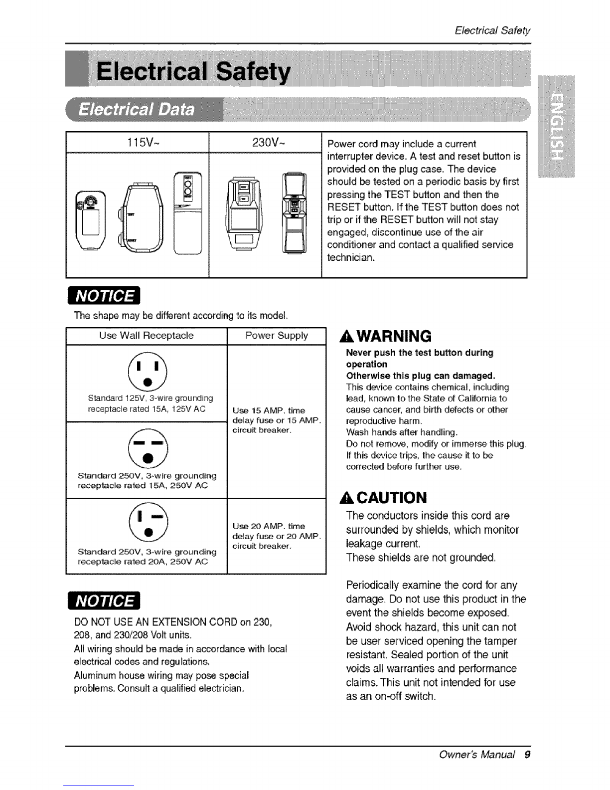
! 15V~ 230V- Power cord may include a current
inle,_upter device. A test and reset bu_on is
provided on the piug use. The device
should Ibete_ed on a periodic basis by first
pressing the TEST b_on and then the
RESET button, If the TEST button does not
tdp or if the RESET button will not stay
engage& discontinue use of the ,air
conditioner and contact a qualified service
technician.
The shape may be dif_rent according to its model.
U_ Wall Receptacle Power Supply
S'_Rdard 125V, 3owire grounding
receptacle rat_ 15A, i25V AC
S_ndard 250V, 3_wire grounding
r_ept_acl!e rated 15A, 2_:)V AC
SlPJn_rd 2_V, 3_wtre grounding
_ecep|ade rated _A, 250V AC
U_ 15 AMP, time
de_ay fu_ or !5 AMP,,
c#cu_t breaker°
U_, 20 AMP. time
de_ay fuse or :20, AMP,
circu_ breaker,
DO NOT USE AN EXq'ENSIO,NCORD on 2_,
_8, and 23_208 Vo_ un_s.
Alilwiring shouM be ma_ in accordance with local
electrical codes and regulations,
Aluminum house wiring may p_e sp_ia!
problem& _nsuff a qu,al#i_ eleddcian.
AWARNING
_vet push the test burton ,during
_herwise this plug can damage,
Th_ deJi_ c_ias chemical including
lead, kn_n to,the State d _li_omia to
cau_ car_er, and birth dd_Is or _h_
r_,roductive harm
Wash ha,ads aHer handfi_
Do not re,m_ve, modify _ immerse, th_ plug,
if th_ de_o4cetrips, the cau_ i_to be
corrected _fore further use.
CAUTION
The conductors inside this cord are
surrounded by shields, which moinitor
leakage current.
These shields a_e not ground_,
Periodically examine the co_d br any
damage, _ not u_ this p,mduct in the
event the shields become expos._.
Avoid sh_k hazard, this unit can not
user serviced opening the tamer
resistant. Sealed _rflon dthe unit
voids a!! warranties and! performance
claims, This unit not intended for use
as an on-off s"witch.
Ownerb Manual 9

(PLEASE READ CAREFULLY)
FOR THE USER'S PERSONAL SAFET_ THIS
APPLIANCE MUST BE PROPERLY GROUNOED
-[he' _#er cord _ _is appliance is equip_d with a
threo-pror_ (grounding) _ug. U_ thiis with a standard
th:_os|oi (grounding) wall _er out_et to minimize the
h_a_d of el[_tdc sh@ckoThe c_tomer shoul!d have the
wall receptac_ and circui! checked by a qualified
electrician to make sure the r_eptade is pro_dy
DO NOT CUT OR REMOVE THE THIRD (GROUND)
PRONG FROM THE P_ER PLUG,
A. SI_ATIONS WHEN'_E APPLIANCE WILL BE
DISCONNECTED OCCASIONALLY:
Because, _ IPot_tia_ safety hazards, we stronglly
discourage the use of an ada_ _ug_ H_ever, if you
wish to u_ an adapter, a TEMPORARY CONNECTION
may _ made. Use UL-iisted ada_er, availab_ from
most ]_al h_dvva_e stores.
....[he _arges]o_ in the adapter must b_ a]kjned w_h the
large slot in _he re_ptade to assure a _op_" _larity
conn,ect[®.
: Attachi_ _e adapter g_o,und terminall to _e walt
receptacle covet' screw do_ not ground the applian_
unless the cover sc_ is _1, and not Insu|a_ed, and
_e wa|i_r_ptacle is grounded through the house
wiring. The custom_ sho.u_ h_e the circuit choked
by a qualified electd_an to make sum _e receptacle
is properP] ground_,
Di_o=nn_t '|he _er _rd from the a_3,pter, using ,one
hand _ each. Otl_i_, the a_pte_ grou_ t_mir_]
m_ht break. DO NOT USE the ap_i_ce with a broken
adaple_ p_ugi.
_, SI'FUATI[ONS WHEN'THE APPLIANCE WILL BE
DISCONNECTED, OFTEN,i
C_ not use an ad@ter pi_ in thee, situations.
Unplugging the power oord frequently can lead to an
eventual breakage of the ground terminal The wan
power outlet should _ replaced by a |hr.-slot
(grounding) o_iet instead,
USE OF EXTENSION CORDS
Because d_t_tia_ _|ety hazards, we strongly
discourra,ge the use of an ext_sion cord. H_er, if
you wish to use an extension cord, _e. a CSA
certified_JL-[isted 3-v_re (grounding} extensbn cord
rated at i 5.A, 125V,
10 Ro,_m Air Coeditioner

Ins_llation
I/4 Bubbie
INSIDE
FOAM ...........
COOLED RADIATION
iL!!Wii!ii!iiiiiiiiiiii'_'_
1.To avoid vibration and noi_, make sure the unit is instaBed _curely and firmly.
2. In_alll the unit Sere the _nlight _es. not shine dir_lly on the unit.
If the unit re_iv_, direct sunlight, buBdan awning to,shade the cabinet,
3, _ere should be no ob_acle, like a fence, within 20'°which might re_rict heat radiation from the con_n_r,
4. To prevent reducing performance, instal[Ithe unit oo that louvers dthe cabinet are not blocked.
5, Install the unit a !_le obliquely outward not _ avoid leaking _e condensed water into the room (about 1/2"
or 1/4 bubble with level).
6. Installi_e unit wi_ its bottom potion _~60" ab,o_ the fl_r level.
7. Stuff the foam between the top dthe unit and the wall to prevent air and ins_ts from getting into the room.
8,.The power _rd mum be conneded to an inde_n_nt circuff. The green wire must be groiunded,
9, Connect the drain tube to the base pan hole in the rear si_ if you need to drain (consult a dealen),
Plastic hose or _uivallent may _ connected to the drain tu_.
The grilile is designed to.c_an the rifler both upward and downward.
(a) (b) (c)
A, Before a_aching the front grille toithe cabinet, ff _u want to pull o_ the filter upward;
1,.Open the inlet grille slightly (a).
2, Turn inside out the front griBe(a),
3. Disa_emble the tiniergrille from the fro,_ griBewith _parating the hinged part by in,fling a straight type
_rew.-dri_r tip (b).
4, Then, rolate the inlet gdil,e 180 degrees .andinsert the hooks into bottom holes of the front gdlle.
5. Inert _e filter and attach the front griBeto _e cabinet.
B, ff you want to p_i_ IO_ the filter downward;
The grili!,eis,already designed that way.
Owner_ Manual 11

Installation
All sup_rting pads should be _cured to,firm wood, masonry,
or metal
1. This unit is designed for instalation in standard doubi_ehung
windows with actual opening wi_hs from 2'9°'to 4!"
The top and bottom window sashes must open _fliciently to
all_ a ,clearvertical opening of 18" from the _ttom of the
upper _sh to the win_w st_L
2 TInestool off_t (height between the stool and sill),must be
le_ than 1 1/4.",
iF_ml strip Fc_m.,,PE
(Adhesive-Backed)
Type,C(5}
tTy_ O (2}
YCarnageBoll: (2') Lock Nut (4)
12 Ro,om, Air Co,nditioner

Ins_llation
S,CREWDR|VER(+,,-), RULER, KN|FE, HAMMER, PENCIL, LEVEL
PREPARATION OF CHASSIS
1. Remove the _rews which _asten the cabinet at
both _des ,andat the back_
2. Slide the unit out from the cabinet by gdppingl
the base pan handle and pulling_ard while
bracing the cabinet,
3. C_ the win_w sash _al to the proper length,,
Peel off the backing and ,attach the Foam°PE to
the un_r_de of the window sash.
Shipping screws
Fig. 1
4,.Remove the backing from _am-PE with 3,holes
and attach itto,the _ttom o_the Top retainer
bar,
5, Attach the,"Topretainer bar on the top of the
cabinet w_ 3 screws (T_,,peA)
6. In_rt the Frame guides into,the bottom of the
cabinet,
7. Inert the Frame Curtain into the Top retainer bar
and Frame guides.
8,,Fasten the,curtains to the,unit with 10 screws
(Type A) at _th sides.
Top relainer bar
Foam-PE
....Fop retainer bar
S_,_
(TypeA)
"Fr&me guide
Screw(Tyt_ A)
Owner_ Manual 13

Installation
1, Open the window: Mark a line o,nthe center of
the window stool be_een the _de window stop
moildin_.
L_sely attach the sill bracket to the support
bracket using the carriage bo_tand the lock nut:_
2. Attach the silll bracket to the window sill u_ng
thie_et, s (Type B)..
Carefulty p_acethe cabinet on the window stool
and align the _nter mark on the #attain front
with the center line marked window st_L
3 Using Me M-_rew and the I_k nut, attach the
support bracket to the cabinet track hole.Use,
the first track hob after the sBfbracket on Me
outer ewe of the window all. Tighten the
carriage bo._and the [_k nut..Be sure Me
cabinet slants ou_ard,
Do not drill a hole in the bottom pan, The unff is,
designed to operate with approximately 1/2" of
water in bottom pan,.
4, Purl Me bottom window sash down behind Me
Top re_iner bar until they"meet.
1. Do not pul! the window _sh down so flgN_,
that the movement o_ Frame curtain is
restricted. Attach the _binet _ the window
sloo.[ by driving the screws (Type B) through
the ,cabinet into window stool
2..The cabinet should I_ inslalled with a very
_ight tilt downward toward Me outside.
I Sill ' I
Bra Supped
. _.,/ [[_'----__IIIII Bracket
71H -- oo.o°,
(M-oScrew) [Ji'"
Cabinet_-,
Track hole
Machine_rew(Ty_ D}
bck nu_
sill
and bracket
Win_w _sh retainer bar
Frame cuRain
Foam PE
track
14 Ro,_m, Air Co#ditioner

Installation
5, PuBeach Frame curtain ruby _, each window _3sh
track, and pub the bosom window sash _wn behind
the Top retainer bar untff it meets,
6. Attach each Frame cudain the window _sh by
using screws,(Type C.) (See iFig.1O)
7, Sfide the unit into the cabinet (See Fig 1i)
CAUTION
Forsecudty pi_[_se, reinstall screws_ype A) at
_binet's si_s.
& C_ the Foam-strip to the pro_r [en@h.andinsert
betw_n the upper win_w sash and the lower
win,d{_w_s&(See Fig 12)
L,,iiiiiii'i'{iiii!iiiiiiiiiii'@iiiii/i
9_A_ach the Window locking bracket with a scr_
(Type C,) (See Fig, 13)
10. Attach _e front grili!,eto the _bine_ by in_r'ting '_e
ta_. on the gdiffeinto the tabs on the front of the
_binet. Pu@ the griffe in until it snaps into
place.(S_ Fig.14)
11. Lff_tthe inlet grille and secure it wffha screw (Type
A) through _e front grille.(See Fig. 14)
I2. Wind_ instaffation of room air conditioner is now
compbted, See ELECTRICAL DATAfor .attaching
_wer cord to ele_ricali outlet.
14
15
Owner_ Manual 15

OperatingInstructions
The remote control and con_ol panel will look like one of _e following picture&
1. POWER BUTTON
To _rn he air conditioner ON_pushthe b_on_ Toturn the air conditbner OFF,p_h the button again_
This button takes p.rior_, overany otherbutton.
2. OPERATION MODE SELECTION BUTTON
Everytime you push this bu_on, it wil_t_gle COOL, FAN and HEAT,
3, ON/OFFTiMER BU_ON
Ever_iime you push his Ibu_on,timer is se_as.bll_s..(1 Hour _ 2Hours _ 3Hours _ 4Ho.urs.-) 5Hours
-) 6Hours -)7Hours -) 8Hours _ 9Hou_ -) lOHours -)11Hours -) 12Hours -) CanceO
4. FAN SPEED SELECTOR
Eveqytimeyou [pushh_ _J_on, i{ _ set .asfo_!o_. (Hi[ Fe'] e Lowl 'F_ ] e Hi[ Fe ]'-_)
5, ROOM TEMPERATURE SETTING BUTTON
This button can automatically control the tem_rature _ the room The temperature can be set wffhin a
range of _°F to 86'_'F_ 1°E
6. AUTO SWING
This button can autoimatica_lycontrol the air fl!owdirec_on,
7. ENERGY SAVER
The _n stopswhen the _mpre_r stops cooling,,
A_,roximately eve_ 3munutesthe _n wilf turn ca and ch_k the roomair to _te_mine ifcooling is needed.
8, REMOCON SIGNAL RECEIVER
A slight heat odor may come from the uni'_when fir_ switching to HEAT after the cooling
season is over, This odor_ _used by fine drust particles on the heater, will disappear quickly.
[_d after an electrical power failure, the unit wifl begin to run at its last setting,
16 Ro,_m, Air Conditioner

Operatinginstructions
When the air ,conditioner has been _ffotmed i_ c_lin,g oper_ion and iisturn_ off or set to the fan
position,wait _least 3 minutes before resetting to tlhecoo_ingo_ration again,
1, Remove the _ver from the back of the remote
controller:
2, inert two batteries
* _ sure that the (+),and (o) directions are,
corre_.
._ sure that both batteri_, are new.
3, Re-a_ach the cover,
• I_ not u_ rechargeabUebatteri_,,
Such batteries, differ f:mm standard
dry ceils in shape, dimensions, and
performance,
• Remove the b,atter[esfrom the
remote controller if the aiir
_nditioner is not going to be u_d
for an extend_ lengtho__me,
Owner_ Manual 17

Operating Instructions
De ventilation _evermust be in the CLOSE posP_onin order to.maintain Me best cooling conditions,
When fresh air is necessary in the r_m, set the ventilation iever t,oMe OPEN _sition.
The damper is opened and room air is drawn oiuL
i _ ,Pa__
Before u_ng the ventilation feature,
pos_io.nthe le,ter, as shown. First, p,ull_wn
pa_ j_ t,ohorizon_l line with part ,:i_;;
De direction of air can be controlled wherever you
want to cool by adiusting the horizontal louver and the
vertical louver.
• MORIZO_AL AIR-DIRECTION COI',iTROL
To control horizontal direction of air flow, set to the,
ON position the air-swing swish and the air flow will
be swept horizon_llly by the automatic air-_ing
If you want _ stop Me air flow #om moving, _h off
the air swing switch at Me _sired position .of the
vahe,
VERTICAL AIR-DIRECTION COI'._ROL
The vertica! air dire_ion is adjusted by moving the
horizontal _ouver.
18 Ro,om, Air Co,nditioner

Operatinginstructions
_e air conditioner employs a proper drain melhod whereby the condensed water (moisture re_ved from the
air) is,drained to the ou_ide,
In very humid weather, (and for reverse cycle models in the reverse mo_) excessive, condensate water
removed from the, air may cause _me water to collect, To remove this excess,water you can install the drain
pan as detai_d _low.
1,Take Me drain pan which is bcated in the air di_harge
2. Remove the hole rubber from the base-pan (for some m_els),.
CABINET
3, Install the drain pan to the right corner of the cabinet with 4 (or 2)
_rews.
4. Conned the drain ho,_ of 315' insi_ diameter to the outlet l_ated
at the bottom of the drain pan You can purcha_ the drain hose or
tubing locally to satiny your particular needs. (Drain hose is not
supplied),.
DRAIN
PAN
DRAIN HOSE
A drain ho_ is.provided at the rear dthe air conditio,ner unit
Select a drain me_hodaccording to Me folilowing.
1, Remove the hole rubber kom the b,a_-pan (for _me models)
2, Conned a drain ho,_ of 9/t6 °'indde diameter to Me @ain pipe,as
_own in Fig. 1..
3. Or conned a pipe elbow d9/16" insid_ diameter to the drain pipe,
then conned .adrain ho_ of 9/16" inside diameter to the pi_
elbow as shown in Fig.,2, DRAIN HOSE
Owner_ Manual 19

MaintenanceandService
TURN THE AIR CONDITIONER OFF AND REMOVE THE PLUG FROM THE POWER OUTLET.
he air filltershould be choked! at least Mice a menh toi see if cleaning is n_es_ry,, Trapped particles in the
filter will build up and block the airflow, This reduces the _oling _paci_ and also cauls an accumulation of
ffo,_ on the c_ling coils.
1,,Open the inlet grille upward by pulling out the bottom of the inlet grille.(a)
In another c,ase_you _n open the inUet,gri_edownward by pulling out the top of the inlet grill!e,(b)
2,.Remove,the air filter #om the, front grille assembly by pulling the air filter upior down slightly.
3, Wash he filter using lukewarm wmer below 40°C (10,4°F),(c)
4, Gent_'yshake the exce_ water kom the filter comp_tely. RelPla_ the filter,
(a) (b) (c)
Mark i_ o_inlet grille means opening diredion_
1,,Pull down front gdile from he cabinet top.
2 Push front grille's,tips,toward the cabinet in ordor
toi inert 'front grilWs ta_, into
_hecabinet,,
3. O_n the inlet grille.
4 Tighten the screw through the kont grille into the
plate ot the evaporator or baH, pan.
5,,Close inlet gri_{e,
20 Ro,_m, Air Conditioner
This manual suits for next models
1
Table of contents
Languages:
Other LG Air Conditioner manuals
Popular Air Conditioner manuals by other brands

DURASTAR
DURASTAR DRAL12F1A installation manual

Beper
Beper Mammut VE550 use instructions

Carrier
Carrier 50ZP Series owner's manual

Beko
Beko 10M-8899243200-4921-01 user manual

Innova
Innova 2.0 Instructions for installation, use and maintenance manual

Carrier
Carrier 50MH Installation, Start-Up and Service Instructions