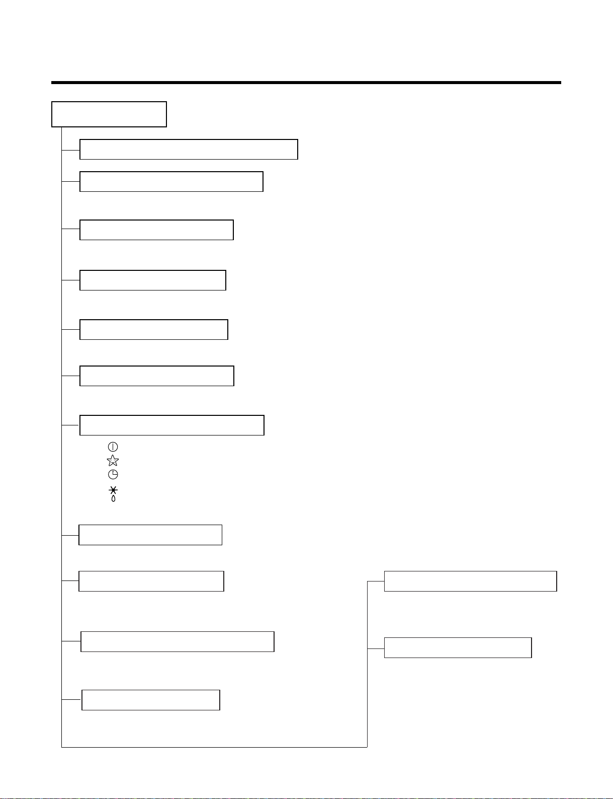
LG LS-J0761CL User manual

SERVICE MANUAL
Room Air Conditioner
MODEL : LS-J0761CL / CM / CN / CD / CS
LS-J0761HL / HM / HN / HD / HS
LS-J0962CL / CM / CN / CD / CS
LS-J0962HL / HM / HN / HD / HS
LS-J0963CL / CM / CN / CD / CS
LS-J0821CL / CM / CN / CD / CS

Contents
Functions.................................................................................................................................3
Product Specifications (Cooling Only)..................................................................................5
Product Specification (Cooling & Heating)...........................................................................6
Dimensions..............................................................................................................................7
Refrigeration Cycle Diagram................................................................................................10
Wiring Diagram......................................................................................................................11
Operation Details ..................................................................................................................13
Display Function ...................................................................................................................20
Self-diagnosis Function........................................................................................................20
Installation .............................................................................................................................21
Operation ...............................................................................................................................37
Disassembly of the parts (Indoor Unit)...............................................................................39
2-way, 3-way Valve.................................................................................................................42
Cycle Troubleshooting Guide...............................................................................................49
Electronic Parts Troubleshooting Guide.............................................................................50
Electronic Control Device.....................................................................................................57
Schematic Diagram...............................................................................................................59
Exploded View & Replacement Parts List...........................................................................61
-2-

Functions
• Room temperature sensor. (THERMISTOR)
• Maintains the room temperature in accordance with the Setting Temp.
• Indoor fan is delayed for 5 sec at the starting.
• Restarting is inhibited for approx. 3 minutes.
• High, Med, Low, CHAOS
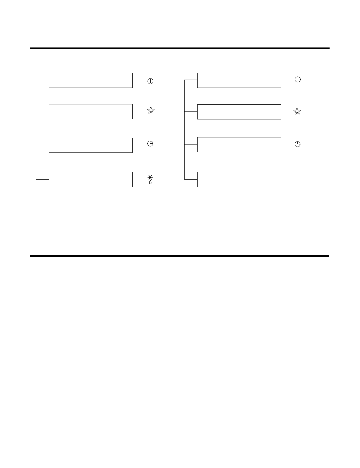
--- Lights up in operation
--- Lights up in Sleep Mode
--- Lights up in Timer Mode
--- Lights up in Defrost Mode (for Heating Model)
OUTDOOR --- Lights up in compressor operation (for Cooling Model)
• Intermittent operation of fan at low speed.
• The fan is switched to low(Cooling), med(Heating) speed.
• The unit will be stopped after 1, 2, 3, 4, 5, 6, 7 hours.
• The fan is switched to intermittent or irregular operation
•
The fan speed is automatically switched from high to low speed.
• The louver can be set at the desired position or swing
up and down automatically.
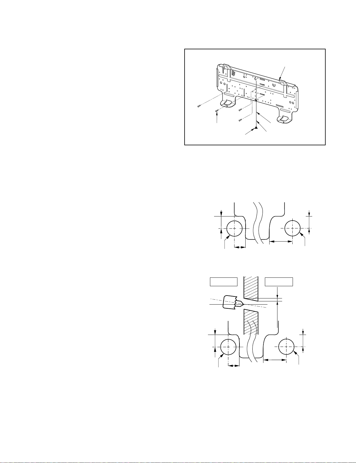
Indoor Unit
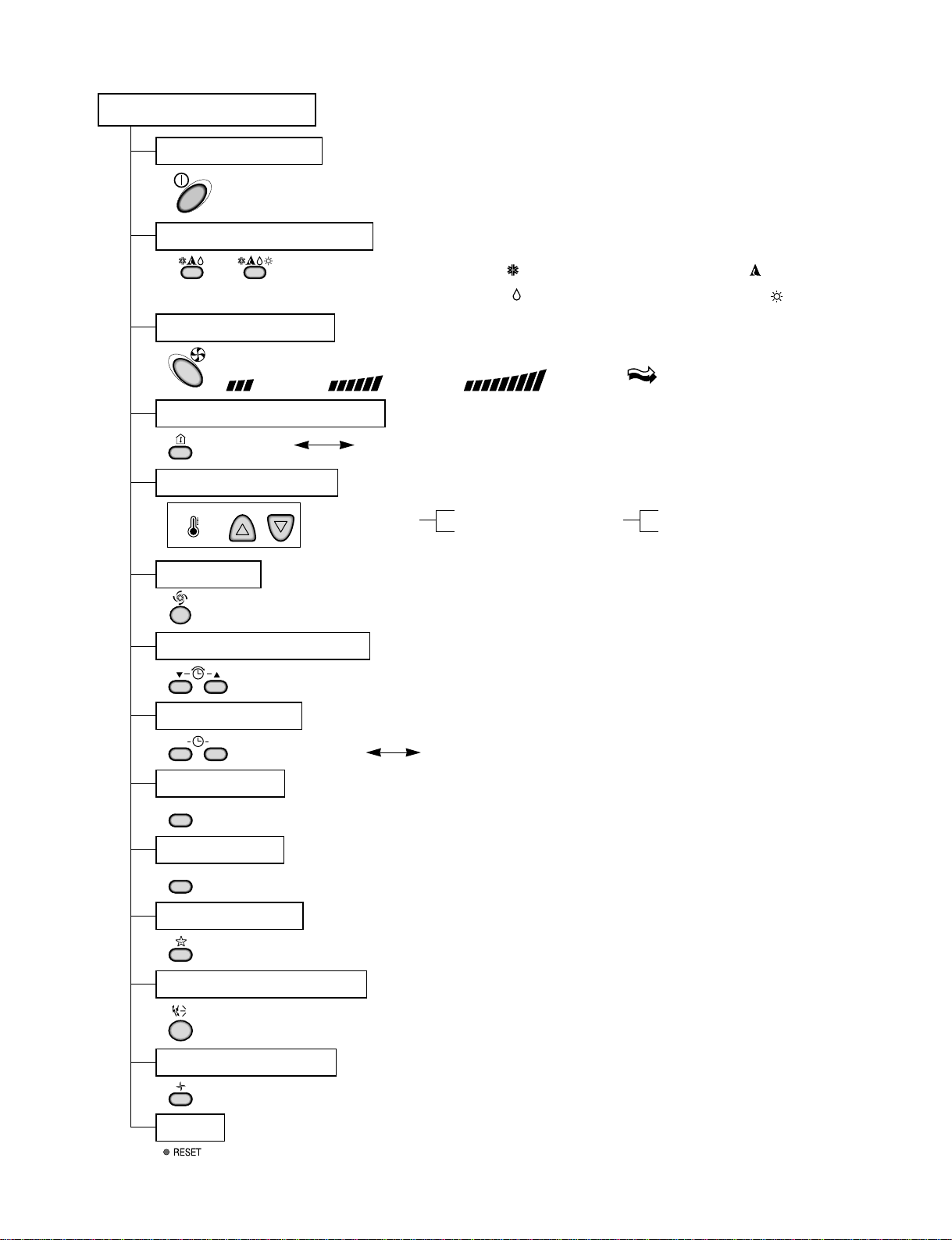
Operation ON/OFF by Remote controller
Sensing the Room Temperature
Room temperature control
Starting Current Control
Time Delay Safety Control
Indoor Fan Speed Control
Operation indication Lamps (LED)
Soft Dry Operation Mode
ƒU Both the indoor and outdoor fan
stops during defrosting.
ƒU The indoor fan stops until the
evaporator pipe temperature will be
reached at 28°C.
Sleep Mode Auto Control
Natural Air Control by CHAOS Logic
Airflow Direction Control
-3-
Defrost(Deice) control (Heating)
Hot-start Control (Heating)

-4-
Soft Dry Operation Mode.( )
Remote Controller
Operation ON/OFF
Reset
Operation Mode Selection
Temperature Setting
Timer Selection
Timer Setting
JET COOL
Timer Cancel
Sleep Operation
Airflow Direction Control
(Cooling
model only) (Heating
model only)
TEMPERATURE LOWHIGH
Cooling Operation Mode.( ) Heating Operation Mode.( )
Auto Operation Mode.( )
Fan Operation Mode
Room, Temperature Display
Setting the Time or Timer
ON OFF
SET
CANCEL
Fan Speed Selection
(Low) (Med) (High) (CHAOS)
: (High: 39°C LOW : 11°C)
Down to 18°C
Up to 30°C
Cooling
: OFF, ON, OFF ON
: Cancel Sleep Mode, Timer ON or Timer OFF
: 1, 2, 3, 4, 5, 6, 7, Off Timer
: Fan Operates without cooling or heating.
Down to 16°C
Up to 30°C
Heating

Display Function
1. Heating Model 2. Cooling Model
• Cooling, Soft Dry, Fan, Heating • Cooling, Soft Dry, Fan
• Sleep Mode • Sleep Mode
• Timer Mode • Timer Mode
• Hot-start, Defrost
Self-diagnosis Function
■Thermistor Error Indicator
• When the indoor pipe sensor or the room temperature sensor is open or is shorted, the error is indicated.
• To indicate the error, the operation LED (or the cooling LED) flashed at 3 sec interval.
• When the error is cleared, the LED stops flashing, the operation (or cooling) LED is on.
• While in appliance pause, the error is not indicated.
Operation Indicator
Timer Indicator
Sleep Timer Indicator
Defrost Indicator
-20-
Operation Indicator
Timer Indicator
Sleep Timer Indicator
Compressor on Indicator OUT
DOOR

Installation
1. Installation of indoor, Outdoor unit
-21-
More than 2.3 m
More than 5 cm
More than
5 cm More than
5 cm
More than 10 cm More than 10 cm
More than 70 cm
1) Selection of the best location
1. Indoor unit
2. Outdoor unit
• There should not be any heat source or steam
near the unit.
• There should not be any obstacles to prevent the
air circulation.
• A place where air circulation in the room will be
good.
• A place where drainage can be easily obtained.
• A place where noise prevention is taken into con-
sideration.
• Do not install the unit near the door way.
• Ensure the spaces indicated by arrows from the
wall, ceiling, fence or other obstacles.
• If an awning is built over the unit to prevent
direct sunlight or rain exposure, be careful
that heat radiation from the condenser is not
restricted.
• There should not be any animals or plants
which could be affected by hot air dis-
charged.
• Ensure the correct distance is left from the
wall, ceiling, fence, or other obstacles as indi-
cated in the diagram.
Install the indoor unit on the wall where the height
from the floor is more than 2.3 meters.
CAUTION

-22-
5-7mm
Indoor Outdoor
WALL
Right rear piping
Installation plate
Marking-off line
Thread
Weight
Type "A" screw
Left rear piping
ø70mm
ø70mm
80mm
50mm
40mm
40mm
ø70mm
ø70mm
80mm
50mm
40mm
40mm
2) Indoor Unit Installation
The mounting wall should be strong and solid enough
to protect it from the vibration.
1.Mount the installation plate on the wall with four
Type "A" screws.
(if mounting the unit on the concrete wall, consider
using anchor bolts.)
• Always mount the Installation plate horizontally by
aligning the marking-off line by means of the
thread and a level.
2. Drill the piping hole with 70mm dia. holecore
drill.
• Line according to the arrows marked on lower the
left and the right side of the Installation Plate.
The meeting point of the extended line is the cen-
ter of the hole.
• Drill the Piping hole at either the right or the left
and the hole should be slightly slanted to the out-
door side.
The lower left and right side of Installation
Plate

-23-
2. Piping and Drainage of Indoor Unit
1) Preparation of Piping
1. Cut the pipes and the cable.
• Use the accessory piping kit or the pipes pur-
chased locally.
• Measure the distance between the indoor and the
outdoor unit.
• Cut the pipes a little longer than measured dis-
tance.
• Cut the cable 1.5m longer than the length of the
pipe.
2. Remove burrs.
• Remove burrs from cut edges of pipes.
• Turn the pipe end toward down to avoid the metal
powder entering the pipe.
Caution:
If burrs are not removed, they may cause a gas leak-
age.
3. Flaring the pipes.
• Insert the flare nuts, mounted on the connection
ports of both indoor and outdoor unit, onto the
copper pipes. (When the flare nuts are removed
from the indoor unit.) Some gas may leak, as
some gas is charged to prevent the inside of the
pipe from rusting.
• Fit the copper pipe end into the Bar of flare tool
about 0~1.0mm higher.
(See illustration)
• Flare the pipe ends.
4. Tape the flaring portion to protect it from the
dust or damages.
90 Slanted Rough
Pipe cutter
Pipe
Reamer
Point down
"A"
Bar
Bar
Clamp handle Red arrow mark
Cone
Yoke
Handle
Copper pipe
Inclined Cracked Uneven
thickness
Surface
damaged
= Improper flaring =
When properly flared, the internal surface of the flare will
evenly shine and be of even thickness.
After the flare part comes into contact with the connec-
tors, carefully check the flare finish.
"A"; ø15.88 mm (5/8") ¡0~1.0 mm
ø12.7 mm (1/2") ¡0~0.5 mm
ø9.52 mm (3/8") ¡0~0.5 mm
ø6.35 mm (1/4") ¡0~0.5 mm

-24-
Installation plate
Pull
Pull
Drain hose
Indoor Outdoor
Connecting cable
Connecting
piping
Drain pipe
Indoor unit tubing Flare nut
Spanner Torque wrench
Plastic bands
Drain hose
Adhesive
Drain pipe
Insulation material
Pipings
2)
Connection of Pipings
1. Remove the installation plate
• Pull the two '∆' marked portion of bottom of the
chassis and pull the installation plate out of chas-
sis.
2. Route the drain hose and the indoor tubing.
For right rear piping
3. Insert the piping, the connecting cables and the
drain pipe through the piping hole on the wall.
4. Connect the piping and the indoor tubing, and
drain hose and drain pipe.
• Don't connect the cable to the indoor unit.
• Wrap the insulation material around the connect-
ing portion.
• Glue up the connection portion of drain hose and
drain pipe.
Pipe Size Torque
Liquid Side (1/4") 1.8kg.m
Gas Side (3/8") 4.2kg.m
Gas Side (1/2") 5.5kg.m

-25-
Taping
Conecting
cable Gas side
piping
Drain hose Liquid side
piping
Connecting
cable
Drain hose
Press the lower left and right side of the unit against
the Installation Plate until the hooks engage with their
slots (sound click).
5. Bend the tubing as shown in the figure and bind
the piping, the connecting cables and the drain
hose altogether.
• Make a small loop for easy connection later.
6. Wrap the tubing, the drain hose and the con-
necting cable with tape.
7. Indoor unit installation
• Hook the indoor unit onto the upper portion of the
installation plate. (Engage the two hooks of the
rear top of the indoor unit with the upper edge of
the installation plate.)
Ensure the hooks are properly seated on the
installation plate by moving it in left and right.
CAUTION
Take care to arrange the piping, drain hose and
cables as the feature 7 page for inserting it into the
indoor unit and mount the indoor unit on the instal-
lation plate.
CAUTION
When install, make sure that the remaining parts
must be removed clearly so as not to damage the
piping and drain hose, especially power cord and
connecting cable.

-26-
Indoor unit tubing Flare nut
Spanner Torque wrench
Plastic bands
Drain hose
Adhesive
Drain pipe
Insulation material
Pipings
Taping
,
Indoor Outdoor
Connecting cable
Connecting
piping
Drain pipe
Drain hose
Drain hose
Installation plate
Pull
Pull
For left rear piping
3. Insert the connecting cables, the drain pipe and
connecting piping through the piping hole on
the wall.
4. Connect the piping and the indoor tubing, and
drain hose and drain pipe and place the drain
pipe into the chassis.
• Don't connect the cable to the indoor unit.
• Make a small loop for easy connection later.
• Glue up the connection portion of drain hose and
drain pipe.
5. Bend the drain hose and bind the drain hose,
the piping and the connecting cables altogether.
Pipe Size Torque
Liquid Side (1/4") 1.8kg.m
Gas Side (3/8") 4.2kg.m
Gas Side (1/2") 5.5kg.m

-27-
Connecting
cable
Drain hose
Indoor/outdoor
connecting cable
Connecting
cable
Taping
Gas side piping
Liquid side piping
Drain hose
Press the lower left and right side of the unit against the
Installation Plate until the hooks engage with their slots
(sound click).
6. Wrap the insulation material around the connect-
ing portion.
7. Wrap the tubing, the drain hose and the connect-
ing cable with tape.
8. Indoor unit installation
• Hook the indoor unit onto the upper portion of
installation plate. (Engage the two hooks of the
rear top of the indoor unit with the upper edge of
the installation plate.)
Ensure the hooks are properly seated on the
installation plate by moving it left and right.
CAUTION
Take care to arrange the piping, drain hose and
cables as the figure 7 page for inserting it into the
indoor unit and mount the indoor unit on the installa-
tion plate.

-28-
Outdoor unit
Liquid side piping
(Smaller Dia.)
Torque wrench
Gas side piping
(Bigger Dia.)
1) Connecting the piping to the Outdoor
unit
1. Align the center of the piping and sufficiently
tighten the flare nut with fingers.
2. Finally, tighten the flare nut with torque wrench
until the wrench clicks.
• When tightening the flare nut with torque wrench,
ensure the direction for tightening follows the arrow
on the wrench.
CAUTION
After the confirmation of the above conditions, prepare the wiring as follows:
1) Never fail to have an individual power specialized for the air conditioner. As for the method of wiring,
be guided by the circuit diagram pasted on the inside of control box cover.
2) Provide a circuit breaker switch between power source and the unit.
3) The screw which fasten the wiring in the casing of electrical fittings are liable to come loose from
vibrations to which the unit is subjected during the course of transportation. Check them and make
sure that they are all tightly fastened. (If they are loose, it could give rise to burn-out of the wires.)
4) Specification of power source.
5) Confirm that electrical capacity is sufficient.
6) See to it that the starting voltage is maintained at more than 90 percent of the rated voltage marked
on the name plate.
7) Confirm that the cable thickness is as specified in the power sources specification.
(Particularly note the relation between cable length and thickness.)
8) Never fail to equip a leakage breaker where it is wet or moist.
9) The following troubles would be caused by voltage drop-down.
• Vibration of a magnetic switch, damage on the contact point there of, fuse breaking, disturbance to the nor-
mal function of a overload protection device.
• Proper starting power is not given to the compressor.
3. Connecting Piping and Cable to the outdoor unit
Pipe Size Torque
Liquid Side (1/4") 1.8kg.m
Gas Side (3/8") 4.2kg.m
Gas Side (1/2") 5.5kg.m

Connecting
cable
Terminal block
(Pillar terminal)
Cover control
Outdoor unit
Over
5mm Holder for
connecting
cable
Over 5mm
Terminal block
(Pillar terminal)
Holder for
power supply
cord
Cover control
Connecting cable
-29-
2)
Connection of the cable
1. Remove the cover control from the unit by loosen-
ing the screw.
Connect the wires to the terminals on the control
board individually as the following.
Outdoor unit
2. Secure the cable onto the control board with the holder
(clamper).
3. Refix the cover control to the original position with the
screw.
4. Use a recognized circuit breaker 16A between the power
source and the unit. A disconnection device to adequately
disconnect all supply lines must be fitted.
1(L)Terminals on the outdoor unit
Terminals on the outdoor unit
Terminals on the indoor unit
1(L)
1(L)
1(L)
2(N)
2(N)
2(N)
3 4
34
2(N)
BROWN BLUE G/Y BLACK RED
BROWN BLUE G/Y RED
BROWN
BROWN BLUE BLACK
BLACK
G/Y RED
REDG/Y
BLUE
BROWN
BLUE
GREEN/YELLOW
BROWN BLUE
GREEN/YELLOW
1) Cooling only type
2) Cooling & Heating type
The power cord connected to the indoor unit should
be complied with the following specifications (Type
H05VV-F approved by HAR or SA).
The connecting cable connected to the indoor and
outdoor unit should be complied with the following
specifications (Rubber insulation, type H07RN-F
approved by HAR or SA).
NORMAL CROSS-
SECTIONAL AREA
1.0mm2
NORMAL CROSS-
SECTIONAL AREA
1.0mm2
Color of Wires
Color of Wires
The length of the power supply cord should be over 1.8m measured from the power supply cord entry of the cabinet to the
middle of the live pin of the plug.
Color of Wires
Color of Wires
LS-J0761HL/CL
LS-J0821CL
LS-J0962CL
LS-J0962HL

-30-
Pull the right and
the left side.
Screw
1) Checking the Drainage
1. Remove the Grille from the cabinet.
• Set the up-and-down air direction louver to the
open position (horizontally) by finger pressure.
• Remove the securing screws.
• To remove the Grille, pull lower the left and right
side of the grille toward you (slightly tilted) and lift
it straight upward (Two tabs on the top inside edge
of chassis are clear of their slots).
2. Check the drainage.
• Pour a glass of water on the evaporator.
• Ensure if water flows drain hose of indoor unit
without any leakage.
4. Checking the Drainage and Connecting the cable to Indoor unit

-31-
Connecting cable
2) Connecting of the cable to the indoor
unit
1. Connect the wires to the terminals on the con-
trol board individually according to the out-
door unit connection.
• Ensure that the color of the wires of outdoor
unit and the terminal No. are the same as the
indoor unit.
2. Attach the Grille onto the cabinet.
• Grasp lower the left and the right side of the
Grille and engage two tabs on the top inside
edge of the grille with two slots on the cabinet's
top front edge.
• Press the Grille toward to the cabinet until it will
be back into place.
1(L)Terminals on the outdoor unit
Terminals on the outdoor unit
Terminals on the indoor unit
1(L)
1(L)
1(L)
2(N)
2(N)
2(N)
3 4
34
2(N)
BROWN BLUE G/Y BLACK RED
BROWN BLUE G/Y RED
BROWN
BROWN BLUE BLACK
BLACK
G/Y RED
REDG/Y
BLUE
BROWN
BLUE
GREEN/YELLOW
BROWN BLUE
GREEN/YELLOW
1) Cooling only type
2) Cooling & Heating type
Color of Wires
Color of Wires
Color of Wires
Color of Wires

-32-
Plastic band
Taping
Drain hose
Pipings
Connecting
cable
• Trap is required to prevent the electrical
parts from entering the water.
Trap
Seal a small opening
around the pipings
with gum type sealer.
3) Form the piping
1. Wrap the connecting portion of indoor unit with
the Insulation material and secure it with two
Plastic Bands.(for the right piping)
• If you want to connect an additional drain hose,
the end of the drain-outlet should be off the
ground.(Do not dip it into water, and fix it on the
wall to avoid swinging in the wind.)
2. Tape the Piping, drain hose and Connecting
Cable from down to up.
3. Form the piping gathered by taping along the
exterior wall and fix it onto the wall by saddle or
equivalent.
2. Tape the Pipings and Connecting cable from
down to up.
3. Form the pipings gathered by taping along the
exterior wall, make the Trap to be required to
prevent the room from entering the water.
4. Fix the pipings onto the wall by saddle or equiv-
alent.
In case of the Outdoor unit to be installed
below the position of the Indoor unit.
In case of the Outdoor unit being installed
upper position of the Indoor unit.

-33-
Gas side
Liquid side
Cap
Hexagonal
wrench
2-way valve
(Open)
3-way valve
(Close)
No leakage found Leakage found
• Re-tighten the connecting portion with torque
wrenches.
Leakage ceased Leakage persists
Leakage ceased
Repair
Result
5. To open 2-way valve again, turn the valve
stem counter-clockwise until it stops.
Terminal block
(pillar terminal)
6. To purge the air, push the pin on the service port of 3-
way valve for three seconds with a hexagonal wrench
and set it free for one minute.
7. Set both liquid and gas side valves to open
position with the Hexagonal wrench for the
unit operation.
5. Air Purging of the Piping and Indoor Unit
1) Air purging
The air remaining which contains moisture in the
refrigeration cycle may cause a malfunction on the
compressor.
1. Remove the caps from the 2-way and 3-way
valves.
2. Remove the service-port cap from the 3-way
valve.
3. To open the valve, turn the valve stem of 2-way
valve counter-clockwise approx. 90¡˘and hold it
there for five seconds, then close it.
4. Check a gas-leakage of the connecting portion of
the pipings.
CAUTION: Do not leak the gas in the air during
air purging, with vacuum pump as
possible as you can.

-34-
8. Checking a gas leakage
(1) Connect the manifold gauge to the service port of 3-way valve.
Measure the pressure.
(2) Keep it for 5-10 minutes.
Ensure if the pressure indicated on the gauge is as same as that of measured at first time.
Liquid side
Gas side
CLOSE
CLOSE
Indoor unit Outdoor unit
Closed
Closed
NOTE:
The additional gas for air purping has been charged in the outdoor unit.
However, if the flare connections have not been done correctly and there gas leaks, a gas cylinder and the charge
set will be needed.
CAUTION : Do not leak the gas in the air during air purging. Use vaccum pump as far as possible

-35-
A
A
B
Oil trap
Outdoor unit
Indoor unit
Outdoor unit
Indoor unit
B
6. Pipe length and the elevation
• Capicity is based on standard length and maximum allowance length is the basis of reliability.
•Oil trap should be installed per 5~7 meters.
• Numerical value in "( )" is for Rotary Comp. model.
CAUTION
In case more than 5m
Max. Piping
Length
£(m)
Capacity
(Btu/h)
7~12K 15 7 5 20
Max.
Elevation
£(m)
Standard
Length(m) Additional Refrig-
erant
(g/m)
This manual suits for next models
29
Table of contents
Other LG Air Conditioner manuals
Popular Air Conditioner manuals by other brands

Hisense
Hisense 7K Use and Installation Instructions

GE
GE AHE18 Series Owner's manual and installation instructions

York
York PCG4 Series installation manual

TECHWOOD
TECHWOOD TRF-7008 instruction manual

Technibel
Technibel MCAV77C5VAB Technical data & service manual

Daikin
Daikin RXYQ72PAYD installation manual