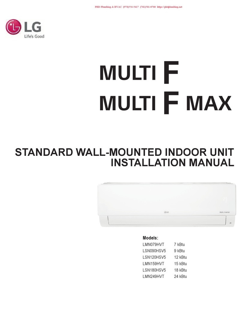
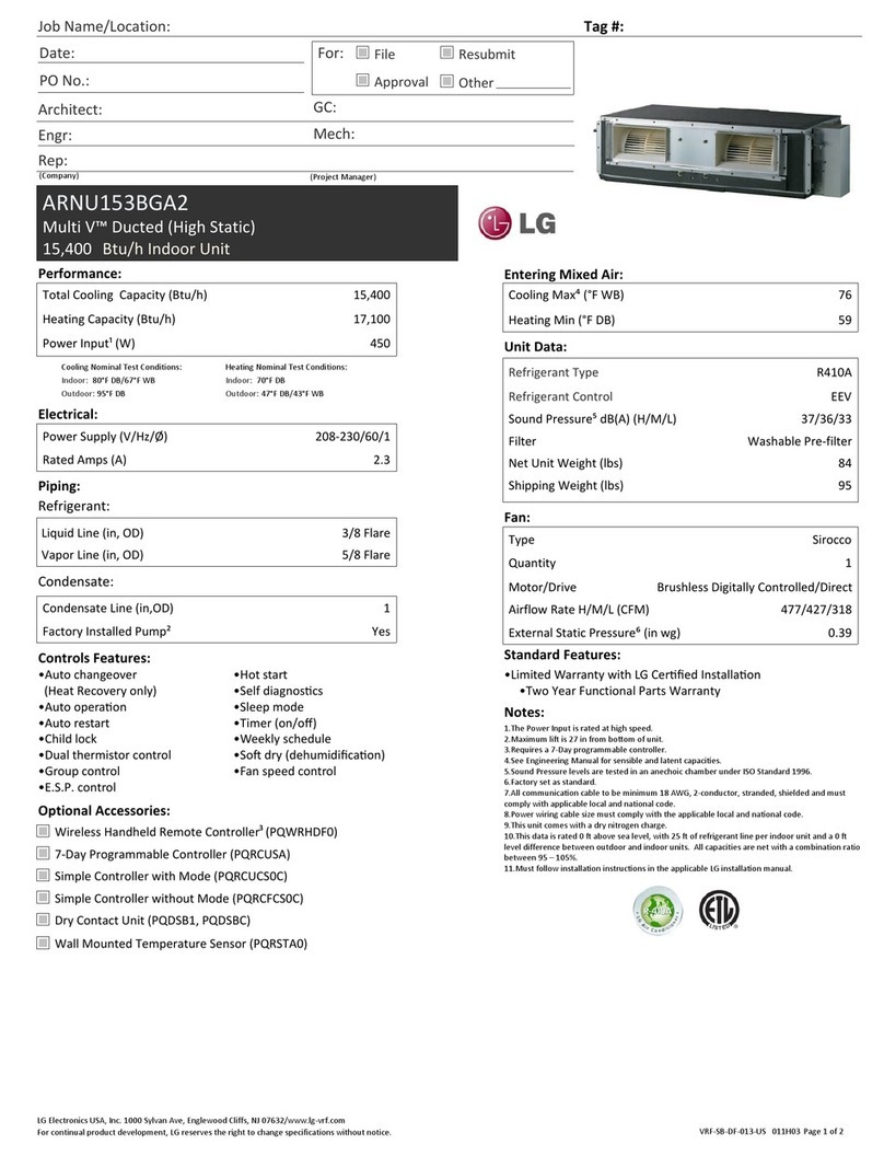
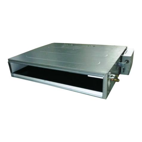
LG ZT-Q18GNLH1 User manual

OWNER'S MANUAL
AIR CONDITIONER
Before beginning installation, read these instructions
carefully. This will simplify installation and ensure that the
product is installed correctly and safely. Leave these
instructions near the product after installation for future
reference.
ENGLISH
MFL62760207
Rev.00_070523
www.lg.com
Copyright © 2023 LG Electronics Inc. All Rights Reserved.

TABLE OF CONTENTS
This manual may contain images or
content that may be different from the
model you purchased.
This manual is subject to revision by the
manufacturer.
SAFETY INSTRUCTIONS
READ ALL INSTRUCTIONS BEFORE USE...........................................................3
WARNING............................................................................................................3
CAUTION .............................................................................................................5
INSTALLATION
Location Selection..............................................................................................7
Indoor Unit Installation...................................................................................11
AFTER INSTALLATION
Test Running.....................................................................................................21
Installation Instructions ..................................................................................22

3
SAFETY INSTRUCTIONS
ENGLISH
SAFETY INSTRUCTIONS
READ ALL INSTRUCTIONS BEFORE USE
The following safety guidelines are intended to prevent unforeseen
risks or damage from unsafe or incorrect operation of the appliance.
The guidelines are separated into 'WARNING' and 'CAUTION' as
described below.
Safety Messages
WARNING
WARNING
• To reduce the risk of explosion, fire, death, electric shock, injury or
scalding to persons when installing this product, follow basic
precautions, including the following:
Technical Safety
• Installation or repairs made by unqualified persons can result in
hazards to you and others.
• The information contained in the manual is intended for use by a
qualified service technician familiar with safety procedures and
equipped with the proper tools and test instruments.
This symbol is displayed to indicate matters and operations
that can cause risk.
Read the text with this symbol carefully and follow the
instructions in order to avoid risk.
WARNING
This indicates that the failure to follow the instructions can
cause serious injuries or death.
CAUTION
This indicates that the failure to follow the instructions can
cause minor injury or damage to the appliance.

4
SAFETY INSTRUCTIONS
• Failure to carefully read and follow all instructions in the manual can
result in equipment malfunction, property damage, personal injury
and/or death.
• Compliance with national gas regulations shall be observed.
• Ducts connected to an appliance shall not contain an ignition source.
(For R32)
Installation
• Always perform grounding.
• Don't use a power cord, a plug or a loose socket which is damaged.
• For installation of the product, always contact the service center or a
professional installation agency.
• Securely attach the electrical part cover of the indoor unit and the
service panel of the outdoor unit are not attached securely, it could
result in a fire or electric shock due to dust, water, etc.
• Always install an air leakage breaker and a dedicated switching
board.
• Do not keep or use flammable gases or combustibles near the air
conditioner.
• Ensure that an installation frame of the outdoor unit is not damaged
due to use for a long time.
• Do not disassemble or repair the product randomly.
• Do not install the product at a place that there is concern of falling
down.
• Use caution when unpacking and installing.
• Do not turn on the breaker or power under condition that front panel,
cabinet, top cover, control box cover are removed or opened.
• The appliance shall be stored in a room without continuously
operating open flames (for example an operating gas appliance) and
ignition sources (for example an operating electric heater).
Operation
• Do not share the outlet with other appliances.
5
SAFETY INSTRUCTIONS
ENGLISH
• Do not use the damaged power cord.
• Do not modify or extend the power cord randomly.
• Take care so that the power cord may not be pulled during operation.
• Unplug the unit if strange sounds, smell or smoke comes from it.
• Keep the flames away.
• Take the power plug out if necessary, holding the head of the plug
and do not touch it with wet hands.
• Do not use the power cord near the heating tools.
• Do not open the suction inlet of the indoor/outdoor unit during
operation.
• Do not allow water to run into electrical parts.
• Hold the plug by the head when taking it out.
• Never touch the metal parts of the unit when removing the filter.
• Do not step on the indoor/outdoor unit and do not put anything on it.
• Do not place a heavy object on the power cord.
• When the product is submerged into water, always contact the
service center.
• Take care so that children may not step on the outdoor unit.
CAUTION
CAUTION
• To reduce the risk of minor injury to persons, malfunction, or damage
to the product or property when installing this product, follow basic
precautions, including the following:
Installation
• Install the drain hose to ensure that drain can be securely done.
• Install the product so that the noise or hot wind from the outdoor unit
may not cause any damage to the neighbors.
• Do not install the product where the noise or hot air from the outdoor
unit could cause damage the neighbors.

6
SAFETY INSTRUCTIONS
• Always inspect gas leakage after the installation and repair of
product.
• Keep level parallel in installing the product.
• Means for disconnection must be incorporated in the fixed in
accordance with the wiring rules.
• Do not install the unit in potentially explosive atmospheres.
Operation
• Avoid excessive cooling and perform ventilation sometimes.
• Use a soft cloth to clean. Do not use wax, thinner, or a strong
detergent.
- The appearance of the air conditioner may deteriorate change
color, or develop surface flaws.
• Do not use an appliance for special purposes such as preserving
animals vegetables, precision, machine, or art articles.
• Do not place obstacles around the flow inlet or outlet.
• Do not use the product for special purposes, such as preserving
foods, works of art, etc. It is a consumer air conditioner, not a
precision refrigeration system. There is risk of damage or loss or
property.

7
INSTALLATION
ENGLISH
INSTALLATION
Location Selection
Installation Places
• There should not be any heat source or steam near the unit.
• There should not be any obstacles to prevent the air circulation.
• A place where air circulation in the room will be good
• A place where drainage can be easily obtained
• A place where noise prevention is taken into consideration
• Do not install the unit near the door way.
• Ensure the spaces indicated by arrows from the wall, ceiling, or other obstacles.
• The indoor unit must keep the maintenance space.
Please use an annexed sheet or the corrugated cardboard on the bottom of packing as installation sheet.
a
Annexed sheet
b
Packing corrugated cardboard on the bottom
c
Hanging bolt location
rOrO

8
INSTALLATION
When using the bottom sheet, please use it after separating the installation sheet from packing of the
product floor by using a knife etc as a picture below.

9
INSTALLATION
ENGLISH
Required Floor Area for R32 Unit
• The appliance must be installed, operated and stored in a room with a floor area larger than the
minimum area.
• Use the graph and table to determine the minimum area.
• m : Total refrigerant amount in the system
• Total refrigerant amount : Factory refrigerant charge + Additional refrigerant amount
• A
min
: Minimum area for installation
Floor Standing Wall Mounted Ceiling Mounted
m (kg) A
min
(m
2
)m (kg) A
min
(m
2
)m (kg) A
min
(m
2
)
3
1.224 -
3
1.224 -
3
1.224 -
1.224 12.9 1.224 1.43 1.224 0.956
1.4 16.82 1.4 1.87 1.4 1.25
1.6 21.97 1.6 2.44 1.6 1.63
1.8 27.80 1.8 3.09 1.8 2.07
2 34.32 2 3.81 2 2.55
2.2 41.53 2.2 4.61 2.2 3.09
2.4 49.42 2.4 5.49 2.4 3.68
2.6 58.00 2.6 6.44 2.6 4.31
2.8 67.27 2.8 7.47 2.8 5.00
A min

10
INSTALLATION
3 77.22 3 8.58 3 5.74
3.2 87.86 3.2 9.76 3.2 6.54
3.4 99.19 3.4 11.02 3.4 7.38
3.6 111.20 3.6 12.36 3.6 8.27
3.8 123.90 3.8 13.77 3.8 9.22
4 137.29 4 15.25 4 10.21
4.2 151.36 4.2 16.82 4.2 11.26
4.4 166.12 4.4 18.46 4.4 12.36
4.6 181.56 4.6 20.17 4.6 13.50
4.8 197.70 4.8 21.97 4.8 14.70
5 214.51 5 23.83 5 15.96
5.2 232.02 5.2 25.78 5.2 17.26
5.4 250.21 5.4 27.80 5.4 18.61
5.6 269.09 5.6 29.90 5.6 20.01
5.8 288.65 5.8 32.07 5.8 21.47
6 308.90 6 34.32 6 22.98
6.2 329.84 6.2 36.65 6.2 24.53
6.4 351.46 6.4 39.05 6.4 26.14
6.6 373.77 6.6 41.53 6.6 27.80
6.8 396.76 6.8 44.08 6.8 29.51
7 420.45 7 46.72 7 31.27
7.2 444.81 7.2 49.42 7.2 33.09
7.4 469.87 7.4 52.21 7.4 34.95
7.6 495.61 7.6 55.07 7.6 36.86
7.8 522.04 7.8 58.00 7.8 38.83
Floor Standing Wall Mounted Ceiling Mounted
m (kg) A
min
(m
2
)m (kg) A
min
(m
2
)m (kg) A
min
(m
2
)

11
INSTALLATION
ENGLISH
Indoor Unit Installation
Precaution for Installing Indoor
Unit
TM/TN/TP chassis (Unit: mm)
TQ/TR chassis (Unit: mm)
• Select and mark the position for fixing bolts and
piping hole.
• Decide the position for fixing bolts slightly tilted
to the drain direction after considering the
direction of drain hose.
• Drill the hole for anchor bolt on the wall.
NOTE
• This air conditioner uses a drain pump.
• Installation the unir horizontally using a level
gauge.
• During the installation, care should be taken not
to damage electric wires.
Avoid the following installation
location.
• Such places as restaurants and kitchen where
considerable amount of oil steam and flour is
generated.
These may cause heat exchange efficiency
reduction, water drops or drain pump
malfunction.
In these cases, take the following actions;
- Make sure that ventilation fan is enough to
cover all noxious gases from this place.
- Ensure enough distance from the cooking
room to install the air conditioner in such a
place where it may not suck oily steam.
a
Air conditioner
b
Take enough distance.
c
Cooking table
d
Use the ventilation fan for smoke collecting
hood with sufficient capacity.
• Avoid installing air conditioner in such places
where cooking oil or iron powder is generated.
a
Ceiling
b
Level gauge
c
Ceiling board

12
INSTALLATION
• Avoid places where inflammable gas is
generated.
• Avoid place where noxious gas is generated.
• Avoid places near high frequency generators.
a
Haing bolt (W3/8 or M10)
b
Nut (W3/8 or M10)
c
Spring washer (M10)
d
Flat washer with insulation attached (Install
insulation to be in contact with the indoor unit
hanger part.)
e
Fla washer for M10 (Accessory)
The following parts is option.
• Hanging bolt (W3/8 or M10)
• Nut (W3/8 or M10)
• Spring washer (M10)
• Plate washer (M10)
Drill the piping hole on the wall slightly tilted to the
outdoor side using a Ø 70 hole-care drill.
4 way
a
Ceiling
b
Keep the length of the bolt from the bracket to
40 mm.
c
ceiling board
d
Air conditioner body
e
Adjust the same height
f
Paper model for installation
g
Set screw of paper model (4 pieces).
h
Open the ceiling board along the outer edge of
the paper model.
i
Keep the length of 15 ~ 18 mm between the air
conditioner bottom surface and the ceiling
surface.
j
Keep the length of 20 ~ 22 mm between the air
conditioner bottom surface and the ceiling
surface.
Drill a Hole in the Wall
Drill the piping hole with a Ø 65 mm hole core drill.
Drill the piping hole at either the right or the left
with the hole slightly slanted to the outdoor side.
a
Indoor
b
Wall
c
Outdoor
Drain Piping
• Drain piping must have down-slope (1/50 to 1/
100): Be sure not to provide up and down slope
to prevent reversal flow.
• During drain piping connection, be careful not to
exert extra force on the drain port on the indoor
unit.
• The outside diameter of the drain connection on
the indoor unit is 32 mm.

13
INSTALLATION
ENGLISH
• Piping material: Polyvinyl chloride pipe VP-25
and pipe fittings
• Be sure to execute heat insulation on the drain
piping.
Unit: mm
a
Hanging bar
a
Upward routing not allowed
- Heat insulation material: Polyethylene foam
with thickness more than 8 mm.
Drain test
The air conditioner uses a drain pump to drain
water.
Use the following procedure to test the drain pump
operation:
• Connect the main drain pipe to the exterior and
leave it provisionally until the test comes to the
end.
• Feed water to the flexible drain hose and check
the piping for leakage.
• Be sure to check the drain pump for normal
operating and noise when electrical wiring is
complete.
• When the test is complete, connect the flexible
drain hose to the drain port on the indoor unit.
CAUTION
• The supplied flexible drain hose should not be
curved, neither screwed. The curved or screwed
hose may cause a leakage of water.
a
Flexible drain hose
Heat insulation
• Use the heat insulation material for the
refrigerant piping which has an excellent heat-
resistance (over 120°C).
• Precautions in high humidity circumstance: This
air conditioner has been tested according to the
"KS Standard Conditions with Mist" and
a
Feed water
b
Drain pump
c
Drain pan
d
Drain port
e
Flexible drain hose
(Accessory)
f
Main drain pipe
g
Glue the joint.
h
Drain hose connection - Use the clip
(Accessory)

14
INSTALLATION
confirmed that there is not any default.
However, if it is operated for a long time in high
humid atmosphere (dew point tempera— ture:
more than 23°C), water drops are liable to fall. In
this case, add heat insulation mate- rial
according to the following procedure:
• Heat insulation material to be prepared...
Adiabatic EPDM or NBR with thickness 10 to
20mm.
• Stick glass wool on all air conditioners that are
located in ceiling atmosphere.
• In addition to the normal heat insulation
(thickness: more than 8mm) for refrigerant
piping (gas piping: thick piping) and drain piping,
add further 10mm to 30mm thickness material.
Circuit Breaker Detail
• All wiring must comply with local requirements.
• Select a power source that is capable of
supplying the current required by the air
conditioner.
• Use a recognized circuit breaker between the
power source and the unit. A disconnection
device to adequately disconnect all supply lines
must be fitted.
• Capacity of circuit breaker
• Warranty will be null & void if wiring is not as per
installation instructions.
Wiring Connection
• Open the control box cover and connect the
remote controller cord and indoor power wires.
• Remove the control box cover for electrical
connection between the indoor and outdoor
unit. (Remove screws
A
)
• Use the cord clamper to fix the cord.
a
Connection cord between the indoor and
outdoor unit
b
Control box cover (On which the electric
wiring connection is put.)
Model Capacity (TR/
kW) 1 Phase
ZT-
Q18GNLH1
1.5/5.15 16
ZT-Q18GPLA1 1.5/5.27 16
ZT-
Q24GNLA1
2/6.75 16
ZT-
Q24GNLH1
2/7.05 25
ZT-
Q36GNLH1
3/10.55 25
ZT-
Q48GMLH1
4/14.07 32
ZT-
Q48GMLH2
4/14.07 32
Model Capacity (TR/
kW) 1 Phase

15
INSTALLATION
ENGLISH
c
Remote controller cord
CAUTION
• The connecting cable connected to the indoor
and outdoor unit should be complied with the
following specifications. (This equipment shall
be provided with a cord set complying with the
national regulation.)
Normal cross sectional area 0.75 mm
2
• If the supply cord is damaged, it must be
replaced by a special cord or assembly available
from the manufacturer of its service agent.
• The power cord connected to the unit should be
selected according to the following
specifications.
Precaution when Laying Power
Wiring
Use round pressure terminals for connections to
the power terminal block.
a
Round pressure terminal
b
Power wire (Ground wire)
When none are available, follow the instructions
below.
• Do not connect wiring of different thicknesses to
the power terminal block. (Slack in the power
wiring may cause abnormal heat.)
• When connecting wiring which is the same
thickness, do as shown in the figure below.
Connect same thickness wiring to both sides.
Rated current of
appliance A
Nominal cross-
sectional area mm
2
3
6 0.75
4
6 and
1
10 1.0
4
10 and
1
16 1.5
4
16 and
1
25 2.5
4
25 and
1
32 4
4
32 and
1
40 6

16
INSTALLATION
• For wiring, use the designated power wire and
connect firmly, then secure to prevent outside
pressure being exerted on the terminal block.
• Use an appropriate screwdriver for tightening
the terminal screws. A screwdriver with a small
head will strip the head and make proper
tightening impossible.
• Over-tightening the terminal screws may break
them.
Connecting Cable to the Indoor
Unit
Connect the wires to the terminals on the control
board individually according to the outdoor unit
connection.
Ensure that the color of the wires of outdoor unit
and the terminal No. are the same as those of
indoor unit respectively.
Input 1-phase power supply into
outdoor & wire specification.
The power cord connected to the outdoor unit
should with the following specifications
For connection between of Indoor
and Outdoor unit & wire
specifiacation
The connecting cable connected to the Indoor and
Outdoor unit should be with the following
specifications
It is forbidden to
connect two to one
side.
It is forbidden to
connect wiring of
different thickness.
Model Capacity (TR/
kW)
1 phase
mm
2
*core
ZT-
Q18GNLH1
1.5/5.15 1.5mm
2
*3
ZT-Q18GPLA1 1.5/5.27 1.5mm
2
*3
ZT-
Q24GNLA1
2/6.75 1.5mm
2
*3
ZT-
Q24GNLH1
2/7.05 2.5mm
2
*3
ZT-
Q36GNLH1
3/10.55 2.5mm
2
*3
ZT-
Q48GMLH1
4/14.07 4mm
2
*3
ZT-
Q48GMLH2
4/14.07 4mm
2
*3
Model Capacity
(TR/kW) 1 phase No of
core
ZT-
Q18GNL
H1
1.5/5.15 0.75mm
2
4

17
INSTALLATION
ENGLISH
If the supply is damaged, it must be replaced by a
special cord or assembly available from the
manufacturer of its service agent.
WARNING
• Make sure that the screws of the terminal are
free from looseness.
Clamping of cables
1
Arrange 2 power cables on the control panel.
2
First, fasten the steel clamp with a screw to the
inner boss of control panel.
3
For the cooling model, fix the other side of the
clamp with a screw strongly.
Decorative Panel Installation
Procedure
The decorative panel has its installation direction.
Before installing the decorative panel, always
remove the paper template.
1
Remove the packing and take out air inlet grille
from front panel.
2
Remove the corner of the panel.
ZT-
Q18GPLA
1
1.5/5.27 0.75mm
2
4
ZT-
Q24GNLA
1
2/6.75 0.75mm
2
4
ZT-
Q24GNL
H1
2/7.05 0.75mm
2
4
ZT-
Q36GNL
H1
3/10.55 0.75mm
2
4
ZT-
Q48GML
H1
4/14.07 0.75mm
2
4
ZT-
Q48GML
H2
4/14.07 0.75mm
2
4
Model Capacity
(TR/kW) 1 phase No of
core

18
INSTALLATION
3
Fit the panel on the unit by inserting hooks as
shown in the picture.
4
Insert 2 screws on diagonal corners of panel.
Do not tighten the bolts completely. (The fixing
screws are included in the indoor unit box.)
Check the alignment of panel with the ceiling.
Height can be adjusted using hanging bolts as
shown in the picture. Insert the other 2 screws
and tighten all screws completely.
5
Fit the corner covers.
6
Open 2 screws of control panel cover.
7
Connect 1 display connector and 2 vane control
connectors of front panel to indoor unit PCB.
The position marking on PCB is as:
• Display connector: CN-DISPLAY
• Vane control connector: CN-VANE 1, 2

19
INSTALLATION
ENGLISH
8
Close the cover for control box.
9
Install the air inlet grille and filter on the panel.
CAUTION
• Install certainly the decorative panel.
- Cool air leakage may generate defrost.
- Water drops fall.
Good example
a
Air conditioner unit
b
Ceiling board
c
Decorative panel
d
Fit the insulator (this part) and be careful for cool air leakage
Bad example

20
INSTALLATION
a
Air conditioner unit
b
Cool air leakage (No good)
c
Ceiling board
d
Air
e
Decorative panel
This manual suits for next models
6
Table of contents
Other LG Air Conditioner manuals
Popular Air Conditioner manuals by other brands

Beko
Beko BINA 090 installation manual

Dometic
Dometic BRISK AIR 579 SERIES installation instructions

Frigidaire
Frigidaire FAS155K1A1 Factory parts catalog

QuietCool
QuietCool QC18DVS owner's manual

Mitsubishi Electric
Mitsubishi Electric City Multi Series Technical & service manual

Hitachi
Hitachi YUTAKI Series instruction manual

Dettson
Dettson COND-UHD-09 Installation instructions and homeowner's manual

Midea
Midea ATOM MDV-V28WDHN1 manual

Bryant
Bryant 14 SEER Service manual

Panasonic
Panasonic CU-NZ25VKE operating instructions

Panasonic
Panasonic S-22MF2E5A8 Service Manual & Test Run Service Manual

Panasonic
Panasonic CW-1406BU operating instructions