LG LD-2040WH User manual

DISHWASHER
SERVICE MANUAL
BEFORE SERVICING THE UNIT, PLEASE READ THIS MANUAL CAREFULLY
FOR SAFETY AND CORRECT SERVICES.
NOTE
MODEL : LD-2040WH/LD-2040SH/LD-2040MH

- 3 -
1. CAUTION......................................................................................................................... 4
2. SPECIFICATIONS ........................................................................................................... 5
3. FEATURES & TECHNICAL EXPLANATION ................................................................... 6
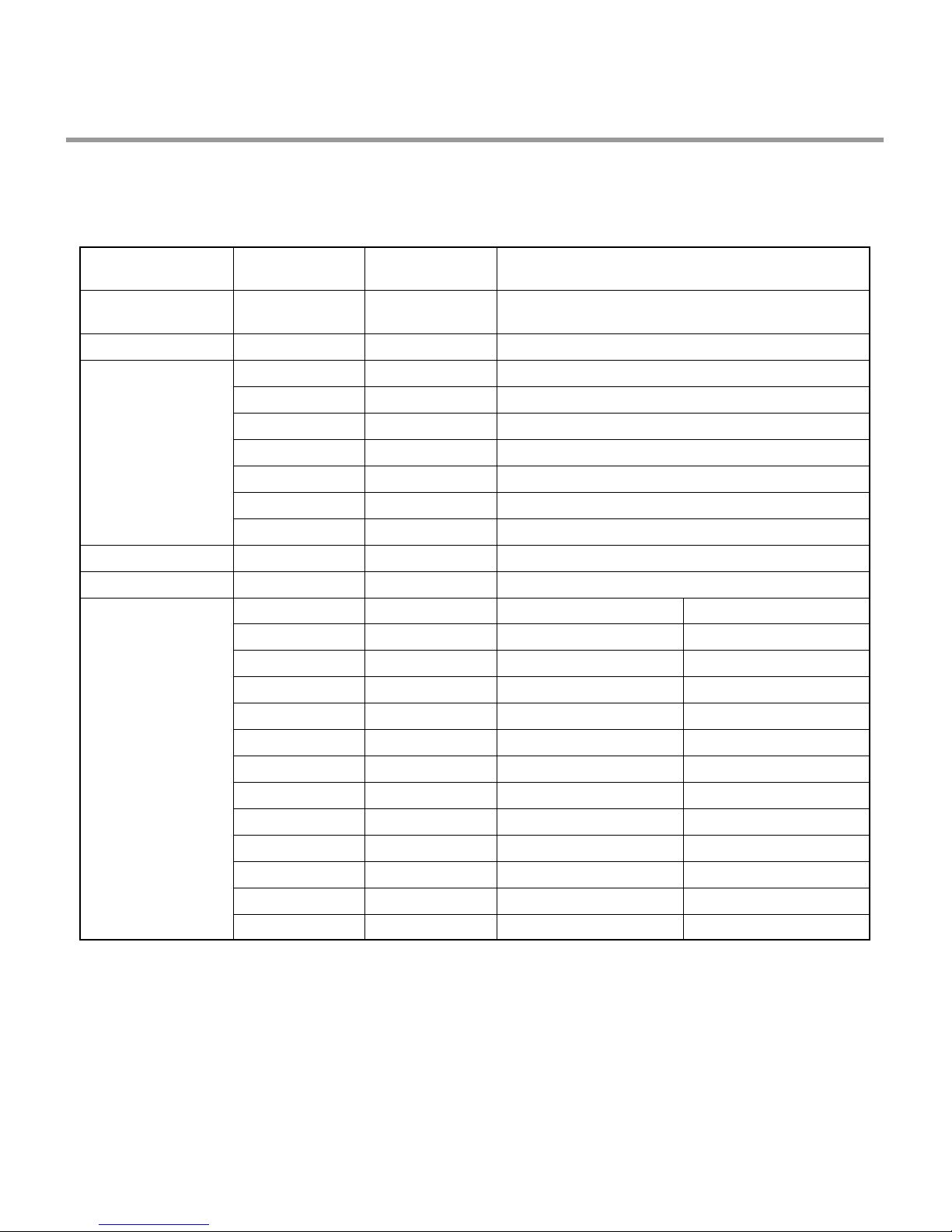
4. PARTS NAME................................................................................................................ 11
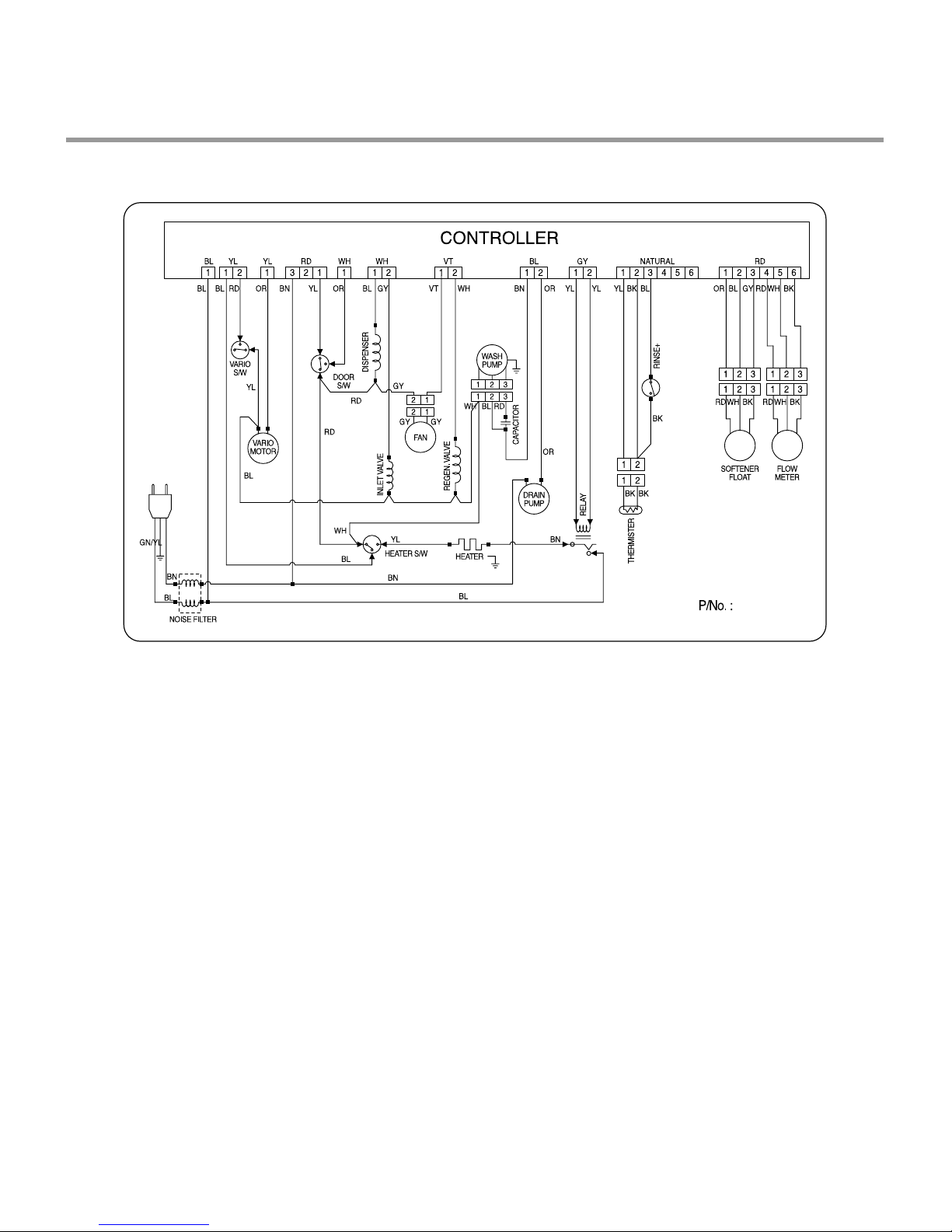
5. WIRING DIAGRAM...................................................................................................... 12
6. PROGRAM CHART (SCHEMATIC DIAGRAM)............................................................ 13
7. HOW TO DISASSEMBLE ............................................................................................ 15
7-1. FULL DISASSEMBLE .......................................................................................... 15
7-2. DISASSEMBLE C-BASE ASSEMBLY ................................................................. 23
8. TROUBLE SHOOTING METHODS.............................................................................. 26
A. TROUBLE SHOOTING ACCORDING TO DISPLAYED ERROR MESSAGE.......... 26
B. TROUBLE DIAGNOSES AND REPAIR BY SYMPTOM........................................... 28
9. INSTALLATION INSTRUCTION ................................................................................... 32
10. EXPLODED VIEW ...................................................................................................... 37
11. REPLACEMENT PART LIST ....................................................................................... 44
CONTENTS

- 4 -
�DISCONNECT POWER CORD BEFORE SERVING
�RECONNECT ALL GROUNDING DEVICES
IMPORTANT SAFETY NOTICE !
This service information is intended for individuals
possessing adequate backgrounds of electrical,
electronic and mechanical experience.
Any attempt to repair this appliance may result in
personal injury and property damage.
The manufacturer or seller can not be responsible
for the interpretation of this information, nor can it
assume any liability in connection with its use.
CAUTION !

- 5 -
2. SPECIFICATION
Rated Voltage / Frequency AC 220V/50Hz
Installation Free Standing / Built-In
Place Settings 12
Product Dimension(mm) 600(W)×600(D)×850(H)
Product Weight(Kg) 52
Door Colour White / Silver
Tub Material Stainless Steel
Control Electronic
Rated Power(Watt) 2,180
Heater Power(Watt) 2,070
Programs 6
Upper Rack Position Adjustable
Lower Rack 50% Fold down
Water Consumption(ℓ) 16 (Economy)
Power Consumption (kWh) 1.05 (Economy)
Operating Time (min) 86(Except Drying):Economy
Fan Dry System Yes
Delay Start Function Yes
Auto-Off Power Switch Yes
Process Monitor Yes
Wash Level 5
Racks Nylon Coating
Operating Water Pressure (Bar) 0.5 ~ 8
ITEM SPECIFICATION

3. FEATURES & TECHNICAL EXPLANATION
- 6 -
• Turbo fan drying system expels out hot and
humid air to enhance quick and effective
drying.
• With air mixing vent system, it expels out low
temp. steam and prevents dew drop to outside
of dishwasher.
3-1 New Technology Introduction
3-1-1. Turbo Fan Drying System
• During the high temp. Rinse course, water
temperature in an dishwasher reaches 77°C,
considerably higher than the average rinse
temperature in conventional
dishwashers(65°C). This is how Rinse 77°C
can eliminate some bacteria such as
salmonella.
3-1-2. High Temperature Rinsing
• Turbo Spray System is elaborately designed to
achieve a more powerful and efficient wash.
You can see the excellent 3 rotating spray arm
with 5 directional waterjet.
3-1-3. Turbo Spray System

- 7 -
3-2. Display Panel
REMAINING
TIME
�Indication of
remaining time
�Self diagnosis
and error
message
display
DELAY START
BUTTON
�If you want to
delay the start of
selected program,
press this button
before pressing
start button.
�Pressing the delay
time will increase
time by 1 hour.
�The delay start
time can be
adjusted from 1
hour to 19 hours.
PROGRAM
�When power
is on,
program is
automatically
set to normal.
�If you want to
change the
program,
press the
button and set
the program
you want to.
RINSE/SANI
�With each
press, rinse+,
rinse+ & 77。
C sani rinse,
77。C sani
rinse is
repeated.
START/PAUSE
BUTTON
�With each
press, Start and
Pause is
repeated during
operation.
�If the machine
remains in
Pause mode for
10 minutes, the
power is
automatically
turned off.
POWER SWITCH
BUTTON
�For operating, press
this button first for
power on.
�After operating, this
button automatically
switches off for safety
and energy saving.
�In case of irregular
surge disturbances to
the machine, the
power may be
automatically turned
off for safety.
TIME SAVE
�This function is for
saving time and
energy.
�With each press, time
save ON and OFF is
repeated.
�When select this
function, the operating
time will be shorten.
HALF LOAD
�In case of small load,
use upper or lower rack
only to save energy.
�With each press, can
select upper or lower
rack only.
�In case you don’t select
this button, the machine
always works vario
washing, which operate
upper and lower spray
arm alternately.
CHILD LOCK
�Used to lock or unlock
the control buttons to
prevent all the setting
from being changed
by children.
�For
locking/unlocking,
press Half Load and
Rinse button
simultaneously.

- 8 -
3.3 TEST MODE
CHECK PROGRAM(START IN THE STATE OF THE CLOSED DOOR)
BUTTON The number of
pushing button DISPLAY Load and Checking points
Delay start + Rinse
+ POWER S/W
Delay Start Key
Program Key
Half & Vario Key
Rinse Key
Start/Pause Key
1 TIME
1 TIME
1 TIME
2 TIME
3 TIME
5 TIME
6 TIME
7 TIME
1 TIME
1 TIME
1 TIME
2 TIME
3 TIME
4 TIME
5 TIME
6 TIME
7 TIME
8 TIME
9 TIME
10 TIME
11 TIME
12 TIME
13 TIME
n : 0H
11 : 11
12 : 22
13 : 33
14 : 44
16 : 66
17 : 77
18 : 88
19 : 99
10 : 00
n : 01
Frequency
n : 03
n : 04
n : 05
n : 06
n : 07
n : 08
n : 09
Temperature
n : 11
n : 12
n : 13
All LEDs are lighting
4 TIME 15 : 55 All LEDs are lighting
None
Flow Meter
Washing Motor
Drain Pump
Inlet Valve
Dispenser
Heater (for 10 sec.)
Fan Motor
Regeneration Valve
Thermister
Lower Nozzle
Upper Nozzle
AUTO OFF S/W
Intensive+ & Intensive
Normal
Eco
Gentle
Quick
Pre Wash
Wash 1
Wash 2
Rinse 1
Rinse 2
Dry 1
Dry 2
※Micro S/W must be ON to operate HEATER

- 9 -
4. PARTS NAME
※The appearance and specifications may be varied without notice according to localities.
Inlet Hose
1. Vapor vent
2. Control Panel
3. Door Handle
4. Front Cover
5. Lower Cover
6. Process Monitor
7. Power Switch
8. Drain Hose
9. Inlet valve ASM
10. Power Cord
11. Adjust Leg
12. Upper Rack
13. Cutlery Rack
14. Detergent & Rinse Aid Dispenser
15. Vapor Vent Cover
16. Upper Spray Arm
17. Lower Spray Arm
18. Filter ASM
19. Lower Rack
20. Salt Container Cap
Accessories
Funnel

5. WIRING DIAGRAM
- 10 -
��Non Air mixing Blower

- 11 -
6. PROGRAM CHART(SCHEMATIC DIAGRAM)
Program chart(time Flow_Vario)
Note : The figure in the process of each course means temperature of each process.
Auto Off S/W
Regen. Valve
Dispenser
Fan Motor
Heater
Inlet Valve
W/Motor
Gentle
Quick
Pre-Wash
Economy
Normal
Intensive
Intensive+ 50
20
40
20
20
26
8
15
45 45 5 10 10 10 10 18 1 1 12
2
5
5
5
5
522
25 5 101315
17 4
17 4
17 4
12 4
13
10 4
40
430
30
30
30
30
20
4
5
5
555
55
43 43 4345 4515 25 55243 432
5101520
TTTT 10 20 30
30
30
30
25
10
40
40
TTTT TTT
11
▣▣ ▣ ▣ ▣ ▣▣▣ ▣▣
14345
▣▣
1 43 9 12 14 2 55 15 15 15 15 15 18
55
55
55
55
55
45
45
▣▣ ▣▣▣▣
70 70
70
70
55
65
70
65
50
40
35
Wash
Pre Wash Main Wash Rinse 1 Rinse 2 Rinse 3 Heating Rinse Dry
DrainA Drain C Drain D DrainA DrainA DrainA DrainA Drain B
Water Supply
Water Supply
Water Supply
Water Supply
Water Supply
Water Supply
Water Supply
Water Supply
Water Supply
Water Supply
Water Supply
Water Supply
Wash
WashA
Wash B
Wash C
Wash D
Rinse
Rinse
Rinse
HeatingA
Heating B
Buzz
OFF
Stop
Stop
Stop
Stop
Stop
Stop
Stop
Stop
Stop
Stop
Stop
Stop
Stop
Drain
Drain
Drain
Drain
Drain
Drain
Drain
Drain
Drain
Drain
Drain
Drain
Dry
Drain
Rinse Dry
Finish
Drain Pump
After 1min.

7. HOW TO DISASSEMBLE
- 12 -
7-1. FULL DISASSEMBLE
BEFORE DISASSEMBLING THE DISHWASHER ;
1) Remove the plug from electric outlet to avoid electric shock.
2) Close the Water Tap(faucet).
3) Remove all dishes and items in the dishwasher.
4) Remove the Lower Rack and the Upper Rack.
5) In case of the water softner assembly model, open the water softner cap to flow out the
water to sump and drain to avoid the floor wet.
6) If necessary, remove the inlet hose and drain hose to avoid the hose damages.
7) Prepare some towels to avoid floor wet by the water left in the dishwasher.
1. Top Table
1) Remove the rear 2 screws.
2) Pull and lift the top table.
2. Low Cover
3. Cabinet-R/L
1) Cabinet-R
Remove front 4 screws.
Remove rear 3 screws.
2) Cabinet-L
Remove front 4 screws.
Remove rear 3 screws.

- 13 -
4. Balance weight
1) Remove side 4 screws.
2) Lift the balance weight.
2) Control Panel Assembly
Open the door.
Remove 4 screws(stainless).
Remove wire connection.
Be sure the wiring should not be
changed in reassembling.
Remove 3 screws for Latch assembly
Remove 5 screws for Controller.
5. Door Assembly
1) Front Cover
Open the door.
Remove 6 screws(stainless).
Close the door slowly and remove front
cover downwards.

- 14 -
3) Fan(Not on all models)
Open the door.
Remove the wire connections.
Remove the outer cover by removing 1
screw.
Remove 2 fixing screws inside and turn
the Inner Cover counterclockwise.
4) Detergent Dispenser
Close the door.
Remove the wire connections.
Remove 6 screws with brackets.
Detergent
Dispenser
Door Liner
Door Bracket
Inner
Cover
Out
Cover
Fan
5) Door Spring (Right & Left)
Push the Spring upwards and take it off
from the Frame.
Be careful not to be injured by the sharp
edge of Tub.
Take the Hinge Link off from the Hinge.
6) Door Liner
Open the door.
Remove 4 screws.
Do not use other screws for assembling.

- 15 -
6. Base spacer
Remove 4 screws.
Lift the front side of dishwasher and pull
the base spacer forward.
7. Tub assembly
1) Nozzle
Pull up the nozzle.
3) Nozzle Holder
Disconnect the water guide
Remove 4screws and lift it up
Main filter
Inner filter
Middle filter
Micro filter
2) Filter Assembly
Turn inner filter counterclockwise and lift
inner filter and middle filter.
You can disassemble inner filter and
middle filter by pulling opposite direction.
Lift up main filter.
Lift up micro filter.

- 16 -
4) Tub
Turn the air guide nut counter-clockwise.
(Special tool might be needed.)
Be careful the rubber packing of air
guide assembly should not be lost.
Turn the softner cap and nut counter-
clockwise.
Remove 4 screws for sump holder .
Remove side 8 screws.
Remove 2 Earth screw of right side.
Lift tub assembly upward.
(Be sure water softner is not blocked.)
Be careful not to be injured or scratch
floor by the sharp edge of tub.
8. Air Guide Assembly
Disconnect the wiring connection.
Remove 3 hoses assembly.
Be careful the o-ring should not be lost.
9.Water softner
1) Remove the hose assembly.
2) Lift it upward.
Be careful not to wet the floor by the
water left in the water softner.
3) You can disassemble the regeneration.
valve by unscrew the 2 screw.
Be sure not to lost the spring and bobbin.

- 17 -
5) synchronous motor
Remove the 2 screws.
Lift the cam upward.
Be careful not to install upside down.
(part number on the cam should face the
motor.)
6) Vario valve
Remove 4 screws and lift the cover
upward.
Lift the vario valve upward.
7) Capacitor
Remove 1 screw.
10. C-Base Assembly
1) Remove the screw which tighten washing
motor and base.
2) Lift them upward.
Be careful not to wet the floor by the
water left in the sump.
3) Detach the washing motor and heater
assembly by pulling opposite direction
to sump.
4) Remove the 3 screw for drain motor.

- 18 -
10) Aquastop(Not on all models)
Press the holder hook as shown in
figure.
Pull the hose assembly.
10) Inlet valve(on applicable models)
Remove 2 screws.
9) Power cord assembly
Turn the power cord assembly 90ºand
take it off.
8) Noise filter
Remove 1 screw.

- 19 -
11) Drain Hose
Press the rear side hook.
Pull the holder forward.
Pull the holder upward.
12) Relay
Remove 2 screws.

1. Top Plate
See 7-1. 1. (Page 15)
2. Low Cover
See 7-1. 2. (Page 15)
3. Cabinet-R/L
See 7-1. 3. (Page 15)
4. Air Guide
Disconnect 3 hoses assembly.
You need not to unscrew the air guide
nut.
5. Put the Dishwasher upside down.
Be careful not to be injured by the sharp edge of tub.
7-2. DISASSEMBLE C-BASE ASSEMBLY
- 20 -

- 21 -
7. Disconnect the connecting points
between tub and base
1) Disconnect noise filter.
2) Disconnect of powercord assembly.
3) Disconnect wire from the capacitor.
6. Remove the side screws
1) Remove side 8 screws.
2) Remove 2 Earth screws of right side.
3) Remove 1 motor bracket screw.
4) Lift base upward slightly.
(You can’t lift up base perfectly because of
some parts connecting to base.)
This manual suits for next models
2
Table of contents
Other LG Dishwasher manuals