LG LHB535 User manual

m
<
N
m
z
c
r-"
@Internal Use Only
Website http://biz.tgservice.com
NETWORKBLU-RAYDiSCTM
HOMETHEATERSYSTEM
@o
rll
t-
o.
r-"
ISERVICEMANUAL
EL: LH
CAUTION
BEFORE SERVICING THE UNIT, READ THE "SAFETY PRECAUTIONS"
IN THIS MANUAL.
P/NO "AFN73671926 JANUARY, 2010

CONTENTS
SECTION 1 ........ SUMMARY
SECTION 2 ........ ELECTRICAL
SECTION 3 ........ CABINET & MAiN CHASSIS
SECTION 4 ........ BCM7630 F/E LOADER PART
SECTION 5 ........ REPLACEMENT PARTS LiST
Copyright © 2010 LG Electronics inc. All right reserved. 1=1 LGE Internal Use Only
Only for training and service purposes.

SECTION 1
SUMMARY
CONTENTS
PRODUCT SAFETY SERViCiNG GUIDELINES FOR BLU=RAY DISC PLAYER PRODUCTS .............. 1-3
SERViCiNG PRECAUTIONS .......................................................................................................................... 1-4
• GENERAL SERVICING PRECAUTIONS
•INSULATION CHECKING PRODEDURE
• ELECTROSTATICALLY SENSITIVE (ES) DEVICES
SERVICE INFORMATION FOR EEPROM .................................................................................................... 1-5
1. DVD PART
2. MICOM PART
SOFTWARE UPGRADE .................................................................................................................................. 1-7
NETWORK UPDATE ....................................................................................................................................... 1-8
SPECiFiCATiONS .......................................................................................................................................... 1-11
LGE Internal Use Only 1=2 Copyright © 2010 LG Electronics inc. All right reserved.
Only for training and service purposes.

PRODUCT SAFETY SERViCiNG GUiDELiNES
FOR BLU-RAY DiSC PLAYER PRODUCTS
iMPORTANT SAFETY NOTICE
This manualwas preparedfor use only by properlytrained audio-videoservice
technicians•
When servicingthisproduct,undernocircumstancesshouldtheoriginaldesignbe
modifiedoralteredwithoutpermissionfrom LGCorporation.Allcomponentsshould
bereplacedonlywithtypesidenticaltothosein the originalcircuitandtheir physical
location,wiringand lead dressmustconformto originallayoutupon completionof
repairs•
Specialcomponentsarealsousedtopreventx-radiation,shockandfirehazard•
These componentsare indicatedbythe letter"x" includedin their componentdes-
ignatorsandarerequiredtomaintainsafeperformance.Nodeviationsareallowed
withoutpriorapprovalby LGCorporation.
Circuitdiagramsmay occasionallydifferfrom the actual circuit used. This way,
implementationofthelatestsafetyandperformanceimprovementchangesintothe
setis notdelayeduntilthenewserviceliteratureis printed.
CAUTION : Donot attemptto modifythis productin anyway. Neverperformcus-
tomized installationswithout manufacturer'sapproval.Unauthorizedmodifications
willnotonlyvoidthewarranty,butmay leadtopropertydamageor userinjury.
Serviceworkshould beperformedonlyafteryou arethoroughlyfamiliarwiththese
safetychecksandservicingguidelines.
GRAPHIC SYMBOLS
The exclamationpoint within an equilateraltriangleis intendedto
alert the service personnelto important safety informationin the
serviceliterature.
The lightningflash with arrowhead symbol within an equilateral
,_ triangleisintendedto alerttheservicepersonneltothe presenceof
noninsulated"dangerousvoltage"thatmaybeofsufficientmagnitude
toconstitutea riskof electricshock.
The pictorialrepresentationof a fuse and its ratingwithin an equi-
lateraltriangle is intendedto convey to the service personnelthe
followingfuse replacementcautionnotice:
CAUTION : FOR CONTINUEDPROTECTION AGAINST RISK
OF FIRE, REPLACEALL FUSES WITH THE SAME TYPE AND
RATINGAS MARKEDNEAREACH FUSE.
SERVICE INFORMATION
While servicing,useanisolationtransformerforprotectionfromAC lineshock.After
theoriginalserviceproblemhas beencorrected,makea checkofthefollowing:
FIRE AND SHOCK HAZARD
1. Be sure that all componentsare positionedto avoid a possibilityof adjacent
componentshorts.This isespeciallyimportantonitemstrans-portedtoandfrom
therepairshop.
2. Verifythat all protectivedevicessuch as insulators,barriers,covers,shields,
strainreliefs,powersupplycords,andotherhardwarehavebeenreinstalledper
theoriginaldesign.Be surethatthe safetypurposeofthepolarizedlineplughas
notbeen defeated.
3. Soldering must be inspectedto discover possiblecold solder joints, solder
splashes,or sharp solder points. Be certainto remove all loose foreign par-
ticles.
4. Checkfor physicalevidenceof damageor deteriorationto partsand compo-
nents, for frayed leads or damaged insulation(includingthe AC cord), and
replaceif necessary.
5. No leador componentshouldtoucha highcurrentdeviceora resistorratedat 1
wattor more.Lead tensionaroundprotrudingmetalsurfacesmustbeavoided.
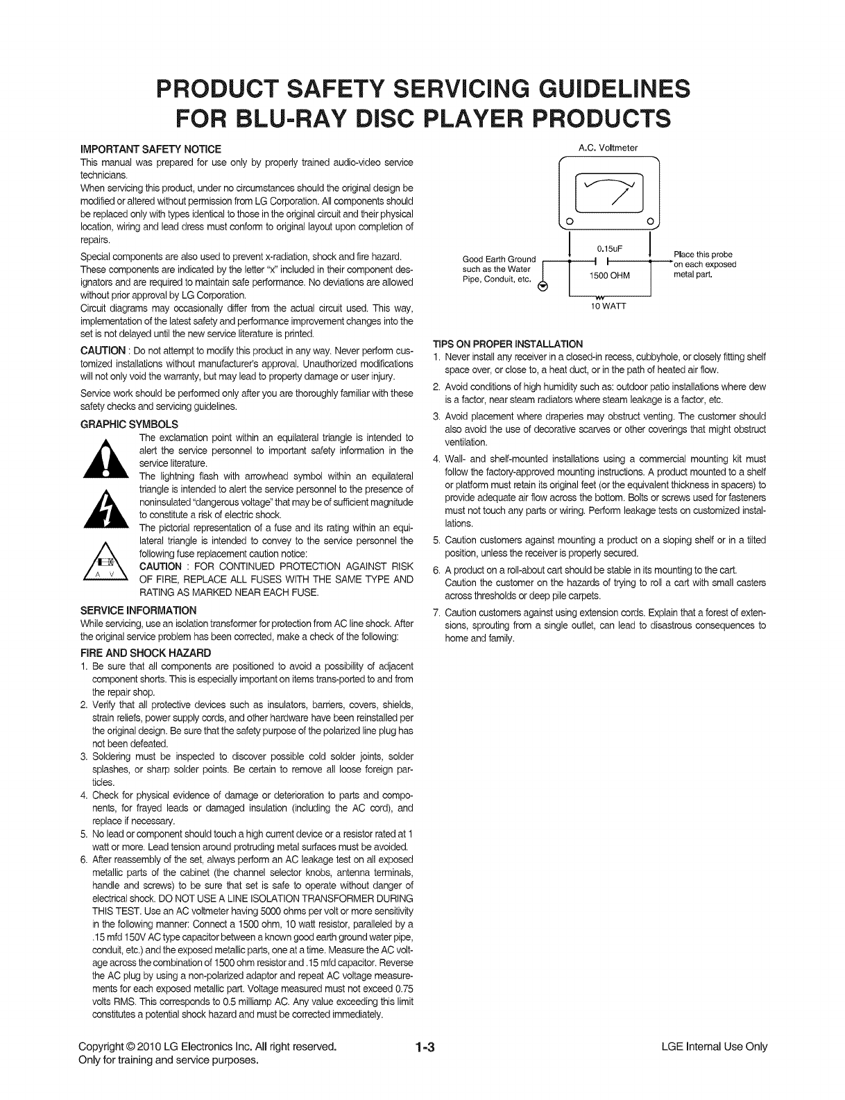
6. Afterreassemblyoftheset, alwaysperformanAC leakagetest on allexposed
metallic parts of the cabinet (the channel selector knobs, antenna terminals,
handle and screws)to be surethat set is safe to operatewithoutdanger of
electricalshock.DO NOTUSEA LINEISOLATIONTRANSFORMERDURING
THISTEST.UseanAC voltmeterhaving5000ohmspervoltormore sensitivity
in thefollowingmanner:Connecta 1500ohm, 10 wattresistor,paralleledby a
•15mfd150VACtypecapacitorbetweena knowngoodearthgroundwaterpipe,
conduit,etc.)andthe exposedmetallicparts,oneatatime.MeasuretheACvolt-
ageacrossthe combinationof 1500ohm resistorand.15 mfd capacitor.Reverse
theAC plugby using a non-polarizedadaptorand repeatACvoltage measure-
mentsfor eachexposedmetallicpart.Voltagemeasuredmustnotexceed0.75
volts RMS.Thiscorrespondsto0.5 milliampAC.Any valueexceedingthislimit
constitutesa potentialshockhazardandmustbecorrectedimmediately.
A.C. Voltmeter
Good Earth Ground _.w I]
such as the Water
Pipe, Conduit, etc. 1500 OHM
10 WATT
Place this probe
on each exposed
metal part,
TIPSON PROPERINSTALLATION
1. Neverinstallanyreceiverin aclosed-inrecess,cubbyhole,orcloselyfittingshelf
spaceover,orcloseto, aheat duct,or inthepathofheatedairflow.
2. Avoidconditionsofhighhumiditysuchas: outdoorpatioinstallationswheredew
is afactor,nearsteamradiatorswheresteamleakageisafactor,etc.
3. Avoid placementwhere draperiesmay obstructventing.The customershould
alsoavoidthe use ofdecorativescarvesor othercoveringsthatmightobstruct
ventilation.
4. Wall- and shelf-mountedinstallationsusing a commercialmounting kit must
followthe factory-approvedmountinginstructions.A productmountedto a shelf
or platformmust retainitsoriginalfeet (ortheequivalentthicknessin spacers)to
provideadequateairflow acrossthebottom.Boltsor screws usedforfasteners
must nottouch anyparts or wiring.Performleakagetestsoncustomizedinstal-
lations.
5. Cautioncustomersagainstmountinga producton a slopingshelfor in a tilted
position,unlessthe receiverisproperlysecured.
6. A producton aroll-aboutcartshouldbestablein itsmountingtothe cart.
Cautionthe customeron the hazardsof tryingto roll a cart with smallcasters
acrossthresholdsor deep pilecarpets.
7. Cautioncustomersagainstusingextensioncords.Explainthata forestofexten-
sions, sproutingfrom a singleoutlet, can lead to disastrousconsequencesto
home andfamily.
Copyright © 2010 LG Electronics Inc. All right reserved. 1=3 LGE Internal Use Only
Only for training and service purposes.

SERViCiNG PRECAUTIONS
CAUTION: Before servicing the BLU-RAY DISC PLAYER cov-
ered by this service data and its supplements and addends,
read and follow the SAFETY PRECAUTIONS. NOTE: if
unforeseen circumstances create conflict between the follow-
ing servicing precautions and any of the safety precautions in
this publications, always follow the safety precautions.
Remember Safety First :
Electrostatically Sensitive (ES) Devices
Some semiconductor (solid state) devices can be damaged
easily by static electricity. Such components commonly are
called Electrostatically Sensitive (ES) Devices. Examples of
typical ES devices are integrated circuits and some field effect
transistors and semiconductor chip components.
The following techniques should be used to help reduce the
incidence of component damage caused by static electricity.
General Servicing Precautions
1.Always unplug the BLU-RAY DISC PLAYER AC power cord 1.
from the AC power source before:
(1) Removing or reinstalling any component, circuit board,
module, or any other assembly.
(2) Disconnecting or reconnecting any internal electrical
plug or other electrical connection.
(3) Connecting a test substitute in parallel with an electro-
lytic capacitor.
Caution : A wrong part substitution or incorrect polar- 2.
ity installation of electrolytic capacitors may result in an
explosion hazard.
2. Do not spray chemicals on or near this BLU-RAY DISC
PLAYER or any of its assemblies.
3. Unless specified otherwise in this service data, clean elec-
trical contacts by applying an appropriate contact cleaning
solution to the contacts with a pipe cleaner, cotton-tipped
swab, or comparable soft applicator.
Unless specified otherwise in this service data, lubrication of
contacts is not required.
4. Do not defeat any plug/socket B+ voltage interlocks with
whitch instruments covered by this service manual might be
equipped.
5. Do not apply AC power to this BLU-RAY DISC PLAYER
and /or any of its electrical assemblies unless all sotidstate
device heat sinks are correctly installed.
6.Always connect the test instrument ground lead to an
appropriate ground before connecting the test instrument
positive lead. Always remove the test instrument ground
lead last.
Insulation Checking Procedure
Disconnect the attachment plug from the AC outlet and turn
the power on. Connect an insulation resistance meter (500V)
to the blades of the attachment plug. The insulation resistance
between each blade of the attachment plug and accessible
conductive parts (Note 1) should be more than 1Mohm.
Note 1 : Accessible Conductive Parts include Metal panels,
Input terminals, Earphone jacks,etc.
Immediately before handling any semiconductor compo-
nent or semiconductor-equipped assembly, drain off any
electrostatic charge on your body by touching a known
earth ground. Alternatively, obtain and wear a commercially
available discharging wrist strap device, which should be
removed for potential shock reasons prior to applying power
to the unit under test.
After removing an electrical assembly equipped with ES
devices, place the assembly on a conductive surface such
as aluminum foil, to prevent electrostatic charge buildup or
exposure of the assembly.
3. Use only a grounded-tip soldering iron to solder or unsolder
ES devices.
4. Use only an anti-static solder removal device. Some solder
removal devices not classified as "anti-static" can generate
electrical charges sufficient to damage ES devices.
5. Do not use freon-propetled chemicals. These can generate
an electrical charge sufficient to damage ES devices.
6. Do not remove a replacement ES device from its protective
package until immediately before you are ready to install
it. (Most replacement ES devices are packaged with leads
electrically shorted together by conductive foam, aluminum
foil,or comparable conductive material).
7. Immediately before removing the protective material from
the leads of a replacement ES device, touch the protective
material to the chassis or circuit assembly into which the
device will be installed.
Caution: Be sure no power is applied to the chassis or cir-
cuit, and observe all other safety precautions.
8. Minimize bodily motions when handling unpackaged
replacement ES devices. (Normally harmless motion such
as the brushing together of your clothes fabric or the lifting
of your foot from a carpeted floor can generate static elec-
tricity sufficient to damage an ES device.)
LGE Internal Use Only 1=4 Copyright © 2010 LG Electronics Inc. All right reserved.
Only for training and service purposes.

SERVICE iNFORMATiON FOR EEPROM
I. DVD PART
FLD "NO DISK" or "OPEN" status.
If
Remote control
Pause key-->1-->4-->7-->2 in order.
Press number 0-9, Press character
A-F (1-6 for a while)
Use arrow key (4 A _T) to
move to appropriate position and
make changes
Press pause key once
If
- Change will be applied -/_
when power
OFF-->ON.
DETECT NEW EEPROM (OPTION EDIT SCREEN)
Option Edit
Byte No. ByteO Byte1 Byte2 Byte3 Byte4 Byte5 Byte6 Byte7
[00] 55 53 O0 O0 OB 73 EB 4E
[08] AO E5 83 32 O0 O0 O0 O0
[16] 01 O0 O0 O0 01 O0 O0 O0
[24] O0 O0 O0 O0 O0 O0 O0 O0
Press UP/DOWN to change the value.
Press LEFT/RIGHT and A(Up)/D(Down) to move the cursor.
Press PAUSE to store and exit,
Copyright © 2010 LG Electronics Inc. All right reserved. 1-5 LGE Internal Use Only
Only for training and service purposes.

2. lVliCOiViPART
FLD no disc status
1,
Remote control '2' + Front 'STOP'
push same timing during 5 s
!,
FLD 'OP-0 ....
1,
Use arrow key (4 A _ T) to
move to appropriate position and
make changes
!,
Press ENTER key once
1,
FLD 'write ok' or 'up ok'
Remote control '2' + Front 'STOP'
push same timing
FLD display E2P CLR or EP CLR
Auto off
power
DETECT NEW EEPROM
OPTION EDIT SCREEN)
NAME HEX
OP0 69
OP1 B8
OP2 30
OP3 C7
OP4 00
LGE Internal Use Only 1=6 Copyright © 2010 LG Electronics inc. All right reserved.
Only for training and service purposes.

SOFTWARE UPGRADE
• Burn a DVD recordable disc or USB with a file that is named to "LG_BD_5000B30.ROM".
Insert a upgrading disc or USB.
Show help message for disc upgrade as follows.
< in the case of Back End program & Front End program >
Press play key to upgrade and it will show progress information
After completing upgrade then power is off.
Copyright © 2010 LG Electronics Inc. All right reserved. 1=7 LGE Internal Use Only
Only for training and service purposes.

NETWORK UPDATE
You can update the firmware by connecting your unit device directly to the S/W update server.
Configuring Network Settings
To update the firmware by connecting your player directly to the S/W update server, your player must be
connected to network. If your player is not connected to network, make a physical connection.
1) Press Home on the Remote Control.
2) Press 4 or I_ to select the Setup mode.
3) Select Others --> Software Update
4) On the UPDATE window, press I_ or ENTER to
check for the newest update.
(Checking will takes about one minute.)
Caution:
Pressing Enter while checking for the update will end
process
LGE Internal Use Only 1=8 Copyright © 2010 LG Electronics inc. All right reserved.
Only for training and service purposes.

if newer version exists,
5) If newer version exists, the message
"A new update was found. Do you want to
download it?" appears.
Select OK to download the update.
(Selecting CANCEL will end the update.)
6) The player starts downloading the newest update
from the SBP server.
7) When downloading is completed, the message,
"Download is complete. Do you want to
update?" appears.
8) Select OK to start updating
Copyright © 2010 LG Electronics Inc. All right reserved. 1=9 LGE Internal Use Only
Only for training and service purposes.

9) Update will be processed
Caution :
Do not turn off the power during firmware update.
10) When update is completed, the message,
"Update is complete." will appear, and the power
will turn off automatically after 5 seconds.
11) Turn the power back on.
The system now operates with the new version.
LGE Internal Use Only 1=10 Copyright © 2010 LG Electronics inc. All right reserved.
Only for training and service purposes.

SPECiFiCATiONS
• GENERAL
Power requirements:
Power consumption:
Dimensions (W x H x D):
Net Weight (Approx.):
Operating temperature:
Operating humidity:
Bus Power supply (USB):
AC 120 V, 60 Hz
150 W
Approx. 430 x 63 x 281 mm (17 x 2.5 x 11 inches) without foot
3.5 kg (7.7 Ibs)
41 °F to 95 °F (5 °C to 35 °C)
5 %to90%
DC 5V ..'=500 mA
• INPUTS /OUTPUTS
VIDEO OUT:
COMPONENT VIDEO OUT:
HDMI IN/OUT (video/audio):
ANALOG AUDIO IN:
DIGITAL IN (OPTICAL 1/2):
PORT, IN:
1.0 V (p-p), 75 f_, sync negative, RCA jack x 1
(Y) 1.0 V (p-p), 75 f_, sync negative, RCA jack x 1,
(Pb)/(Pr) 0.7 V (p-p), 75 f_, RCA jack x 2
19 pin (HDMI standard, Type A, Version 1.3)
2.0 Vrms (1 kHz, 0 dB), 600 f_, RCA jack (L, R) x 1
3 V (p-p), Optical jack x 2
0.5 Vrms (3.5 mm stereo jack)
• TUNER
FM Tuning Range:
AM Tuning Range:
87.5 to 108.0 MHz
520 to 1,710 kHz
•AMPLIFIER
Power output (4 f_), (PEAK) Total 1100 W
Front 180 W x 2
Center 180 W
Rear 180 W x 2
Sub-Woofer 200 W (Passive)
Power output (4 f_), (RMS), THD 10 % (4 f_/3 f_)
Total 980 W
Front 160 W x 2
Center 160 W
Rear 160 W x 2
Sub-Woofer 180 W (Passive)
• SYSTEM
Laser:
Signal system:
Frequency response:
Signal-to-noise ratio:
Total harmonic distortion:
Dynamic range:
LAN port:
Wireless LAN (internal antenna):
Semiconductor laser, Wavelength: 405 nm/ 650 nm
Standard NTSC color TV system
20 Hz to 20 kHz (48 kHz, 96 kHz, 192 kHz sampling)
More than 85 dB
0.05 % at 1 W
More than 95 dB
Ethernet jack x 1, 10BASE-T/100BASE-TX
Integrated IEEE 802.11 n (2.4 GHz band) wireless networking
access, compatible with 802.11 b/g Wi-Fi networks.
Copyright © 2010 LG Electronics Inc. All right reserved. 1=1 1 LGE Internal Use Only
Only for training and service purposes.

•SPEAKERS
Front speaker (Left/Right)
Type:
Impedance Rated:
Input Power:
Max. Input power:
Net Dimensions (W x H x D):
Net Weight:
Rear speaker (Left/Right)
Type:
Impedance
Input Power:
Max. Input power:
Net Dimensions (W x H x D):
Net Weight:
Center speaker
Type:
Impedance Rated:
Input Power:
Max. Input power:
Net Dimensions (W x H x D):
Net Weight:
Subwoofer
Type:
Impedance Rated:
Input Power:
Max. Input power:
Net Dimensions (W x H x D):
Net Weight:
2 Way 2 speaker
4B
180 W
360 W
109 x 196 x 78 mm (4.3 x 7.7 x 3.1 inches)
0.55 kg (1.2 Ibs)
1 Way 1 speaker
4B
180 W
360 W
109 x 196 x 78 mm (4.3 x 7.7 x 3.1 inches)
0.45 kg (0.99 Ibs)
1 Way 1 speaker
4B
180 W
360 W
400 x 118 x 83 mm (15.7 x 4.7 x 3.3 inches)
0.55 kg (1.2 Ibs)
1 Way 1 speaker
3B
200 W
400 W
198 x 385 x 275 mm (7.8 x 15.2 x 11 inches)
4.3 kg (9.5 Ibs)
LGE Internal Use Only 1=12 Copyright © 2010 LG Electronics inc. All right reserved.
Only for training and service purposes.

SECTION 2ELECTRICAL
CONTENTS
DIGITAL DISPLAY & MEDIA TRAINING MASTER ..................................................................................... 2-2
1. DISTORTED PICTURE ........................................................................................................................... 2-2
2. NO PICTURE .......................................................................................................................................... 2-7
3. PICTURE COLOR ................................................................................................................................. 2-12
4. NOISE/AUDIO PROBLEMS .................................................................................................................. 2-14
5. MISCELLANEOUS ................................................................................................................................ 2-17
6. BLU-RAY PLAYER ............................................................................................................................... 2-26
7. NETFLIX ............................................................................................................................................... 2-27
8. YouTube ................................................................................................................................................ 2-32
9. CINEMANOW ....................................................................................................................................... 2-33
10. HOME LINK .......................................................................................................................................... 2-39
11. WIRELESS NETWORK SETUP ........................................................................................................... 2-53
12. VUDU .................................................................................................................................................... 2-60
13. PICASA ................................................................................................................................................. 2-63
14. PANDORA ............................................................................................................................................. 2-64
15. ACCUWEATHER .................................................................................................................................. 2-67
ELECTRICAL TROUBLESHOOTING GUIDE ............................................................................................. 2=68
1. SMPS BOARD ...................................................................................................................................... 2-68
2. POWER KEY BOARD .......................................................................................................................... 2-70
3. FRONT BOARD .................................................................................................................................... 2-71
4. NO AUDIO CHECK ............................................................................................................................... 2-73
5. NO VIDEO CHECK ............................................................................................................................... 2-75
6. HDMI NO AUDIONIDEO CHECK (with HDMI IN) ............................................................................... 2-77
7. HDMI NO AUDIONIDEO CHECK (without HDMI IN) .......................................................................... 2-79
WAVEFORMS ................................................................................................................................................. 2=80
SYSTEM PART-1 X-TAL) .................................................................................................................... 2-80
1. SYSTEM PART-2 IDDR3 MEMORY) ................................................................................................... 2-81
3: VIDEO PART (100 YoFULL COLOR-BAR) ........................................................................................... 2-82
4. HDMI PART .......................................................................................................................................... 2-83
5. MICOM AND MPEG I/F PART .............................................................................................................. 2-84
WIRING DIAGRAM ........................................................................................................................................ 2-85
BLOCK DIAGRAM ......................................................................................................................................... 2-87
CIRCUIT DIAGRAMS .................................................................................................................................... 2-91
1. SMPS- POWER CIRCUIT DIAGRAM .................................................................................................. 2-91
2. MAIN- CPU1 CIRCUIT DIAGRAM ....................................................................................................... 2-93
3. MAIN- CPU2 CIRCUIT DIAGRAM ....................................................................................................... 2-95
4. MAIN- BAR3, NAND, CP CIRCUIT DIAGRAM ................................................................................... 2-97
5. MAIN- FRONT END CIRCUIT DIAGRAM ........................................................................................... 2-99
6. MAIN- MICOM CIRCUIT DIAGRAM .................................................................................................. 2-101
7. MAIN- HDMI CIRCUIT DIAGRAM ..................................................................................................... 2-103
8. MAIN- ADC, Dim CIRCUIT DIAGRAM .............................................................................................. 2-105
9. MAIN- DSP CIRCUIT DIAGRAM ....................................................................................................... 2-107
10. MAIN- POWER CIRCUIT DIAGRAM ................................................................................................. 2-109
11. MAIN- I/O CIRCUIT DIAGRAM .......................................................................................................... 2-111
12. AMP1 CIRCUIT DIAGRAM ................................................................................................................. 2-113
13. AMP2 CIRCUIT DIAGRAM ................................................................................................................. 2-115
14. FRONT CIRCUIT DIAGRAM .............................................................................................................. 2-117
15. FRONT JACK CIRCUIT DIAGRAM .................................................................................................... 2-119
16. IPOD CIRCUIT DIAGRAM .................................................................................................................. 2-121
17. WiFi- USB_GPIO_STRAP CIRCUIT DIAGRAM (OPTION) .............................................................. 2-123
18. WiFi- POWER & CONTROL CIRCUIT DIAGRAM (OPTION) ........................................................... 2-125
19. WiFi- RF ANTENNA CIRCUIT DIAGRAM (OPTION_ 2-127
20. WIRELESS TX MODULE CIRCUIT DIAGRAM (OP-V:::::::::::::::::::::::::::::::::::::::::::::::::::::::::::::::::::::: 2-129
CIRCUIT VOLTAGE CHART ...................................................................................................................... 2-131
PRINTED CIRCUIT BOARD DIAGRAMS .................................................................................................. 2-133
1. MAIN P.C.BOARD .............................................................................................................................. 2-133
2. SMPS P.C.BOARD ............................................................................................................................. 2-137
3. AMP P.C.BOARD ................................................................................................................................ 2-139
4. FRONT P.C.BOARD ........................................................................................................................... 2-141
5. FRONT JACK P.C.BOARD ................................................................................................................. 2-143
6. IPOD P.C.BOARD ............................................................................................................................... 2-143
Copyright © 2010 LG Electronics Inc. All right reserved. 2-1 LGE Internal Use Only
OnJy for training and service purposes.

DiGiTAL DISPLAY & MEDIA TRAiNiNG MASTER
Objective: To provide clear and concise guidelines for customer service agents to handle calls on
box goods calls.
1. DISTORTED PICTURE
1-1. Lines on Picture
Distorted picture refers to the customer getting video, but there is a problem with the video.
What cables is
the customer using to
connect the BD?
YES
Is the TV set
to the correct input?
IYES
Do lines appear when
watching multiple discs?
YES
Do lines appear when
watching a TV program?
YES
Do lines appear
when the BD is
connected to another TV?
YES
Has the customer tried
another set of cables?
Determine what cables the customer is using to connect
the BD to the TV and if connected properly. Refer to OM for
connections. Tighten any loose cables. Make sure the customer
is not connecting a BD to VCR or BD to DVD Recorder.
Copy protection can distort the picture on older DVD models.
Make sure the TV is on the correct input.
Turn TV off, then on to determine input.
Video when using composite, or component.
DVl when using DVl, and HDMI when using HDMI.
One disc displaying the issue is a problem with the disc.
Multiple discs displaying the problem could indicate the BD lens
needs to be cleaned. Recommend the customer use a lens
cleaner on the BD. A lens cleaner is available at any local
electronics retailer.
Lines appearing when watching a TV program indicates
an issue with the display. If the TV program is fine,
then connect the BD to another input on the display to
determine if the problem is following the BD.
Connect the BD to another TV and play a disc.
No lines during disc play back indicates a problem with the first TV.
Please refer to the owners manual for instructions on how to
connect the BD to a TV. If the BD has a problem on the
second TV, then see service chart for service information.
Have the customer try another set of cables. A bad cable can
also cause video problems. Test the cable with another device to
the TV to also determine if the TV is bad. If BD is problem,
please see service chart for service information.
LGE internal Use Only 2-2 Copyright © 2010 LG Electronics inc. All right reserved.
Only for training and service purposes.

DiGiTAL DISPLAY & MEDIA TRAiNiNG MASTER
1=2. Ghost Picture
Distorted picture refers to the customer getting video, but there is a problem with the video.
What cables is the customer
using to connect the BD?
IYES
Is the TV set to
the correct input?
IYES
Do ghosting appear when
watching multiple discs?
YES
Do lines appear when
watching a TV program?
YES
Does ghosting
appear when the BD is
connected to another TV?
YES
Has the customer tried
another set of cables?
NO
NO
NO
NO
NO
NO
l Determine what cables the customer is using to connect the BD to
the TV and if connected properly. Refer to OM for connections.
Tighten any loose cables. Make sure the customer is not connecting a
BD to VCR or BD to DVD Recorder. Copy protection can distort
the picture on older VCR models.
Make sure the TV is on the correct input. Turn TV off,
then on to determine input. Video when using composite,
or component. DVl when using DVl, and HDMI when using HDMI.
IOne disc displaying the issue is a problem with the disc.
Multiple discs displaying the problem could indicate the BD lens
needs to be cleaned. Recommend the customer use a lens cleaner
on the BD. A lens cleaner is available at any local electronics retailer.
IGhosting appearing when watching a TV program indicates an
issue with the display. If the TV program is fine, then connect
the BD to another input on the display to determine
if the problem is following the BD.
f Connect the BD to another TV and play a disc.
No ghosting during disc play back indicates a problem with the first TV.
Please refer to the owners manual for instructions on how to
connect the BD to a TV. If the BD has a problem on the second TV,
then see service chart for service information.
Have the customer try another set of cables. A bad cable can
also cause video problems. Test the cable with another device to
the TV to also determine if the TV is bad. If BD is problem,
please see service chart for service information.
Copyright © 2010 LG Electronics Inc. All right reserved. 2=3 LGE Internal Use Only
Only for training and service purposes.

DiGiTAL DISPLAY & MEDIA TRAiNiNG MASTER
1=3. Rolling Picture
Distorted picture refers to the customer getting video, but there is a problem with the video.
What cables is the customer
using to connect the BD?
IYES
Is the TV set to
the correct input?
IYES
Does rolling appear when
watching multiple discs?
YES
Does rolling appear when
watching a TV program?
YES
Does rolling appear
when the BD is connected to
another TV?
YES
Has the customer tried
another set of cables?
NO
NO
NO
NO
NO
NO
l Determine what cables the customer is using to connect the BD to
the TV and if connected properly. Refer to OM for connections.
Tighten any loose cables. Make sure the customer is not connecting
a BD to VCR or BD to DVD Recorder. Copy protection can distort
the picture on older VCR models.
Make sure the TV is on the correct input. Turn TV off,
then on to determine input. Video when using composite,
or component. DVl when using DVl, and HDMI when using HDMI.
IOne disc displaying the issue is a problem with the disc.
Multiple discs displaying the problem could indicate the BD lens
needs to be cleaned. Recommend the customer use a lens cleaner
on the BD. A lens cleaner is available at any local electronics retailer.
Rolling appearing when watching a TV program indicates
an issue with the display. If the TV program is fine, then connect
the BD to another input on the display to determine if the problem
is following the BD.
fConnect the BD to another TV and play a disc. No lines during disc play
back indicates a problem with the first TV. Please refer to the owners
manual for instructions on how to connect the BD to a TV. If the BD has a
problem on the second TV, then see service chart for service information.
Have the customer try another set of cables. A bad cable can also
cause video problems. Test the cable with another device to the TV
to also determine if the TV is bad. If BD is problem,
please see service chart for service information.
LGE internal Use Only 2-4 Copyright © 2010 LG Electronics inc. All right reserved.
Only for training and service purposes.

DiGiTAL DISPLAY & MEDIA TRAiNiNG MASTER
1=4. Shaky Picture
Distorted picture refers to the customer getting video, but there is a problem with the video.
What cables is the customer
using to connect the BD?
IYES
Is the TV set to
the correct input?
IYES
Does shaking appear when
watching multiple discs?
YES
Does shaking appear when
watching a TV program?
YES
Does shaking appear
when the BD is connected to
another TV?
YES
Has the customer tried
another set of cables?
NO
NO
NO
NO
NO
NO
l Determine what cables the customer is using to connect the BD to
the TV and if connected properly. Refer to OM for connections.
Tighten any loose cables. Make sure the customer is not connecting a
BD to VCR or BD to DVD Recorder. Copy protection can distort
the picture on older VCR models.
Make sure the TV is on the correct input. Turn TV off, then on
to determine input. Video when using composite, or component.
DVl when using DVl, and HDMI when using HDMI.
IOne disc displaying the issue is a problem with the disc.
Multiple discs displaying the problem could indicate the BD lens
needs to be cleaned. Recommend the customer use a lens cleaner
on the BD. A lens cleaner is available at any local electronics retailer.
Shaking appearing when watching a TV program indicates
n issue with the display. If the TV program is fine, then connect
the BD to another input on the display to determine if the problem
is following the BD.
f Connect the BD to another TV and play a disc. No shaking during
disc play back indicates a problem with the first TV. Please refer to
the owners manual for instructions on how to connect the BD to a TV.
If the BD has a problem on the second TV,
then see service chart for service information.
Have the customer try another set of cables. A bad cable can
also cause video problems. Test the cable with another device to
the TV to also determine if the TV is bad. If BD is problem,
please see service chart for service information.
Copyright © 2010 LG Electronics Inc. All right reserved. 2=5 LGE Internal Use Only
Only for training and service purposes.

DiGiTAL DISPLAY & MEDIA TRAiNiNG MASTER
1=5. Blurry Picture
Distorted picture refers to the customer getting video, but there is a problem with the video.
What cables is the customer
using to connect the BD?
IYES
Is the TV set to
the correct input?
IYES
Does blurriness appear when
watching multiple discs?
YES
Does blurriness appear when
watching a TV program?
YES
Does blurriness appear
when the BD is connected to
another TV?
YES
Has the customer tried
another set of cables?
NO
NO
NO
NO
NO
NO
l Determine what cables the customer is using to connect the BD to
the TV and if connected properly. Refer to OM for connections.
Tighten any loose cables. Make sure the customer is not connecting
a BD to VCR or BD to DVD Recorder. Copy protection can distort
the picture on older VCR models.
Make sure the TV is on the correct input. Turn TV off,
then on to determine input. Video when using composite, or component.
DVl when using DVl, and HDMI when using HDMI.
IOne disc displaying the issue is a problem with the disc.
Multiple discs displaying the problem could indicate the BD lens
needs to be cleaned. Recommend the customer use a lens cleaner on
the BD. A lens cleaner is available at any local electronics retailer.
fBlurriness appearing when watching a TV program indicates an
issue with the display. If the TV program is fine, then connect
the BD to another input on the display to determine if the problem
is following the BD.
f Connect the BD to another TV and play a disc. No blurriness
during disc play back indicates a problem with the first TV.
Please refer to the owners manual for instructions on how to connect
the BD to a TV. If the BD has a problem on the second TV,
then see service chart for service information.
I Have the customer try another set of cables.
>_ A bad cable can also cause video problems. Test the cable with another
_device to the TV to also determine if the TV is bad. If BD is problem, please
l see service chart for service information.
LGE internal Use Only 2=6 Copyright © 2010 LG Electronics inc. All right reserved.
Only for training and service purposes.

DiGiTAL DISPLAY & MEDIA TRAiNiNG MASTER
2. NO PICTURE
2=1. Black Screen
The entire screen is black.
Does the BD on-screen
menu appear?
YES
What cables is the customer
using to connect the BD?
YES
Is the TV set to
the correct input?
YES
Is the customer able to
watch TV programming?
YES
Can the customer connect
the BD to another TV?
YES
Has the customer tried
another set of cables?
NO
NO
NO
NO
NO
NO
I Make sure the customer did not select 480i resolution in the menu |
]
_ of the BD player if using HDMI connections. Change resolution on t
_upconversion BD player by pushing the resolution button of the remote con
troller. HDMI don't support 480i resolution.
f Determine what cables the customer is using to connect the BD to
the TV and if connected properly. Refer to OM for connections.
Tighten any loose cables. Make sure the customer is not connecting a
BD to VCR or BD to DVD Recorder. Copy protection can distort
the picture on older VCR models.
fMake sure the TV is on the correct input. Turn TV off,
then on to determine input. Video when using composite, or component.
DVl when using DVl, and HDMI when using HDMI.
If the customer is not able to watch television then he may have a
problem with his television, especially if the cable signal comes
through on a different input. If the customer can not get a TV program,
then he still may have a problem with the particular input on his TV.
fHave the customer connect the BD to another TV in order to
determine if the problem is the BD or the TV. Refer to the OM for
connections assistance. If the BD works on the second TV,
then the customer has a problem with his TV.
fHave the customer try another set of cables. A bad cable can
also cause video problems. Test the cable with another device to the TV
to also determine if the TV is bad. If BD is problem, please see
service chart for service information.
Copyright © 2010 LG Electronics Inc. All right reserved. 2-7 LGE Internal Use Only
Only for training and service purposes.
Other manuals for LHB535
4
Table of contents
Other LG Home Theater System manuals