LG LMV1940DW User manual

P/NO. 3828W5U0357
Printed in Korea
LMV1940DW
LMV1940DB
INSTALLATION INSTRUCTIONS
PLEASE READ AND SAVE THESE INSTALLATION INSTRUCTIONS.
website: http://www.lg.ca

YOUR SAFETY FIRST
BEFORE YOU START
• Proper installation is the installer's responsibility!
– Read the entire manual be ore you begin. The Model number label is located on the oven ront.
See Figure 1. Mounting plate is located on back side o microwave oven. See Figure 2.
BE SURE TO READ THE FOLLOWING SAFETY INSTRUCTIONS:
FOR YOUR SAFETY:
• You will need TWO people to install this oven. It is heavy and could cause personal injury i not handled
properly. The dimensions o the oven are as ollows:
Height : 16 7/16 inches
Width : 29 15/16 inches
Depth : 15 5/8inches
Weight : 60 lbs.
• Avoid Electrical Shock!
– Be ore you drill into the wall, note where electrical outlets are and where electrical wires might be concealed
behind the wall. YOU COULD GET AN ELECTRIC SHOCK i you contact electrical wires
with your drill bit.
– Locate and disconnect the power to any electrical circuits that could be a ected by installing this oven.
IF YOU DO NOT DISCONNECT THE POWER, YOU COULD GET AN ELECTRIC SHOCK.
• ELECTRICAL RATING OF THIS OVEN : 120V AC 60Hz.
13 Amp / 1,500 W (Microwave oven + Cooktop Lamps + Ventilation Fan)
– You need a DEDICATED 120V, 60Hz, AC only, 15 or 20A, used electrical supply (located in the cabinet
above the microwave as close as possible to the microwave) serving only the microwave.
— 2 —
Mounting
plate
( Remove from
oven to install. )
Back of oven
Figure 1 Figure 2
Model Number Label
WARNING

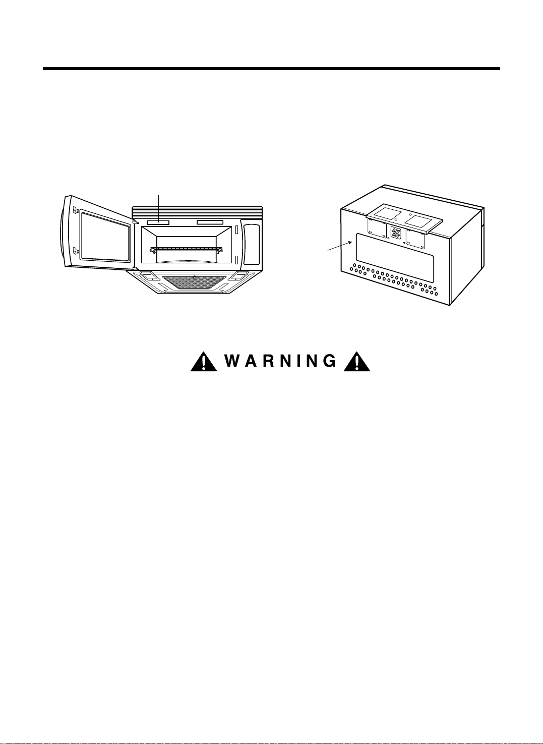
• THIS APPLIANCE MUST BE GROUNDED!
– I there is an electrical short circuit, grounding reduces the risk o electrical shock by providing an escape
wire or the electric current. This appliance is equipped with a cord having a grounding wire with a grounding
plug.
• Place the plug into a properly installed and grounded outlet. See Figure 3.
• Do not use an extension cord.
• Keep the power cord dry and do not pinch or crush it.
• DO NOT, UNDER ANY CIRCUMSTANCES, REMOVE THE
POWER SUPPLY CORD GROUNDING PRONG!
This appliance MUST be grounded!
I you use the grounding plug improperly, you risk electric shock!
– Check with a quali ied electrician i you are not sure whether the oven is properly grounded or i you do not
completely understand the grounding instructions.
DO NOT USE A FUSE IN THE NEUTRAL OR GROUNDING CIRCUIT.
Improper grounding could result in electric shock or other personal injury.
SAVE THESE INSTRUCTIONS FOR THE LOCAL ELECTRICAL INSPECTOR'S USE.
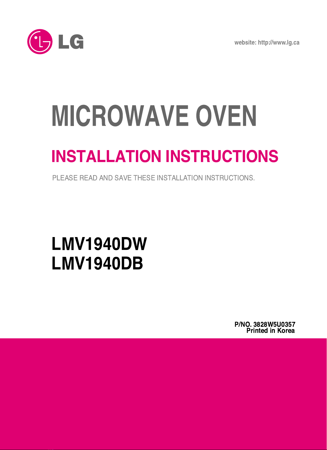
• DO NOT EXPOSE YOURSELF TO EXCESSIVE MICROWAVE ENERGY!
– DO NOT try to operate the microwave oven with the door open.
– DO NOT tamper with or de eat the sa ety interlocks.
– DO NOT place objects between the microwave oven ront ace and the door.
–
DO NOT allow soil or cleaner residue to build up on the lat sur aces around the microwave oven door.
– DO NOT operate the microwave oven i it is damaged.
– The microwave oven door must close properly to operate sa ely.
– DO NOT USE THE MICROWAVE OVEN:
• I the door is bent.
• I the hinges or latches are broken or loose.
• I the door seals, sealing sur aces or glass is broken.
– DO NOT ATTEMPT TO ADJUST OR REPAIR THE OVEN YOURSELF!
It should be adjusted and repaired by a quali ied technician who can check or microwave leakage a ter
repairing the oven.
I you do not use the microwave oven as instructed,
you could be exposed to excessive microwave energy.
YOUR SAFETY FIRST
— 3 —
PROPERLY POLARIZED AND
GROUNDED OUTLET
Three-Pronged (Grounding) Plug
Figure 3
WARNING
WARNING
WARNING

• MAKE SURE YOU HAVE ENOUGH SPACE AND SUPPORT.
– Mount the oven against a lat, vertical wall, so it is supported by the wall. The wall should be constructed o
minimum 2" x 4" wood studding and 3/8" thick drywall or plaster/lath.
– ATTACH AT LEAST ONE o the two lag screws supporting the oven to a vertical, 2" x 4" wall stud.
– DO NOT mount the microwave oven to an island or peninsula cabinet.
– BE SURE the upper cabinet and rear wall structures are able to support 150 lbs., plus the weight o any
items you place inside the oven or upper cabinet.
– Locate the oven away rom strong dra t areas, such as windows, doors, and strong heating vents.
– BE SURE you have enough space. See Figure 4 below or minimum vertical and horizontal clearance.
I you do not mount the oven as instructed,
you risk personal injury and/or property damage.
CAUTION
• Be ore you begin installing the oven, PLACE A PIECE OF THE CARTON OR OTHER HEAVY
MATERIAL (a blanket) over the countertop or cooktop to protect it. Do not use a plastic cover.
Failure to protect these sur aces could result in property damage.
YOUR SAFETY FIRST
— 4 —
30" min. cabinet opening width
30" min. clearance from bottom
of cabinet to coo ing surface
or countertop
(Use templates included
with installation instructions)
Grounded Outlet
(inside upper cabinet)
Power Supply Cord Hole
Figure 4
WARNING

THE FOLLOWING PARTS ARE SUPPLIED WITH THE OVEN:
NOTE: Depending on your ventilation requirements, you may not use all o these parts.
NOTE: You need to install at least one lag screw into a 2" x 4" stud and our anchor bolts into the wall.
The mounting area must meet the 150 lbs. weight requirement.
— 5 —
Damper/duct connector
(for roof-venting or wall-venting installation)
Not Actual Size
One power cord clamp and
One dark-colored mounting screw
(to hold the power cord)
Actual Size
Two tapping screws
- Actual Size
(for attaching the damper duct connector)
Four 1/4" x 2" lag screws
- Actual Size
(for wall stud holes)
Two 1/4" x 2" bolts
- Actual Size
(for securing to the upper cabinet)
Four spring toggle heads
- Actual Size
(for the toggle bolts)
Two washers
- Actual Size
(for the two upper cabinet bolts)
Four 1/4" x 3" toggle bolts
- Actual Size
(for drywall holes)
One power cord clamp bushing
- Actual Size
(for the cord hole in a metal upper cabinet)
One lock pin and one washer
-Not Actual size
PARTS, TOOLS, MATERIALS

YOU WILL NEED THE FOLLOWING TOOLS AND MATERIALS FOR THE INSTALLATION:
Carton or other heavy material or covering the counter top.
• I you have brick or masonry walls, you will need special hardware and tools.
• The ductwork you need or the installation is not included. All wall and roo caps must have a back-dra t
damper.(Shown on page 5.)
PARTS, TOOLS, MATERIALS
— 6 —
Clear tape
( or taping the templates to the wall) Stud inder or thin nail.
Saber saw ( or cutting vent
holes or roo or wall venting)
Keyhole saw ( or the power cord hole)
Electric drill
3/8" and 3/4" wood drill bits
1/2" and 3/16"
drill bits
Phillips screwdriver ( or the screws)
Pencil
Flat blade screwdriver ( or the toggle bolts)
Measuring tape (metal pre erred)
Small side cutters or tin snips Caulking gun
Plumb line
Duct Tape

AVOID ELECTRICAL SHOCK! THIS APPLIANCE MUST BE GROUNDED!
1. Locate the grounded electric outlet or this oven in the cabinet
above the oven, as shown in Figure 4.
NOTE: The outlet should be on a circuit dedicated to the
microwave oven 120V, 60Hz., AC only with a
20A used electrical supply.
IMPORTANT: I you do not have the proper wall outlet, you MUST
have one installed by a quali ied electrician.
2. You will cut the power-supply-cord hole (shown in
Figure 4) later when you prepare the wall and upper cabinet in
Step 4.
NOTE: Do not use an extension cord.
Keep the power cord dry and do not pinch or crush it.
Improper grounding could result in
electric shock or other personal injury.
• DO NOT, UNDER ANY CIRCUMSTANCES, REMOVE THE POWER SUPPLY
CORD GROUNDING PRONG! This appliance MUST be grounded!
STEP 1: PREPARE THE
ELECTRICAL CONNECTIONS
— 7 —
Grounded Outlet
( Inside Cabinet )
Upper
Cabinet
Power-Supply-Cord Hole
Figure 4
WARNING
WARNING

NOTE: The ductwork you need or outside ventilation is not included with your oven. The standard ductwork
ittings and length are shown in Figure 9, page 9.
THIS OVEN MUST BE PROPERLY VENTED!
You may vent your oven in one o three ways:
Roo -venting I your oven is located on an outside wall near the roo , as in Figures 6 (31/4" x
10" duct) and 8 (6" round duct.)
Wall-venting I your oven is located on an outside wall on the irst loor o your house, as in Figure
5 (31/4" x 10" duct) and Figure 8 (6" round duct.)
Room-venting I your oven is located on an inside wall o your house, as in Figure 7.
NOTE: I you choose the rear exhaust method (roo -or wall-venting), be sure there is enough clearance within
the wall or the exhaust duct.
REMEMBER AS YOU INSTALL THE VENTING:
• Keep the length o the ductwork and the
number o elbows to a minimum to
ventilate your oven e iciently.
See examples on page 9.
• Keep the size o the ductwork the same.
• Do not install two elbows together.
• Use duct tape to seal all joints in the duct
system.
• Use caulking to seal the exterior wall or
roo opening around the cap.
STEP 2:
PREPARE THE VENTING SYSTEM
— 8 —
Wall Venting
Wall venting
through-the-wall
wall cap
3 1/4"x10"
duct
Figure 5
cabinet
oven
Roof Venting
through-the-roof
3 1/4"x10"
duct
Figure 6
roof cap
Roof venting
cabinet
oven
6" min.
diameter
round duct
3 1/4" to round
duct transition
3 1/4" to round
ductwork transition
Figure 8
roof cap
wall cap
elbow
WARNING-FIRE HAZARD
Room Venting
Figure 7
cabinet
oven

STEP 2:
PREPARE THE VENTING SYSYTEM
STANDARD FITTINGS
NOTE: I the existing duct is round, you must use a rectangular-to-round adapter, with a rectangular 3"
extension duct installed between the damper assembly and the adapter to prevent the exhaust
damper’s sticking.
DUCT LENGTH
The total length o the duct system, including straight duct, elbows, transitions, wall or roo caps must not
exceed the equivalent o 140 eet.
For best per ormance, do not use more than three 90 degree elbows.
Below are the standard ittings and their equivalent length in eet.
To calculate the equivalent length o each ductpiece used, see the examples below.
— 9 —
Figure 9
1
4567
23
3 1/4"x10"
to 6"=5ft.
90û elbow
=10ft. 45û elbow
=5ft.
3 1/4"x10"
wall cap
=40ft.
3 1/4"x10"
flat elbow
=10ft.
3 1/4"x10" roof
cap=24ft. 3 1/4"x10" 90û
elbow=25ft.
Examples
For 3 1/4"x10" SYSTEMS
1-3 1/4" x 10" 90û elbow
1-Wall Cap
8 feet straight duct
TOTAL LENGTH
1-transition
2-90û elbows
1-Wall Cap
8 feet straight
TOTAL LENGTH
For 6" ROUND SYSTEMS
6ft.
2ft. 2ft.
3 1/4"x10"
90û elbow wall cap 6ft.
90û elbows
transition
wall cap
= 25 ft.
= 40 ft.
= 8 ft.
= 73 ft.
= 5 ft.
= 20 ft.
= 40 ft.
= 8 ft.
= 73 ft.

Your microwave oven is shipped with the blower assembled or roo venting. You need to adjust the blower i
you want wall-venting or room-vented (recirculating) installation.
ELECTRICAL SHOCK HAZARD! UNPLUG UNIT BEFORE WORKING ON IT.
• DO NOT PULL OR STRETCH THE BLOWER WIRING! Pulling and stretching the blower wiring could result in
electrical shock.
REMOVE THE MOUNTING PLATE:
1. Remove any shipping materials and parts rom inside
the microwave oven.
2. Cover the counter top or cooktop with a thick,
protective covering to protect it rom damage and
dirt. See Figure 10.
NOTE: I you have a ree-standing range, disconnect
it, move it onto a piece o cardboard or
hardboard and pull it away rom the wall, so
that you can get closer to the upper cabinet
and back wall or easier measuring and
drilling.
3. Remove mounting plate screw(s) (1 or 2 screws)
rom the mounting plate as shown and discard.
(See Figure 11.)
4. This plate will be used as the rear mounting plate.
(It will be used to locate and mark the mounting
holes on the rear wall.)
5. Locate exhaust adaptor, grease ilters and hardware
packet.
6. At this point, remove any adhesive tape (i there is
any), on the exhaust adaptor, the grease ilters and
the power supply cord.
ROOF-VENTED INSTALLATION:
This oven is shipped assembled or roo -vented. You
will need to install the exhaust adaptor regardless o
cabinet.
1. Attach the exhaust adaptor to the blower plate by
sliding it into the guides. (See Figure 12.)
STEP 3:
PREPARE THE VENTING BLOWER
— 10 —
Figure 10
A thick, protective
covering
Figure 11
Mounting
plate
Mounting plate
screw(s)
(1 or screws)
Control panel side
Figure 12
Back
of oven
Exhaust
adaptor
WARNING

WALL-VENTED INSTALLATION:
1. Remove one blower unit mounting screw and one
blower plate screw. Remove the blower plate rom
cabinet. See Figure 13.
2. Care ully li t the blower unit out o the microwave oven.
3. Use side cutters or tin snips to cut and remove
knockouts “B” rom Back plate. Discard knockouts.
Be care ul not to distort the plate. See Figure 14.
4. Reassemble the blower wire. See Figure 15.
5. Rotate the unit so that the exhaust ports ace the rear
o the cabinet. See Figure 16. When you insert blower
unit, blower wire must be like igure 16.
6. Place blower unit back into cabinet. Check that the
exhaust ports ace towards the rear o the cabinet.
See Figure 17.
7. Reattach the blower plate to cabinet so the exhaust
ports and blower plate opening are aligned. Attach with
one blower unit mounting screw and then one blower
plate mounting screw. See Figure 18.
STEP 3:
PREPARE THE VENTING BLOWER
— 11 —
Figure 13
blower plate
mounting screws
blower unit
mounting screw
blower unit
Parts "B"
back plate
blower
unit
exhaust
ports
Figure 14
Figure 16
Knockouts Parts "B"
Parts "B"
Figure 15

STEP 3:
PREPARE THE VENTING BLOWER
ROOM-VENTED (Recirculating)
INSTALLATION:
1. Remove one blower unit mounting screw and one
blower plate screw. Remove the blower plate rom
cabinet. See Figure 19.
2. Care ully li t the blower unit out o the microwave
oven.
3. Rotate blower unit 90˚ so the exhaust ports ace the
ront o the cabinet. See Figure 20.
4. Place blower unit back into microwave oven.
5. Reattach blower plate to microwave oven. Attach with
the one blower unit mounting screw and then the one
blower plate mounting screw. See Figure 21.
— 12 —
Figure 20
Figure 19
blower unit
exhaust ports
Figure 18
Figure 21
blower
unit
blower unit
exhaust
ports
Figure 17
blower plate
mounting screws
blower unit
mounting screws
blower plate
mounting screws
blower unit
mounting screws
blower plate
mounting screws
blower unit
mounting screws

MEASURE AND TACK / TAPE UP THE
TEMPLATES
1. Using a plumb line and (metal) measuring tape, ind
and mark the vertical center line on the back wall, as
in Figure 22.
2. Find and mark one or two points where the studs are
on the wall (Studs are normally 16 inches apart.) and
then measure and mark the stud locations. I you
cannot ind any wall stud, consult a local building
contractor.
DO NOT ATTEMPT TO INSTALL THE MICROWAVE
OVEN IF YOU CANNOT FIND A WALL STUD.
3. Line up the plumb line on the wall with the center line
on the mounting plate.
NOTE: Be sure the minimum width is 30 inches and
the distance rom the top o the mounting plate
to the range or counter top is at least 30
inches. See Figure 4 on page 4.
4. Center mounting plate in operating by lining up the
plumb line on wall with centerline on mounting plate.
Make sure the minimum width is 30 inches and that the
top o the mounting plate is located a minimum o 30
inches above the cooking sur ace.
See Figure 23.
NOTE: I the cabinets are not plumb, adjust the
mounting plate to the cabinets. I the ront
edge o the cabinet is lower than the back
edge, adjust the mounting plate to be level
with the cabinet ront.
5. Measure the bottom o the upper cabinet rame. Trim
the edges "A" "B" and "C" on the upper cabinet
template so that the template will it on the bottom o
the upper cabinet. I upper cabinet has a recessed
rame, trim template so that it its inside the recessed
area. Align the centerline o the upper cabinet
template with the centerline o the mounting plate;
then securely tape or tack the upper cabinet template
in place. See Figure 23
— 13 —
Figure 22
Figure 23
upper cabinet template
mounting plate
STEP 4: PREPARE THE WALL AND
UPPER CABINET FOR INSTALLATION
CAUTION

DRILL THE HOLES IN THE WALL AND UPPER CABINET.
BE VERY CAREFUL WHEN DRILLING HOLES INTO THE WALL.
Electrical wires could be concealed behind the wall covering
and i the drill hits them you could get an electric shock.
1. Find the points on the mounting plate labeled "A", "B", "C", and "D". Drill a 3/16" diameter hole at any points
that are over a wall stud. Drill a 3/4" diameter hole at any points over drywall.
2. Drill a 3/8" hole at points "J", "K",and "N" on the upper cabinet template.
NOTE: I the bottom o the upper cabinet is recessed 3/4" or more, you will need 2"x2" iller blocks (not
included) to provide additional support or the bolts. See Figure 24.
•Mark the center o each iller block and drill a 3/8" diameter hole at the marks.
•Align iller blocks over the two openings in the top o the microwave oven cabinet and attach to
cabinet with masking tape. See Figure 25.
3. Cut or drill a 2" diameter hole at the area marked "M".
Power supply cord hole on the upper cabinet template. I the upper cabinet is metal, you will need to cover the
edge o the hole with the power supply cord bushing (supplied) to prevent damage to the cord rom the rough
metal edge.
YOU MUST COVER THE EDGE OF
THE POWER SUPPLY CORD HOLE
IN A METAL CABINET WITH THE
POWER SUPPLY CORD BUSHING.
FAILURE TO DO SO COULD RESULT
IN DAMAGE TO THE CORD AND
ELECTRIC SHOCK.
4. Cut out the venting areas (with the saber saw):
• Roo -Vented: cut out the shaded area marked "L"
on the upper cabinet template.
• Wall-Vented: go to STEP 5, INSTALL THE
MOUNTING PLATE, located on page 16.
5. Complete whichever venting system you have
chosen. Use caulking compound to seal the exterior
wall or roo opening around the wall cap or roo cap.
STEP 4: PREPARE THE WALL AND
UPPER CABINET FOR INSTALLATION
— 14 —
Figure 24
Figure 25
cabinet front filler block cabinet
bottom shelf
filler
block
WARNING
WARNING

STEP 5:
INSTALL THE MOUNTING
PLATE TO THE WALL
—15 —
THE OVEN MUST BE CONNECTED TO
AT LEAST ONE WALL STUD.
1. Draw a vertical line on the wall at the center o the
30″wide space.
Use the mounting plate as the template or the rear
wall. Place the mounting plate on the wall, making
sure that the tabs are against the bottom o the
cabinet. Line up the notch and center line on the
mounting plate to the center line on the wall.
2. While holding the mounting plate with one hand, draw
circles on the wall at holes A, B, C and D. Four holes
must be used or mounting. I the holes are not used,
the installation will not be secure. Installer must use
these holes or proper installation. Use toggle bolts
through these holes unless one o them lines up with
a stud. Use a wood screw or studs.
NOTE: Draw a i th circle inside area E, through one
o the bottom holes to match the location o a stud.
For wall-vented: The oven requires a rear wall cutout
opening or the rear wall duct and the exhaust adaptor
must be attached to the mounting plate. See the next
page on how to prepare the rear wall cutout opening
and the exhaust adaptor/mounting plate or wall-vented.
3. Drill holes on the circles. I there is a stud, drill a 3 /
16″hole or lag screws. I there is no stud, drill a
5/8″hole or toggle bolts. Make sure to use at least
1 lag screw in a stud, and 4 toggle bolts in the drywall
or the plaster.
4. Attach the plate to the wall. To use spring toggle
head bolts: Remove the toggle wings rom the bolts.
Insert the bolts into the mounting plate and replace
the spring toggle head to 3 / 4″past the bolt ends.
Insert the spring toggle head into the holes in the wall
to mount the bracket. You may pull orward on the
bracket to help in tightening the toggle bolts. Tighten
all bolts.
Center Line
A
C
B
3/16" Hole on Studs
5/8" Hole on Drywall Only
Draw
Center Line
Draw Lines
on Studs
Wall
Mounting
Plate
Space More Than Wall Thickness
Bolt
End
Toggle Bolt
Toggle Wings
For Wall-
Vented Only
Minimum 66
"
From the Floor
Support Tab Support Tab
E
Mounting
Plate
Figure 26
Figure 27
D

STEP 5:
INSTALL THE MOUNTING
PLATE TO THE WALL
TO PREPARE THE REAR WALL
CUTOUT OPENING AND EXHAUST
ADAPTOR/MOUNTING PLATE FOR
WALL-VENTED:
1. Place the mounting plate against the rear wall as
described in step 5 item 1 (page 15).
2. Using a pencil, put dots through slots F and G, and
through holes H and I. Remove the mounting plate
and draw lines extending through the points. This will
give the location and size o the box cutout or the
rear wall duct.
• Attach the exhaust adaptor to the rear mounting plate
by sliding it into the guides at the top center o the
plate on the wall side. Push in securely until it is past
the top locking tabs and in the lower locking tabs. Take
care to assure the damper hinge is installed so that it
is at the top and that the damper swings reely.
• Care ully guide the exhaust adaptor, now attached to
the mounting plate, into the house duct, be ore using
the screws to attach the plate to the wall. This will
assure proper alignment or installation.
• Return to step 5, item 3 (page 15) to continue. A ter
completing the installation o the mounting plate, again
check the rear damper or ree movement to assure it
will operate properly.
— 16 —
Slide exhaust
adaptor into
guides on
rear panel.
Exhaust Adaptor Damper
(hinge side up)
Locking
T
abs Guides
Mounting Plate
(wall side)
Figure 28
Figure 29

STEP 6:
ATTACH THE OVEN TO THE WALL
You will need two people to li t this
microwave. Failure to use more than
one person could result in personal
injury.
1. Care ully li t microwave oven and hang it on
support tabs (See Figure 26) at the bottom o the
mounting plate. Reaching through upper cabinet,
thread power supply cord through the power
supply cord hole in the bottom o the upper
cabinet. See Figure 30.
2. Rotate the microwave oven upward so the top o
oven is against the bottom o the upper cabinet or
cabinet rame.
3. Drop the lock pin and washer assembly into hole
"N" (le t side hole) and push the pin down as ar
as it will go. See Figure 31.
4. Place washers over two 1/4"x3" bolts. Then insert
a bolt down through each hole in the upper
cabinet bottom.
Tighten the bolts until the gap between the upper
cabinet and microwave oven is closed. See Figure
32.
5. Remove lock pin and washer.
I wall-vented or room-vented installation is used,
go to No. 8 on the next page.
— 17 —
Figure 30
Figure 32
washer
Figure 31
lock pin
power cord
power cord
hole
WARNING

STEP 6:
ATTACH THE OVEN TO THE WALL
6. Roo vented installation:See Figure 33
Install ductwork through the vent opening in the
upper cabinet. Complete the venting system through
the roo according to the method needed.
See “PREPARE THE VENTING SYSTEM,” STEP 2
on the page 8. Use caulking to seal exterior roo
opening around the exhaust cap. See Figure 6 on
page 8.
7. Use power supply cord clamp to bundle the power
supply cord. Install the power supply cord clamp,
using a screw as shown in Figure 34, to inside o the
cabinet.
8. To install the grease ilter: Slide it into the slide slot,
then push up and toward oven center to lock.
See Figure 35.
9. Plug in the power supply cord.
10. Read your Owner’s Manual, then check the
operation o your microwave oven.
— 18 —
Figure 33
Figure 35
damper
duct power
supply
cord
clamp
Figure 34
This manual suits for next models
2
Table of contents
Other LG Microwave Oven manuals