LG MVEL213 Series User manual

INSTALLATION MANUAL
MICROWAVE OVEN
Read this installation manual thoroughly before installing the
appliance and keep it handy for reference at all times.
ENGLISH
MVEL213** MVEL212** MVEL203**
MFL37192913
Rev.00_050422
www.lg.com
Copyright © 2022 LG Electronics Inc. All Rights Reserved.
us_main.book.book Page 1 Tuesday, May 3, 2022 8:07 AM

TABLE OF CONTENTS
2
3 IMPORTANT SAFETY
INSTRUCTIONS
3 READ ALL INSTRUCTIONS BEFORE USE
3WARNING
5 INSTALLATION
5 Before Installing
7 Installing the Microwave Oven
15 APPENDIX
15 Checking Operation
us_main.book.book Page 2 Tuesday, May 3, 2022 8:07 AM

3IMPORTANT SAFETY INSTRUCTIONS
ENGLISH
IMPORTANT SAFETY INSTRUCTIONS
READ ALL INSTRUCTIONS BEFORE USE
Safety Messages
Your safety and the safety of others are very important.
We have provided many important safety messages in this manual and on your appliance. Always read and
follow all safety messages.
WARNING
WARNING
• To reduce the risk of explosion, fire, death, electric shock, injury or scalding to persons when using this
product, follow basic precautions, including the following:
Installation
• This appliance should not be installed by anyone except properly qualified service personnel.
• You will need two people to install this appliance. It is heavy and could cause personal injury if not
handled properly.
• Avoid Electric Shock.
Before you drill into the wall, note where electrical outlets are and where electrical wires might be
concealed behind the wall. You could get an electric shock if you contact electrical wires with your drill
bit.
Locate and disconnect the power to any electrical circuits that could be affected by installing this
appliance. If you do not disconnect the power, you could get an electric shock.
• This appliance must be grounded.
If there is an electrical short circuit, grounding reduces the risk of electric shock by providing an escape
wire for the electric current. This appliance is equipped with a cord which includes a grounding wire with
a grounding plug.
This is the safety alert symbol.
This symbol alerts you to potential hazards that can kill or injure you and others. All safety
messages will follow the safety alert symbol and either the word WARNING or CAUTION.
These words mean:
WARNING
You may be killed or seriously injured if you do not follow instructions.
CAUTION
You may be injured or cause damage to the product if you do not follow instructions.
All safety messages will tell you what the potential hazard is, tell you how to reduce the chance of injury, and
tell you what may happen if the instructions are not followed.
us_main.book.book Page 3 Tuesday, May 3, 2022 8:07 AM

4IMPORTANT SAFETY INSTRUCTIONS
SAVE THESE INSTRUCTIONS
• Place the plug into a properly installed and grounded outlet
aThree-pronged (grounding) plug
bProperly polarized and grounded outlet
• Do not use an extension cord.
• Keep the power cord dry and do not pinch or crush it. Failure to follow this instruction may cause a fire
hazard.
• Do not, under any circumstances, remove the power supply cord grounding prong.
• If you use the grounding plug improperly, you risk electric shock and/or fire.
Check with a qualified electrician if you are not sure whether the oven is properly grounded or if you do
not completely understand the grounding instructions.
• Do not use a fuse in the neutral or grounding circuit.
• Improper grounding could result in electric shock, fire or other personal injury.
Operation
• If you do not use the microwave oven as instructed, you could be exposed to excessive microwave
energy.
• Do not try to operate the microwave oven with the door open.
• Do not tamper with or defeat the safety interlocks.
• Do not place objects between the microwave oven front face and the door.
• Do not allow soil or cleaner residue to build up on the flat surfaces around the microwave oven door.
• Do not operate the microwave oven if it is damaged.
• The microwave oven door must close properly to operate safely.
• Do not use the microwave oven:
- If the door is bent.
- If the hinges or latches are broken or loose.
- If the door seals, sealing surfaces or glass is broken.
• Do not attempt to adjust or repair the oven yourself. It should be adjusted and repaired by a qualified
technician who can check for microwave leakage after repairing the oven.
us_main.book.book Page 4 Tuesday, May 3, 2022 8:07 AM

5INSTALLATION
ENGLISH
INSTALLATION
Before Installing
Before You Start
Be sure to read the following safety instructions
Read the entire manual before you begin. The
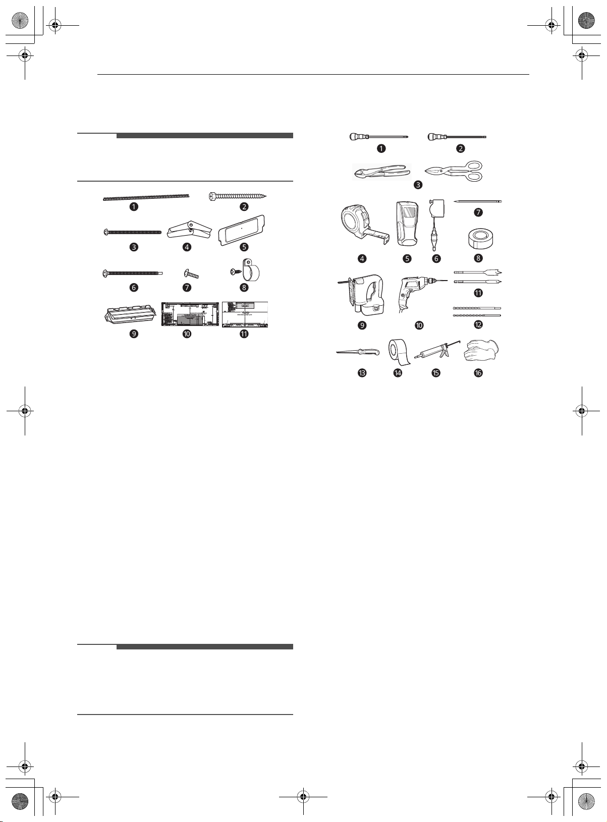
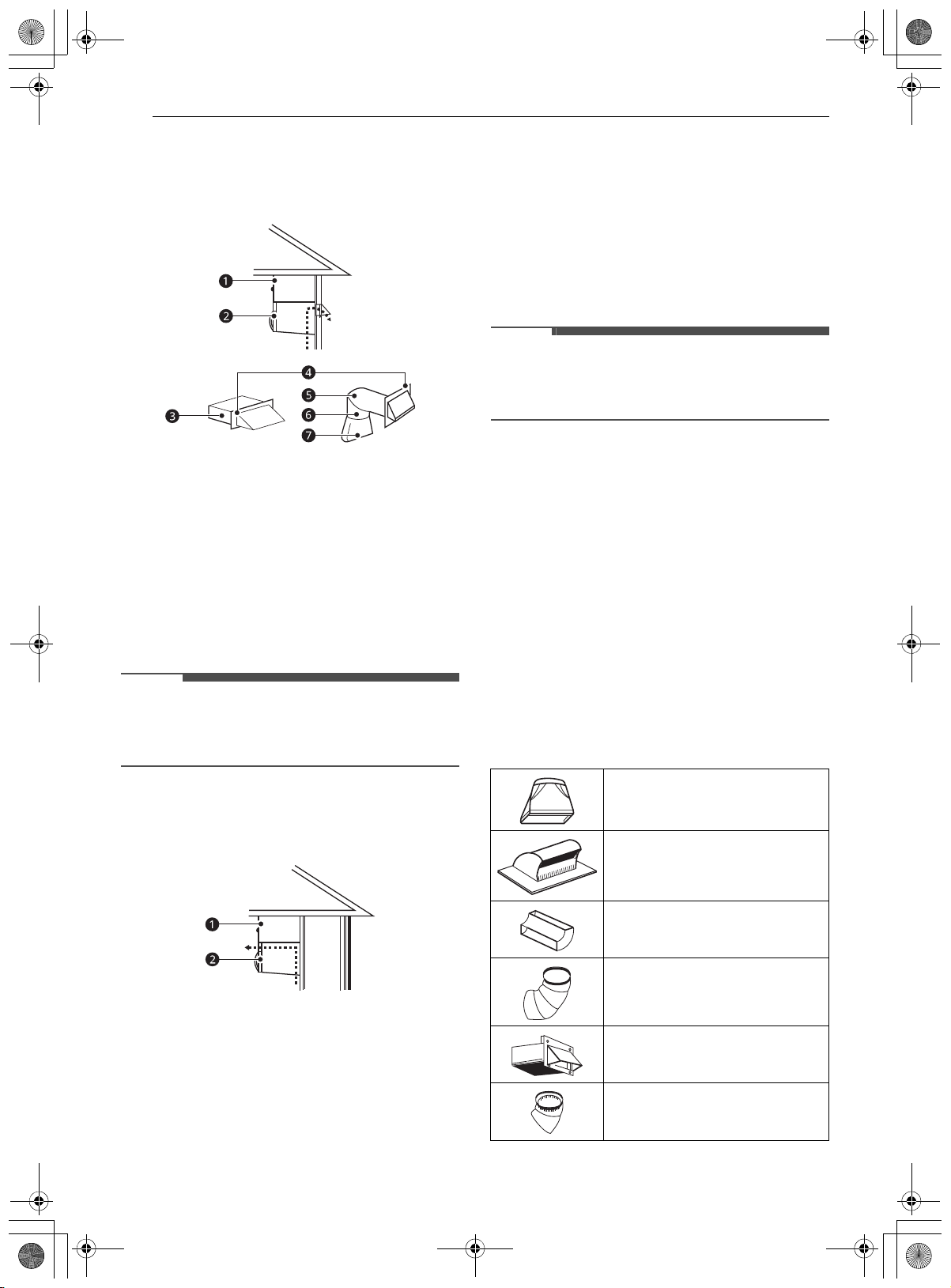
model number plate ais located on the oven
front.
The mounting plate bis located in the upper
packing material.
NOTE
• Vent grille appearance varies by model.
Make sure you have enough space and support.
• Mount the oven against a flat, vertical wall, so it
is supported by the wall. The wall should be
constructed of minimum 2" x 4" wood studding
and 3/8" thick drywall or plaster/lath.
• Attach the two lag screws supporting the oven to
a vertical, 2" x 4" wall stud.
• Do not mount the microwave oven to an island
or peninsula cabinet.
• Be sure the upper cabinet and rear wall
structures can support 150 lbs., plus the weight
of any items you place inside the oven or upper
cabinet.
• Locate the oven away from areas with strong
drafts, such as windows, doors, and strong
heating vents.
• The microwave oven has an inset handle on the
right side. To access the handle and allow the
door to swing open, install the product with
sufficient clearance on the sides. Do not block
the right side handle area by installing it against
a wall or cabinet.
(Model: MVEL213**, MVEL203**)
• Be sure you have enough space (minimum
vertical and horizontal clearance).
aMaximum 13": cabinet depth
bMinimum 30": cabinet opening width
cMinimum 30": clearance from bottom of
cabinet to cooking surface or countertop
before installation. (Use templates included
with installation instructions.)
dGrounded Outlet (inside upper cabinet)
ePower Supply Cord Hole
fMinimum 2": clearance from the top of the
range control panel to the bottom of
microwave oven (slide-out hood model)
WARNING
• If you do not mount the oven as instructed, you
risk personal injury and/or property damage.
• If your range has cooktop controls in the front,
unplug the range before covering the cooktop to
prevent risk of fire and damage if the knobs are
accidentally activated while installing the OTR.
• The product is heavy. Use at least 2 people when
lifting or installing the appliance to avoid injury
or product damage.
CAUTION
• Before you begin installing the oven, place a
piece of the carton or other heavy material (a
blanket) over the countertop or cooktop to
protect it. Do not use a plastic cover. Failure to
protect these surfaces could result in property
damage.
or
us_main.book.book Page 5 Tuesday, May 3, 2022 8:07 AM

6INSTALLATION
Parts
Included Parts
NOTE
• Depending on your ventilation requirements,
you may not use all of these parts.
aPower cord clamp bushing (1ea): for the cord
hole in a metal upper cabinet
b1/4" x 2" lag screw (2ea): for wall stud holes
c1/4" x 3" toggle bolts (2ea): for drywall holes
dSpring toggle heads (2ea): for the toggle bolts
eCover plate (1ea): for room venting installation
f1/4" x 3" bolts (2ea): for securing to the upper
cabinet
gTapping screws (3ea): for attaching the damper
duct connector
hPower cord clamp (1ea) and dark-colored
mounting screw (1ea): to hold the power cord
iBack-draft damper: 2 pieces must be
assembled as shown. (for roof venting or wall
venting installation, not for room venting
installation)
jUpper cabinet template (1ea)
kRear wall template (1ea)
NOTE
• You need to install at least two lag screws into a
2" x 4" stud and four anchor bolts into the wall.
The mounting area must meet the 150 lb. weight
requirement.
Tools and Materials
You will need the following tools and materials for
the installation:
aPhillips screwdriver (for the screws)
bFlat blade screwdriver (for the toggle bolts)
cSmall side cutters (nipper) or tin snips
dMeasuring tape (metal preferred)
eStud finder
fPlumb line
gPencil
hClear tape (for taping the templates to the wall)
iSaber saw (for cutting vent holes for roof or
wall venting)
jElectric drill
k3/8" and 3/4" wood drill bits
l1/2" and 3/16" drill bits
mKeyhole saw (for the power cord hole)
nDuct tape
oCaulking gun and caulk
pGloves
us_main.book.book Page 6 Tuesday, May 3, 2022 8:07 AM

7INSTALLATION
ENGLISH
NOTE
• If you have brick or masonry walls, you will need
special hardware and tools.
• The ductwork you need for the installation is not
included. All wall and roof caps must have a
back-draft damper (shown in Parts section).
• Wear proper gloves to protect your hands from
injury.
Installing the Microwave
Oven
Step 1: Prepare the Electrical
Connection
1 Locate the grounded electrical outlet bfor
this oven in the upper cabinet a.
NOTE
• The outlet should be on a circuit dedicated to the
microwave oven (120V, 60 Hz., AC only) with a 15
or 20 A fused electrical supply.
• Important: If you do not have the proper wall
outlet, you MUST have one installed by a
qualified electrician.
2 You will cut the hole cfor the power supply
cord later when you prepare the wall and
upper cabinet in Step 4.
NOTE
• Do not use an extension cord. Keep the power
cord dry and do not pinch or crush it.
WARNING
• Avoid electric shock. This appliance must be
grounded.
• Improper grounding could result in electric
shock or other personal injury.
Do not, under any circumstances, remove the
power supply cord grounding prong.
Step 2: Prepare the Venting System
WARNING
• This oven must be properly vented.
You may vent your ductwork in one of three ways.
Do not vent into a wall cavity, an attic, or an
unused area.
Roof Venting
The oven is located on an outside wall near the
roof: 3 1/4" x 10" duct dor minimum 6" diameter
round duct e.
aCabinet
bOven
cRoof Cap
d3 1/4" x 10" duct
eMinimum 6" diameter round duct
f3 1/4" x 10" to 6" round duct transition
us_main.book.book Page 7 Tuesday, May 3, 2022 8:07 AM

8INSTALLATION
Wall Venting
The oven is located on an outside wall of your
house: 3 1/4" x 10" duct cor minimum 6"
diameter round duct f.
aCabinet
bOven
c3 1/4" x 10" duct
dWall cap
eElbow
fMinimum 6" diameter round duct
g3 1/4" x 10" to 6" round duct transition
NOTE
• If you choose the rear exhaust method (roof
venting or wall venting), be sure there is enough
clearance within the wall for the exhaust duct.
Room Venting
The oven is located on an inside wall of your
house.
aCabinet
bOven
When Installing Venting
• Keep the length of the ductwork and the number
of elbows to a minimum to ventilate your oven
efficiently. See examples in next section.
• Keep the size of the ductwork the same.
• Do not install two elbows together.
• Use duct tape to seal all joints in the duct system.
• Use caulking to seal the exterior wall or roof
opening around the cap.
• After installation, check the outside hood
opening and operation.
• For the outside hood opening and size refer to
the upper cabinet template or rear wall
template.
NOTE
• The ductwork you need for outside ventilation is
not included with your oven. See the standard
ductwork fittings.
Standard Ductwork Fittings
If the existing duct is round, you must use a
rectangular-to-round adapter, with a rectangular
3" extension duct installed between the damper
assembly and the adapter to prevent the exhaust
damper from sticking.
Duct Length
The total length of the duct system, including
straight duct, elbows, transitions, and wall or roof
caps must not exceed 140 feet.
For best performance, do not use more than three
90 degree elbows, and keep the length as short as
possible.
Below are the standard fittings and their
equivalent length in feet.
3 1/4" x 10" to 6" transition = 5 ft
3 1/4" x 10" roof cap = 24 ft
3 1/4" x 10" 90° elbow = 25 ft
90° elbow = 10 ft
3 1/4" x 10" wall cap = 40 ft
45° elbow = 5 ft
us_main.book.book Page 8 Tuesday, May 3, 2022 8:07 AM

9INSTALLATION
ENGLISH
To calculate the equivalent length of each duct
piece used, see the examples below.
Step 3: Prepare the Venting Blower
Your microwave oven is shipped with the blower
assembled for roof venting. You need to adjust the
blower if you want wall-venting or room-venting
installation.
WARNING
• Electric shock hazard! Unplug unit before
working on it.
• Do not pull or stretch the blower wiring. Pulling
and stretching the blower wiring could result in
electric shock.
• To avoid risk of property damage, unplug the
microwave oven or disconnect the power at the
source by removing the fuse or throwing the
circuit breaker.
• To avoid risk of personal injury, wear protective
gloves when handling the mounting plate.
Installation
1 Remove any shipping materials and parts
from inside the microwave oven. Set them
aside for later use.
2 Cover the countertop or cooktop with a thick,
protective covering to protect it from damage
and dirt. If your range has cooktop controls in
the front, unplug the range before covering
the cooktop to prevent risk of fire and
damage if the knobs are accidentally activated
while installing the OTR.
aBlanket, cardboard or other covering
NOTE
• If you have a free-standing range, disconnect it,
move it onto a piece of cardboard or hardboard
and pull it away from the wall, so that you can
get closer to the upper cabinet and back wall for
easier measuring and drilling.
3 Locate the exhaust adapter, grease filters and
hardware packet.
4 At this point, remove any adhesive tape (if
there is any), on the exhaust adapter, the
grease filters and the power supply cord.
Roof-Venting Installation
This oven is shipped assembled for roof-venting.
1 Insert the tabs on each side of the damper
into the holes at the inside rear of the
adapter. Attach the exhaust adapter ato the
blower plate bwith the two tapping screws
provided. Make sure that the damper c
swings freely.
3 1/4" x 10" flat elbow = 10 ft
For 3 1/4" x 10" systems
1/4" x 10" 90° elbow a(1ea)
Wall cap b(1ea)
Straight duct (8 ft)
Total length
= 25 ft
= 40 ft
= 8 ft
= 73 ft
For 6" round systems
Transition (1ea)
90°elbows b(2ea)
Wall cap c(1ea)
Straight duct (8 ft)
Total length
= 5 ft
= 20 ft
= 40 ft
= 8 ft
= 73 ft
6 ft
2 ft
2 ft
6 ft
us_main.book.book Page 9 Tuesday, May 3, 2022 8:07 AM

10 INSTALLATION
Wall-Venting Installation
1 Remove one or several blower plate mounting
screw(s) aand the blower plate b. Remove
the cover plate cand one or two blower unit
mounting screw(s) g.
dBlower unit
eKnockouts
fBack plate
2 Carefully lift the blower unit out of the
microwave oven.
3 Use side cutters or tin snips to cut out and
remove the knockouts bfrom the back plate
a. Be careful not to distort the back plate.
Discard the knockouts.
4 To avoid pinching the blower wire, make sure
that it is channeled underneath and between
the two exhaust ports when they are rotated.
5 Rotate and reinstall the blower unit aso that
the exhaust ports bface the rear of the
cabinet and are aligned with the rear
knockouts. When you insert the blower unit,
the blower wire cmust be routed as shown.
6 Attach the blower plate dto the microwave
oven so the blower unit exhaust ports cand
blower plate opening are aligned. Attach one
or two blower unit mounting screw(s) fand
then one or several blower plate mounting
screw(s) a. Attach the cover plate gon the
blower plate with a screw h.
bBlower unit
eBack plate
7 Insert the tabs on each side of the damper
into the holes at the inside rear of the
adapter. Attach the exhaust adapter ato the
back plate wall side. Push in securely until it is
past the top locking tabs cand in the lower
locking tabs c. Make sure that the damper
hinge is at the top and that the damper
swings freely.
us_main.book.book Page 10 Tuesday, May 3, 2022 8:07 AM

11INSTALLATION
ENGLISH
bDamper (hinge side up)
cGuides
eSlide exhaust adapter into guides on rear
panel.
Room-Venting Installation
1 Follow steps 1 and 2 under Wall-Venting
Installation.
2 Rotate and reinstall the blower unit aso that
the exhaust ports bface the front of the
cabinet. When you insert the blower unit, the
blower wire cmust be routed as shown.
3 Attach one or two blower unit mounting
screw(s) a. Attach the cover plate bon the
back. Attach the blower plate cto the
microwave oven. Attach one or several blower
plate mounting screw(s) d. Attach the cover
plate bon the blower plate and attach the
screw g
eBlower unit
fBack plate
WARNING
• Fire hazard! Correctly install the vent fan before
use.
When changing the vent fan position for wall
venting or room venting:
• Properly align the ventilation fan openings and
blower plate knockouts.
• Ventilation fan openings should be completely
exposed to the outside.
• After installation, check the air ventilation path.
Refer to step 2 for proper vent selection.
Improper installation can cause problems such as:
• Inability to assemble the blower plate or
ventilation motor correctly
• Abnormal noise during product operation
• Weak ventilation
• Product overheating and the possibility of
product breakdown or fire
Step 4: Prepare the Wall and Upper
Cabinet
WARNING
• To avoid personal injury or property damage, do
not attempt to install this microwave oven if you
cannot find a wall stud. Consult a carpenter or
contractor.
Measure and Attach Templates
1 Using a plumb line and (metal) measuring
tape, find and mark the vertical center line on
the back wall of the opening.
2 Find and mark one or two points where the
studs are on the wall. (Studs are normally 16
us_main.book.book Page 11 Tuesday, May 3, 2022 8:07 AM

12 INSTALLATION
inches apart.) Then measure and mark the
stud locations. If you cannot find any wall
studs, consult a local building contractor.
3 Draw a vertical line on the wall at the center of
the 30″wide opening.
NOTE
• Be sure the minimum width is 30 inches.
4 Center the rear wall template bin the space
by lining up the plumb line on the wall with
the centerline on the template. Then securely
tape or tack the rear wall template in place.
Make sure the minimum width is 30 inches
and that the top of the rear wall template is
located a minimum of 30 inches above the
cooking surface.
Measure the bottom of the upper cabinet
frame. Trim edges A, B, and C on the upper
cabinet template aso that the template will
fit on the bottom of the upper cabinet. If the
upper cabinet has a recessed frame, trim the
template so it fits inside the recessed area. If
needed, the template can be trimmed inside
the printed trim lines, as long as you are able
to align the centerline correctly. Align the
centerline of the upper cabinet template with
the centerline of the rear wall template, then
securely tape or tack the upper cabinet
template in place.
WARNING
• To avoid risk of personal injury, electric shock or
death:
- Note where electrical outlets and electrical
wires are before you drill into the wall.
- Locate and disconnect power to any electrical
circuits that could be affected by installing this
oven.
• To avoid risk of personal injury, electric shock or
death, cover the edge of the power supply cord
hole with the power supply cord bushing.
Drill Holes in Wall and Cabinet
1 Drill holes on the circles. If there is a stud, drill
a 3/16" hole for lag screws. If there is no stud,
drill a 3/4" hole for toggle bolts. Make sure to
use at least 1 lag screw in a stud, and 2 toggle
screws in the drywall or the plaster.
2 Drill a 3/8” hole at points J and K on the upper
cabinet template.
If the bottom of the upper cabinet is recessed
3/4" or more, you will need 2"x 2" filler blocks
b(not included) to provide additional support
for the bolts.
aCabinet front
cCabinet bottom shelf
Mark the center of each filler block and drill a
3/8” diameter hole at the marks.
Align filler blocks bover the two openings in
the top of the microwave oven cabinet and
attach to the cabinet with masking tape.
3 Cut or drill a 2" diameter hole at the area
marked "M power supply cord hole" on the
upper cabinet template. If the upper cabinet
is metal, you will need to cover the edge of the
hole with the power supply cord bushing
(supplied) to prevent damage to the cord
from the rough metal edge.
4 Cut out the venting areas (with the saber saw)
• Roof-venting: cut out the shaded area
marked L on the upper cabinet template.
• Wall-venting: cut out the shaded area
marked F on the rear wall template.
• Room-venting: go to Step 5: Install the
Mounting Plate.
us_main.book.book Page 12 Tuesday, May 3, 2022 8:07 AM

13INSTALLATION
ENGLISH
5 Complete whichever venting system you have
chosen. Use caulking compound to seal the
exterior wall or roof opening around the wall
cap or roof cap.
Step 5: Install the Mounting Plate
The oven must be connected to at least one wall
stud.
1 Center the rear wall template in the space by
lining up the plumb line on the wall with the
centerline on the template. Then securely
tape or tack the rear wall template in place.
Make sure the minimum width is 30 inches
and that the top of the rear wall template is
located a minimum of 30 inches above the
cooking surface.
NOTE
• If the cabinets are not plumb, adjust the rear
wall template to the cabinets. If the front edge of
the cabinet is lower than the back edge, adjust
the template to be level with the cabinet front.
2 Drill holes at points A and B. Drill the third
hole inside area C, through one of the bottom
holes to match the location of a stud. If there
is a stud, drill a 3/16 hole for lag screws. If
there is no stud, drill a 5/8 hole for toggle
bolts. These holes must be used for
mounting. If the holes are not used, the
installation will not be secure. The installer
must use these holes for proper installation.
Use toggle bolts through these holes, unless
one of them lines up with a stud. Use a lag
screw for studs. Make sure to use at least 1
lag screw in a stud, and 2 toggle bolts in the
drywall or the plaster.
aMinimum 66" from the floor
bFor wall - venting only
cDraw lines on studs
dDraw center Line
eMounting plate
fSupport tab
NOTE
• Cut out the shaded area marked F on the rear
wall template for wall-venting.
3 Remove the template from the rear wall.
4 Attach the plate to the wall e. To use spring
toggle head bolts d: Remove the toggle
wings cfrom the bolts. Insert the bolts into
the mounting plate aand replace the spring
toggle head to 3/4 of the length past the bolt
ends. Insert the spring toggle head into the
holes in the wall to mount the plate. You may
pull forward on the plate to help in tightening
the toggle bolts. Tighten all bolts.
bSpace more than wall thickness
fBolt end
Step 6: Attach the Oven to the Wall
WARNING
• To avoid risk of personal injury or property
damage, you will need two people to install this
microwave oven.
NOTE
• Do not apply force directly to the outside bottom
surface of the product. The slide-out vent latch
may be damaged if force is applied directly to
the center bottom of the product.
• Set the product down on a flat surface only
during unpacking, gently set the product onto a
flat surface such as a kitchen table or counter.
• Do not lift or support the product by the bottom
center face. The product is best handled by the
bottom sides near the legs.
A
AB
B
C
us_main.book.book Page 13 Tuesday, May 3, 2022 8:07 AM

14 INSTALLATION
NOTE
• Do not remove the packing tape on the slide-out
vent during installation. Once the product is fully
installed, remove the tape and check that the
vent easily slides open and closed with a push.
1 Carefully lift the microwave oven and hang it
on the support tabs at the bottom of the
mounting plate. Reaching through the upper
cabinet, thread the power supply cord a
through the power supply cord hole bin the
bottom of the upper cabinet.
2 Rotate the microwave oven upward so the top
of the oven is against the bottom of the upper
cabinet or cabinet frame.
3 Then insert a bolt down through each hole a
in the upper cabinet bottom. Tighten the bolts
until the gap between the upper cabinet and
microwave oven is closed.
4 Roof venting installation: Install the ductwork
through the vent opening in the upper
cabinet. Use a caulking gun to seal the
exterior roof opening around the exhaust cap.
aDamper
5 Use the power supply cord clamp bto bundle
the power supply cord. Install the power
supply cord clamp to the inside of the cabinet
using a screw.
aDuct
6 Grasp the filter screen with one hand holding
the ring and the other hand holding the
opposite end. Insert the end of the filter
screen without the ring into the opening and
slide towards the side of the microwave oven.
Insert the ring end of the filter screen into the
opening and slide the entire screen towards
the center of the microwave until the screen is
securely in position. Repeat for the other filter
screen.
1
2
3
1
2
us_main.book.book Page 14 Tuesday, May 3, 2022 8:07 AM

15APPENDIX
ENGLISH
APPENDIX
Checking Operation
Before Using the Oven
1 Plug in the power supply cord.
2 Read your Owner’s Manual, and then check
the operation of your oven.
us_main.book.book Page 15 Tuesday, May 3, 2022 8:07 AM

16 Memo
us_main.book.book Page 16 Tuesday, May 3, 2022 8:07 AM

MANUEL D’INSTALLATION
FOUR À MICRO-ONDES
Veuillez lire attentivement le présent manuel d’installation avant
d’installer lʼappareil et conservez-le à portée de la main pour le
consulter en tout temps.
FRANÇAIS
MVEL213** MVEL212** MVEL203**
www.lg.com
Copyright © 2022 LG Electronics Inc. Tous droits réservés
fc_main.book.book Page 1 Wednesday, May 4, 2022 3:37 PM

TABLE DES MATIÈRES
2
3 IMPORTANTES INSTRUCTIONS
DE SÉCURITÉ
3 LISEZ TOUTES LES CONSIGNES AVANT
LʼUTILISATION
3 AVERTISSEMENT
5 INSTALLATION
5 Avant l’installation
7 Installation du four à micro-ondes
16 ANNEXE
16 Vérification du fonctionnement
fc_main.book.book Page 2 Wednesday, May 4, 2022 3:37 PM

3IMPORTANTES INSTRUCTIONS DE SÉCURITÉ
FRANÇAIS
IMPORTANTES INSTRUCTIONS DE SÉCURITÉ
LISEZ TOUTES LES CONSIGNES AVANT LʼUTILISATION
Messages de sécurité
Il est très important dʼassurer votre sécurité et celle des autres.
Nous fournissons de nombreux conseils de sécurité importants dans ce manuel et sur votre appareil. Lisez
toujours l’ensemble des messages de sécurité et respectez-les.
AVERTISSEMENT
AVERTISSEMENT
• Pour réduire les risques dʼexplosion, dʼincendie, de mort, de décharge électrique, de brûlure ou de
blessures lors de lʼutilisation de lʼappareil, prenez les précautions élémentaires, y compris les suivantes :
Installation
• Cet appareil doit être installé uniquement par du personnel d’entretien qualifié.
• Vous aurez besoin de deux personnes pour installer cet appareil. Il est lourd et pourrait causer des
blessures s’il n’est pas manipulé correctement.
• Évitez toute décharge électrique.
Avant de percer le mur, notez l’emplacement des prises électriques et des fils électriques qui pourraient
être dissimulés derrière le mur. Vous risquez de recevoir une décharge électrique si la mèche de votre
perceuse entre en contact avec des fils électriques.
Repérez les circuits électriques qui pourraient être affectés par l’installation de cet appareil et coupez
leur alimentation. Si vous ne coupez pas le courant, vous risquez de recevoir une décharge électrique.
• Cet appareil doit être mis à la terre.
En cas de court-circuit électrique, la mise à la terre réduit le risque de décharge électrique, car elle
permet au courant électrique de retourner à la terre. Cet appareil est équipé d’un cordon qui comprend
un fil de mise à la terre et une fiche de mise à la terre.
Ceci est le symbole d’alerte de sécurité.
Ce symbole vous alerte de dangers potentiels qui peuvent causer la mort ou des blessures. Tous
les messages de sécurité seront précédés du symbole d’alerte de sécurité et du terme
AVERTISSEMENT ou MISE EN GARDE.
Ces mots signifient :
AVERTISSEMENT
Vous pouvez être tué ou gravement blessé si vous ne suivez pas les consignes.
MISE EN GARDE
Vous pourriez vous blesser ou endommager le produit si vous ne suivez pas les consignes.
Tous les messages de sécurité vous avertissent d’un danger potentiel et vous disent comment réduire le
risque de blessure, ainsi que ce qui peut arriver si les instructions ne sont pas suivies.
fc_main.book.book Page 3 Wednesday, May 4, 2022 3:37 PM

4IMPORTANTES INSTRUCTIONS DE SÉCURITÉ
GARDEZ CES CONSIGNES
• Insérez la fiche dans une prise de courant correctement installée et mise à la terre.
aFiche (de mise à la terre) à trois broches
bPrise de courant correctement polarisée et mise à la terre
• N’utilisez pas de rallonge.
• Gardez le cordon d’alimentation au sec et évitez de le pincer ou de l’écraser. Le non-respect de cette
consigne peut entraîner un risque d’incendie.
• Ne retirez en aucun cas la broche de mise à la terre du cordon d’alimentation.
• Une utilisation inadéquate de la fiche de mise à la terre peut causer une décharge électrique et/ou un
incendie.
Si vous n’êtes pas sûr que le four est correctement mis à la terre, ou si vous ne comprenez pas bien les
instructions de mise à la terre, consultez un électricien qualifié.
• N’utilisez pas de fusible dans le circuit neutre ou de mise à la terre.
• Une mise à la terre incorrecte pourrait provoquer une décharge électrique, un incendie ou d’autres
blessures.
Fonctionnement
• Si vous ne respectez pas les instructions d’utilisation du four à micro-ondes, vous risquez d’être exposé à
une trop grande quantité d’énergie micro-ondes.
• N’essayez pas de faire fonctionner le four à micro-ondes avec la porte ouverte.
• N’essayez pas de modifier ou d’annuler les verrouillages de sécurité.
• Ne placez pas d’objets entre la façade du four à micro-ondes et la porte.
• Ne laissez pas de la saleté ni de résidus de nettoyant s’accumuler sur les surfaces plates autour de la
porte du four à micro-ondes.
• Ne faites pas fonctionner le four à micro-ondes s’il est endommagé.
• La porte du four à micro-ondes doit être fermée correctement pour que celui-ci fonctionne de façon
sécuritaire.
• N’utilisez pas le four à micro-ondes si :
- la porte est déformée.
- les charnières ou les loquets sont cassés ou desserrés.
- les joints de la porte, les surfaces d’étanchéité ou le verre sont cassés.
• N’essayez pas de régler ou de réparer le four vous-même. Il faut le faire régler et réparer par un
technicien qualifié, qui pourra vérifier qu’il n’y a pas de fuite de micro-ondes après avoir réparé le four.
fc_main.book.book Page 4 Wednesday, May 4, 2022 3:37 PM
Other manuals for MVEL213 Series
3
This manual suits for next models
2
Table of contents
Languages:
Other LG Microwave Oven manuals