LG FPD2200 User manual

SOURCE MENU DOWN/UP VOLUME POWER
SET
COLOR MONITOR
SERVICE MANUAL
CAUTION
BEFORE SERVICING THE UNIT,
READ THE SAFETY PRECAUTIONS IN THIS MANUAL.
CHASSIS NO. : CL-16
FACTORY MODEL: LM295B
MODEL: FPD2200

1. LCD CHARACTERISTICS
Type : TFT Color LCD Module
Active Display Area : 22.0 inches (56cm)
Size : 542.0(W) x 375.0(H) x 35.3(T)
Pixel Pitch : 0.294mm (H) x 0.294mm (V)
Color Depth : 8-bit, 16,777,216 colors
Surface Treatment : Anti-Glare, Hard Coating (3H)
Backlight Unit : 4CCFL (Cold Cathode
Fluorescent Lamp)
2. OPTICAL CHARACTERISTICS
2-1. Viewing Angle by Contrast Ratio
≥
10
Left : 70° typ. Right : 70° typ.
Top : 70° typ. Bottom : 70° typ.
2-2. Luminance : 180 cd/m2typ.
2-3. Angle at Half Luminance
Left : 45° min. Right : 45° min.
Top : 35° min. Bottom : 35° min.
2-4. Contrast Ratio : 300° typ.
3. SIGNAL (Refer to the Timing Chart)
3-1. Video Input
1) Signal Input :
15 pin D-Sub Connector/
DVI-D Connector
2) Input From : Separate, RGB Analog, 0.7Vp-p/
75Ω, Positive Digital
3) Resolution (max.): Analog - 1600x1024@60Hz
Digital - 1600x1024@60Hz
3-3. Sync Input
Horizontal : 30 ~ 70 kHz
Vertical : 56 ~ 61 Hz
Input Form : Separate, Analog, Digital
4. POWER SUPPLY
4-1. Power Adaptor
Input : AC 100~240V, 47 or 63Hz
Output : DC 15V 5.0A
4-2. Power Consumption
5. ENVIRONMENT
5-1. Operating Temperature: 10°C~35°C (50°F~95°F)
(Ambient)
5-2. Relative Humidity : 10%~80%
(Non-condensing)
6. DIMENSIONS (with TILT/SWIVEL)
Width : 582 mm (22.91'')
Depth : 73 mm (7.19'')
Height : 467.5 mm (2.87'')
7. WEIGHT (with TILT/SWIVEL)
Net. Weight : 14.8 kg (32.63 lbs)
Gross Weight : 18.0 kg (39.69 lbs)
8. USB
Upstream : 1 port, Downstream : 2 port
Speed : High-12Mbps, Low-1.5Mbps
CONTENTS
SPECIFICATIONS
- 2 -
SPECIFICATIONS ................................................... 2
PRECAUTIONS ....................................................... 3
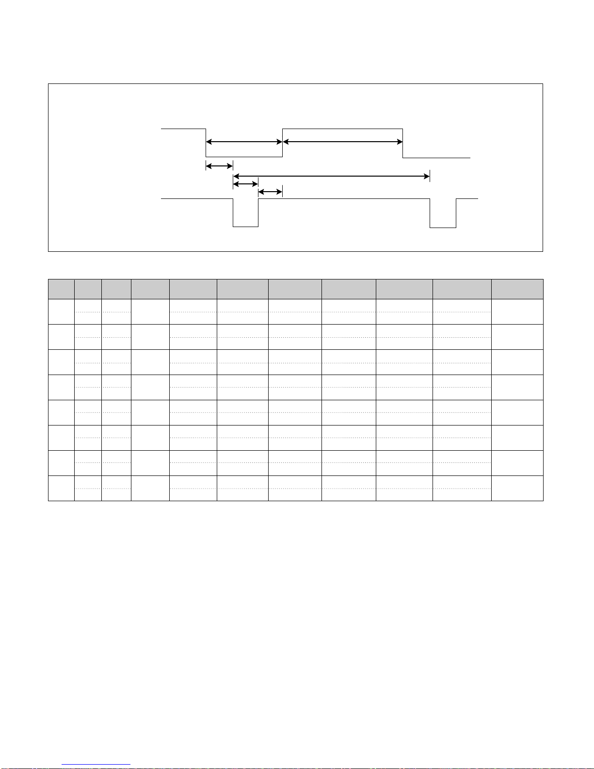
TIMING CHART ....................................................... 4
OPERATING INSTRUCTIONS ................................ 5
WIRING DIAGRAM ............................................... 10
DISASSEMBLY .......................................................11
BLOCK DIAGRAM ................................................ 14
DESCRIPTION OF BLOCK DIAGRAM...................15
ADJUSTMENT ...................................................... 16
TROUBLESHOOTING GUIDE .............................. 17
PRINTED CIRCUIT BOARD................................... 21
EXPLODED VIEW...................................................24
REPLACEMENT PARTS LIST ...............................26
SCHEMATIC DIAGRAM......................................... 34
MODE
POWER ON (NORMAL)
STAND-BY
SUSPEND
POWER OFF
H/V SYNC
ON/ON
OFF/ON
ON/OFF
-
POWER CONSUMPTION
less than 80 W
less than 8 W
less than 8 W
less than 8 W
LED COLOR
GREEN
AMBER
AMBER
OFF
VIDEO
ACTIVE
OFF
OFF
-

- 3 -
WARNING FOR THE SAFETY-RELATED COMPONENT.
• There are some special components used in LCD
monitor that are important for safety. These parts are
marked on the schematic diagram and the
replacement parts list. It is essential that these critical
parts should be replaced with the manufacturer’s
specified parts to prevent electric shock, fire or other
hazard.
• Do not modify original design without obtaining written
permission from manufacture or you will void the
original parts and labor guarantee.
TAKE CARE DURING HANDLING THE LCD MODULE
WITH BACKLIGHT UNIT.
• Must mount the module using mounting holes arranged
in four corners.
• Do not press on the panel, edge of the frame strongly
or electric shock as this will result in damage to the
screen.
• Do not scratch or press on the panel with any sharp
objects, such as pencil or pen as this may result in
damage to the panel.
• Protect the module from the ESD as it may damage the
electronic circuit (C-MOS).
• Make certain that treatment person’s body are
grounded through wrist band.
• Do not leave the module in high temperature and in
areas of high humidity for a long time.
• The module not be exposed to the direct sunlight.
• Avoid contact with water as it may a short circuit within
the module.
• If the surface of panel become dirty, please wipe it off
with a softmaterial. (Cleaning with a dirty or rough cloth
may damage the panel.)
WARNING
BE CAREFUL ELECTRIC SHOCK !
• If you want to replace with the new backlight (CCFL) or
inverter circuit, must disconnect the AC adapter
because high voltage appears at inverter circuit about
650Vrms.
• Handle with care wires or connectors of the inverter
circuit. If the wires are pressed cause short and may
burn or take fire.
PRECAUTION
CAUTION
Please use only a plastic screwdriver to protect yourself
from shock hazard during service operation.

TIMING CHART
- 4 -
VIDEO
SYNC
B
D
CFE
A
Mode H/V
Sort
1
2
3
4
5
6
7
8
<< Dot Clock (MHz), Horizontal Frequency (kHz), Vertical Frequency (Hz), Horizontal etc... (µs), Vertical etc... (ms) >>
Sync
Polarity
Frequency
DOT
Clock
Total Period
(E) Video Active
Time (A) Sync Duration
(D) Back Porch
(F)
Front Porch
(C) Resolution
H–31.469 800 640 16 96 48
V–59.94 525 480 10 2 33
H + 35.156 1024 800 24 72 128
V + 56.250 625 600 1 2 22
H–48.363 1344 1024 24 136 160
V–60.0 806 768 3 6 29
H + 37.879 1056 800 40 128 88
V + 60.317 628 600 1 4 23
H 64.35 2160 1600 64 192 304
V + 59.92 1074 1024 1 3 46
H + 60.000 1800 1280 96 112 312
V + 60.000 1000 960 1 3 36
H + 63.981 1688 1280 48 112 248
V + 60.02 1066 1024 1 3 38
800x600
60Hz
800x600
56Hz
640x480
60Hz
1024x768
60Hz
1600x1024
60Hz
1280x960
60Hz
1280x1024
60Hz
H + 75 2160 1600 64 192 304
V + 60.00 1250 1200 1 3 46 1600x1200
60Hz
25.175
36.0
40.0
65.0
108.0
108.0
139.0
162.0

SOURCE MENU DOWN/UP VOLUME POWER
SET
OPERATING INSTRUCTIONS
- 5 -
FRONT VIEW
FRONT PANEL CONTROLS
SOURCE MENU DOWN/UP LEFT/RIGHT SET
Use this button to enter or exit the On Screen Display.
This indicator lights up green when the monitor operates normally.
If the monitor is in DPM (Energy Saving) mode (stand-by/ suspend/power off),
this indicator color changes to amber.
Power Indicator
Use this button to turn the monitor on or off.
Power Button
Use this button to enter a selection in the On Screen Display.
Power Button
MENU Button
Power Indicator
SOURCE Selection
Button
SET Button
DOWN/UP ( )
Buttons LEFT/RIGHT ( )
Buttons
MENU Button
Use these buttons to choose or adjust items in the On Screen Display.
DOWN/UP ( )
Buttons
Use these buttons to choose or adjust items in the On Screen Display.
LEFT/RIGHT ( )
Buttons
SET Button
Use this button to select an input signal.
DSUB
DVI
V2
V1
INPUT SELECT
DIGITAL
ANALOG
(S)
(AV)
SOURCE
MENU
DOWN/UP
LEFT/RIGHT
SET
SOURCE DOWN/UP SET
SOURCE Selection
Button •DVI DIGITAL : DVI digital signal
•DSUB ANALOG : 15-pin D-sub
analog signal
•V1(AV): Composite video
•V2(S): S video

- 6 -
REAR PANEL CONTROLS
DC15V S-Video Video
IN PC Audio
IN
Sound
L R Audio
L R
D
Connected to another object
(stand type and wall-mounted
type –optional)
Locking slot
connected to a locking cable that
can be purchased separately at
most computer stores.
DC15V S-Video Video
IN
D
DC Power Connector
DVI-D Connector S-Video Input Jack
D-sub Connector Composite Video
Input Jack

Making adjustments to the image size, position and
operating parameters of the monitor are quick and easy
with the On Screen Display Control system. A quick
example is given below to familiarize you with the use of
the controls. Following section is an outline of the
available adjustments and selections you can make using
the OSD.
To make adjustments in the On Screen Display, follow
these steps:
1.
Press the MENU Button, the main menu of the OSD
will appear.
2.
To access a control, use the DOWN/UP ( )
Buttons. When the desired control icon is highlighted,
press the SET Button.
3.
Press the DOWN/UP ( ) Buttons to select the
desired item.
4.
Use the VOLUME ( ) Buttons to adjust the item
to the desired level.
5.
Accept the changes by pressing the SET Button.
6.
Exit the OSD by Pressing the MENU Button.
VOLUME
MENU
MENU
DOWN/UP SET
SET DOWN/UP
NOTE
Allow the monitor to stabilize for at least 30 minutes
before making image adjustment.
- 7 -
Listed below are the icons, icon names, and icon
descriptions of the items that are shown on the Menu.
Adjusting the Screen when Using a Computer
Brightness
Used to adjust the brightness of the screen.
Contrast
Adjust the display to the contrast desired.
USER
9300K
6500K
RED / GREEN / BLUE
To set your own color levels.
To appear the displays color temperature.
•9300K:Slightly bluish white.
•6500K:Slightly reddish white.
Vertical Position
To move image up and down.
Horizontal Position
To move picture image left and right.
Note : When a digital signal is set as an input, only the
SETUP item can be adjusted. You do not need to adjust
the other items.
Image
RGB
Color
Position
Setup
PIP
CONTRAST/BRIGHTNESS
CONTRAST
BRIGHTNESS 100
100
Tracking
Position
Setup
PIP
Tracking
Image
RGB
Color
COLOR ADJUSTMENT
USER 9300K 6500K
50RED
50GREEN
60BLUE
RGB
Color
Setup
PIP
Tracking
IMAGE POSITION
VERTICAL
HORIZONTAL 50
50
Image
Position

- 8 -
To minimize any vertical bars or stripes visible on
the screen background.The horizontal screen size
will also change.
To adjust the focus of the display. This item allows
you to remove any horizontal noise and clear or
sharpen the image of characters.
Phase adjustment should be done after adjusting
the Clock.
To choose the language in which the control
names are displayed.
This function displays the image in its original
size or enlarged size so as to fit in the full screen
of the LCD panel.
To adjust position of the OSD window on the
screen. Press the SET button to display the
submenu for OSD POSITION.
LANGUAGE
IMAGE SIZE
OSD POSITION
To select beep on or off.
To adjust horizontal and vertical image size
simultaneously.
If you want to move the zooming point, use the
H/V POSITION function in the sub-menu.
However, if the monitor turns off when zooming
in and out the screen, the monitor will be
returned to original screen.
It show how long the monitor has been used.
BEEP
ZOOM
ELAPSED
TIME
CLOCK
PHASE
This function is suitable for analog signal input only.
This button is for the automatic adjustment of the
screen position, clock and phase.
AUTO
To adjust the size of the PIP screen.
:SMALL/MEDIUM/LARGE
To adjust the position of PIP screen.
Press the SET button to display the
submenu for PIP POSITION.
PIP SIZE
PIP POSITION
To adjust the image of the PIP screen;
Press the SET button to display the
submenu for PIP IMAGE.
Use the LEFT/RIGHT ( ) buttons to
adjust the item to the desired level.
PIP IMAGE
To select an input signal for PIP.
V1 (AV) / V2 (S)
PIP SOURCE
To select the sub-screen on/off.
PIP ON/OFF
This PIP (Picture-in-
Picture) function allows
the image from the VCR
or DVD to be displayed
on a sub-screen while
you are using a
computer.
Position
Setup
Image
RGB
Color
TRACKING
50
AUTO OFF
CLOCK
PHASE 50
PIP
Tracking
Position
Tracking
Image
RGB
Color
SETUP
LANGUAGE
IMAGE SIZE
OSD POSITION
TRANSPARENCY
BEEP
ZOOM
1024 x 768 48.3 kHz / 60Hz
ELAPSED TIME 00000H
50
Setup
PIP
FULL
ON
ENGLISH
RGB
Color
PIP
Tracking
Image
Position
OSD POSITION
VERTICAL
HORIZONTAL 50
50
Setup
Position
Setup
Tracking
Image
RGB
Color
PIP
PIP ON/OFF OFF
PIP
PIP SOURCE V1 ( AV )
PIP SIZE LARGE
PIP POSITION
PIP IMAGE
Position
Setup
Tracking
Image
RGB
Color
PIP
PIP POSITION
VERTICAL
HORIZONTAL 50
50
Position
Setup
Tracking
Image
RGB
Color
PIP IMAGE
PIP
70
53
50
50
PIP BRIGHTNESS
PIP CONTRAST
PIP SHARPNESS
PIP COLOR
50PIP TINT
PIP CONTRAST
Adjust the display to the contrast desired.
PIP BRIGHTNESS
Used to adjust the brightness of the screen.
PIP SHARPNESS
To adjust the clearness of the screen.
PIP COLOR
To adjust the color to desired level.
PIP TINT
To adjust the tint to desired level. This function
is available only in NTSC broadcasting mode.

- 9 -
Used to adjust the brightness of the
screen.
BRIGHTNESS
Adjust the display to the contrast
desired.
CONTRAST
To adjust the clearness of the screen.
SHARPNESS
To adjust the tint to desired level.
This function is available only in
NTSC broadcasting mode.
TINT
To adjust the color to desired level.
COLOR
To choose the language in which the control
names are displayed.
This function displays the image in its original
size or enlarged size so as to fit in the full
screen of the LCD panel.
To adjust position of the OSD window on the
screen. Press the SET button to display the
submenu for OSD POSITION.
LANGUAGE
IMAGE SIZE
OSD POSITION
To adjust the transparency of the OSD menu
screen.
To select beep on or off.
TRANSPARENCY
BEEP
Adjustment ADJUSTMENT
70
53
50
50
50
BRIGHTNESS
CONTRAST
SHARPNESS
COLOR
TINT
Setup
Adjustment SETUP
0
IMAGE SIZE
LANGUAGE
OSD POSITION
TRANSPARENCY
BEEP
Setup
FULL
ON
ENGLISH
Adjustment
Setup
OSD POSITION
VERTICAL
HORIZONTAL 50
50
Adjusting the Screen when Using VCR/DVD ( V1 / V2 ) Connecting the VCR/DVD
1. Connect the audio/video output jacks of the VCR/DVD
to the corresponding input ports of the set.
If you connect the S-Video input port to external
equipment, you can enjoy high definition display.
S-Video Video
IN
Y
VIDEO
OUT
S-VIDEO
OUT
Y
• Monitor
• VCR/DVD
Press the SOURCE button on the front
panel of the monitor to select an input.
V1(AV): Composite video,
V2(S): S-video
DSUB
DVI
V2
V1
INPUT SELECT
DIGITAL
ANALOG
(S)
(AV)
SOURCE DOWN/UP SET
2. Select an input signal.

- 10 -
WIRING DIAGRAM
J21
J1
J11
J12
J2
J4
J19
CN1
CN3 CN2
CN4 CN5
P/No. : 6631T11006B

- 11 -
DISASSEMBLY
(a)
(a)
(a)
(a)
(a) (a) (a) (a)
(a)
(a)
(a)
(a)
(a)
(a)
(a)
(a) (a) (a) (a) (a)
(a)
(a)
(a)
(a)
(a)
(a)
(a)
1. TILT/SWIVEL REMOVAL
1) Remove three screws (a).
2) Remove the Tilt/Swivel.
2. BACK COVER ASS’Y REMOVAL
1) Remove fourteenth screws (a).
2) Remove the Back Cover Ass’y.
3. METAL REAR ASS’Y REMOVAL
1) Remove twelve screws (a).
2) Remove the Metal Rear Ass’y.

- 12 -
(d)
(d)
(c)
(c)
(c)
(b) (b)
(c)
(a) (c)
(c)
(a)
(a)
(a)
5. METAL STAND CAST REMOVAL
1) Remove two screws (a),
remove the Stand CAST.
6. METAL MAIN ASS’Y, CONTROL PCB ASS’Y REMOVAL
1) Remove two screws (a).
2) Remove the Control PCB.
3) Remove two screws (b).
4) Remove six screws (c).
5) Remove two screws (d).
6) Remove the Metal Main Ass’y
& LCD Module.
4. INVERTER ASS’Y, MAIN TOTAL REMOVAL
1) Remove five screws (a).
2) Disconnect J1, J4, J19, J21 connector,
remove the Main Total Ass’y.
3) Remove three screws (b).
4) Disconnect CN2, CN3, CN4, CN5 connector,
remove the Inverter Ass’y.
5) Remove eight screws (c).
(b)
(b)
(b)
(a)
(a)
(a)
(c)
(a)
(a)
CN3 CN1
J21
CN2
J19
J4
J1
J2
J12
J11
(c)
(c)
(c) (c)
(c)
(c)
(c)
CN4CN5

- 13 -
1
2
(b)
(b)
(b)
(c)
(c)
(a)
(b) (b)
(a)
(a) (a)
(a)
7. LCD CONTROL BOARD REMOVE
1) Disconnect five connectors (a).
2) Remove five screws (b).
3) Remove two screws (c).
(a)
(a)
8. BACKLIGHT REMOVAL
1) Remove two screws (a).
2) Remove the Backlight from the LCD Module.

- 14 -
BLOCK DIAGRAM
SGRAM
(EM636327Q) Mode
Controller
(gmA FMC)
Video Signal
Processor
(PW364A)
ADC
(AD9884A)
Multi-
plexer
(74LVC257)
H V Sync
H V Sync
GVS
GHS
Video Signal
GVS
GHS
Sync_ Sel
Sync_ Sel
3.3V
3.3V
3.3V
3.3V
NCTL_SCL
NCTL_SCL
NCTL_SDA
NCTL_SDA
GREF
GREF
GREF
3.3V
3.3V
AFM - . . .
(-RAMADD -RAMDQ )
3.3V
5V
3.3V
2.5V
3.3V
3.3V
15V
Control Board
Buffer
(74LVC541ct)
RDN CS0N
Data
(PWD 07)
Key_Data
(07)
CS0N
RDN CS1N
Data
(PWD 0 ..7)
(PWA 0 ..19)
ROMOE
ROMWE
ROMWE
ROMOE
Ratch
(74LVC273D)
PCB_PWR
INV_PWR
LCM_PWR
AMP_PWR
ADC_CTL 1
ADC_CTL 2 TMDSRX_PDNN
TMDSTX_PDNN
TMDSTX_PDNN
TMDSRX_PDNN
ADC_CTL 2
R,G,B
Even
R,G,B
Odd
Odd
Even
ADC
CTL 1 Odd
Digital
Signal
Even
Input Selection
Forma
t Conver
ter
Circuit
DVI-D
D-SUB
S2
CVBS
TMDS
Receiver
(SIL161A)
TMDS
Transm itter
(SIL160)
Video
Decoder
(VPC3230D) De interlacer
(gmVL X1A-X)
DC/DC
Converter
LCD
Module
(LM220W1-
B2MN)
5V 3.3V
15V_DC_Input
from Ad apter
Y/UV
ADC
(AD9884A)
Flash
Memory
(M29W800AT)
EEPROM
2.5V
Y/C
R/G/B

DESCRIPTION OF BLOCK DIAGRAM
- 15 -
1. Input Selection Circuit
This block is composed of 74LVC257 and peripheral devices.
There are two input, Analog and Digital H/V Sync. LVC257 IC chooses one input and outputs selected input through
sync selection pin (Pin 1).
2. A/D Converter
This block is composed of two AD9884 (U1,U2) and passive devices.
The basic RGB signal (0.7Vp-p)is input to U1 through C133, C134, C135 pin.
But RGB signal is input to U2 through C75, C76, C77 in the case of UXGA.
Input video signal is amplified, Phase locked, A/D converted in this IC.
And send the Digital video signal to PW364A.
3. TMDS Receiver
This Block is composed of SiI161A (U201) and Peripheral devices.
This IC decodes CompositeInput signal from DVI-D Pin (J18) and make 8bit digital signal to send Digital signal to
PW364.
4. Video Decoder
This block is composed of VPC3230D (U48) and peripheral devices.
PW364A controls this IC through IIC Line. This IC analyzes input signal of CVBS, Y/C and output analyzed signal(8bit
interlace signal) to De-interlaceblock.
Analyzed signal has video control signals like Contrast, Brightness, Sharpness, Color, tint signals.
5. De-interlace
This block is composed of gmVLX1A (U41), gmAFMC (U69), SGRAM (U42) and peripheral devices.
PW364A(U7) controls this IC and this IC convert 8 Bit Y/UV signal to De-interlace signal.
It output converted signal to Format Converter.
6. Format Converter
This block is composed of PW364A (U7), M29W800AT (U9) and passive devices.
Micom in PW364A(Scaler)(U7) processes A/D Converter output, output of TMDS Receiver,
De-interlace output and output processed 48 Bit Digital signal to TMDS Transmitter.
PW364A is Format Converter IC that receive Digital signal and output proper frame signal to LCD Module
(1600x1024).
7. Panel-Link Circuit
TMDS Transmitter(U38) is the IC that receives output digital signal of PW364A(U7) and output
composite signal to LCD Module.
Composite signal is the standard format for LCD Panel.
8. DC/DC Converter block
DC/DC Converters convert the input 15V to proper 2.5V, 3.3V, 5V for main board.
For shooting heat trouble, we use the DC/DC converting IC.

ADJUSTMENT
- 16 -
Figure 1. Cable Connection
All adjustment are thoroughly checked and corrected
when the monitor leaves the factory, but sometimes
several minor adjustment may be required.
Adjustment should be following procedure and after
warming up for a minimum of 30 minutes.
•Alignment appliances and tools.
- IBM compatible PC
- Programmable Signal Generator.
(eg. VG-819 made by Astrodesign Co.)
- Oscilloscope.
- White Balance Meter
1. Adjustment for Factory Preset Mode
No read to adjust FOS data for Factory Preset Mode.
2. Adjustment for White Balance
1) Set External Bright to MAX position and Contrast to
MAX position.
2) Display Color 0,0 pattern at Mode 8.
3) Press Menu key, 2 key, 9 key, 5 key of Remote
controller in sequence.
4) Select “WHITE BALANCE ADJUST”and Press SET
key.
5) After “INPUT WHITE PATTERN”message, Display
Color 15, 0 pattern at Mode 8.
6) No attempt to manually adjust, BIAS and Drive data
is automatically adjustde and saved to the EEPROM.
7) After “OK”message, Press SET KEY.
8) Select “SERVICE MODE EXIT”and Press SET KEY.
3. DDC Data Write Procedure-Analog
1) Use this procedure only when there is some
problem on Analog EDID data.
2) Run alignment program for LM295B on the IBM
compatible PC.
3) Select EEPROM → Analog EDID write command
and Enter.
4) This will write the Analog EDID data to EEPROM.
4. DDC Data Write Procedure-Digital
1) Use this procedure only when there is some
problem on Digital EDID data.
2) Run alignment program for LM295B on the IBM
compatible PC.
3) Select EEPROM → Digital EDID write command
and Enter.
4) This will write the Digital EDID data to EEPROM.
DVI-D Connector
220
IBM
Compatible PC
Parallel Port
Power inlet (required)
Power LED
ST Switch
Power Select Switch
(110V/220V)
Control Line
Not used
RS232C
PARALLEL
V-SYNC POWER
ST
VGS MONITOR
E
V-Sync On/Off Switch
(Switch must be ON.)
F
A
B
C5V
E
F
A
B
C
1510
5
569
1
1
1
14
13
25
6
5V
5V
4.7K
4.7K
4.7K
74LS06
74LS06
OFF ON
OFF
ON
11
DC15V S-Video Video
IN PCAudio
IN
Sound
L R Audio
L R ANT
D

- 17 -
TROUBLESHOOTING GUIDE
1. OUT OF ORDER ON POWER
POWER LAMB OFF STATE
ADAPTER CHECK
(15V)
KEY CONTROL CHECK
74LVC541(U25) CHECK
CONN(J19) CHECK
KEY_CONTROL CHECK
OTHER CIRCUIT CHECK
(REF)
U39 (LM2676-3.3) : INPUT(15V), OUTPUT(3.3V)
U29 (LM2676-5) :INPUT(15V), OUTPUT(5VST)
U6 (LM317EMP) : INPUT(5V), OUTPUT(2.5V)
U35 (IRF7314) : 5, 6PIN OUTPUT (15V_MOD)
7, 8PIN OUTPUT (15V_INV)
PW364A(U7)
INPUT POWER
CHECK
U39(3.3V)
U29(5VST)
U6(2.5V)
GND
INVERTER
INPUT POWER
CHECK
U8
--> U35
--> 15V_INV
GND
CONN(J21) CHECK
INVERTER CHECK
M29W800AT(U9)
INPUT POWER
CHECK
U39(3.3V)
GND
MODULE
INPUT POWER
CHECK
U8 --> U35
--> 15V_MOD
GND
CONN (J4) CHECK
MODULD CHECK

- 18 -
2. NO RASTER STATE ON ANALOG SIGNAL
NO RASTER ON ANALOG
SIGNAL
CHECK I/O SYNC OF
74LVC257 (U5)
CHECK THE PERIPHERAL IC OF
D-SUB(J17)
CHECK THE PERIPHERAL IC OF
AD9884(U1, U2)
CHECK THE PERIPHERAL IC OF
PW364A(U7)
CHECK THE PERIPHERAL IC OF
TMDS TRNSMITTER
SIL160(U38)
CHECK AD9884(U1, U2)
I/O SIGNAL
CHECK PW364A(U7)
I/O SIGNAL
CHECK TMDS TRNSMITTER
SIL 160(U38) I/O SIGNAL
CONN(J1) CHECK
POWER CHECK OF 74LVC257(U5) : CHECK IN FRONT OF U39(3.3V)
POWER CHECK OF AD9884(U1, U2) : U24(3.3VAO), U28(PVD-ADCO), L26(3.3VDO),GND
PW364A POWER : IN FRONT OF PW364A
POWER CHECK OF TMDS TRANSMITTER_SIL160(U38) : L46(AVC), L10(SVCC), L11(PVCC1)
L13(PVCC2), GND, PGND1,PGND2
NO INPUT SIGNAL
OUTPUT
OUTPUT
INPUT
NO INPUT SIGNAL
NO INPUT SIGNAL
(REF)
U24 (LM2937) : INPUT(5VA), OUTPUT(3.3VAO)
U28 (LM2937) : INPUT(15V), OUTPUT(PVD-ADCO)
L26 (BEAD-300) : INPUT(3.3V), OUTPUT(3.3VDO)
L46, L10, L11, L13 (BEAD-300)
: INPUT (3.3V)
: INPUT (3.3V POWER SAPERATION)
(AVC, SVCC, PVCC1, PVCC2)

- 19 -
3. NO RASTER STATE - DIGITAL SIGNAL INPUT
NO RASTER ON DIGITAL INPUT
74LVC257(U5)
IN/OUT SYNC CHECK
DVI-D(J10) PERIPHERAL
CIRCUIT CHECK
SIL161(U201) PERIPHERAL
CIRCUIT CHECK
PW364A(U7) PERIPHERAL
CIRCUIT CHECK
TMDS TRNSMITTER
SIL160(U38) PERIPHERAL
CIRCUIT CHECK
TMDS RECEIVER
SIL161(U201)
IN/OUT SIGNAL CHECK
PW364A(U7)
IN/OUT SIGNAL CHECK
TMDS TRNSMITTER
SIL160(U38)
IN/OUT SIGNAL CHECK
CONN(J1) CHECK
74LVC257(U5) POWER CHECK : CHECK NODE IN FRONT OF U39(3.3V)
TMDS RECEIVER_SIL161(U201) POWER CHECK : U39(3.3V), L4(AVCC), L5(PVCC),
L210(OVCC), L9(DVCC), GND
PW364A POWER : POWER CHECK
TMDS TRANSMITTER_SIL160(U38) POWER CHECK : L46(AVC), L10(SVCC), L11(PVCC1)
L13(PVCC2), GND, PGND1,PGND2
NO INPUT SIGNAL
OUTPUT
OUTPUT
INPUT
INPUT
NO INPUT SIGNAL
NO SIGNAL
NO SIGNAL
(REF)
L4, L5, L210, L9 (POWER SEPERATION)
: INPUT(3.3V)
: OUTPUT(3.3V) (AVCC, PVCC, OVCC, DVCC)
L46, L10, L11, L13 (BEAD-300)
: INPUT(3.3V)
: OUTPUT(3.3V) (AVC, SVCC, PVCC1, PVCC2)

- 20 -
4. NO RASTER ON VIDEO SIGNAL INPUT
NO RASTER ON VIDEO
SIGNAL INPUT
VCR, DVD
VIDEO SIGNAL CHECK
- VIDEO INPUT SIGNAL CHECK
VPC3230(U48) PERIPHERAL
CIRCUIT CHECK
GMVLX1A(U41) CIRCUIT CHECK
EM636327Q(U42) CIRCUIT CHECK
GMAFMC(U69) CIRCUIT CHECK
PW364A(U7) CIRCUIT CHECK
TMDS TRNSMITTER
SIL160(U38)
CIRCUIT CHECK
VPC3230(U48)
I/N/OUT SIGNAL CHECK
GMVLX1A(U41)
I/N/OUT SIGNAL CHECK
PW364A(U7)
I/N/OUT SIGNAL CHECK
TMDS TRNSMITTER
SIL160(U38)
I/N/OUT SIGNAL CHECK
CONN(J1) CHECK
VPC3230(U48) POWER CHECK : U34(5VA,3.3VDD), L30(5VA-VPC), L37(3.3VDD-VPC)
GMVLX1A(U41) POWER CHECK : U34(3.3VDD), L56(3.3VG)
EM636327Q(U42) POWER CHECK : U34(3.3VDD), L15(3.3VGI)
GMAFMC(U69) POWER CHECK : U34(5VA)
PW364A POWER CHECK
TMDS TRANSMITTER_SIL160(U38) POWER CHECK : L46(AVC), L10(SVCC), L11(PVCC1)
L13(PVCC2), GND, PGND1,PGND2
NO INPUT SIGNAL
OUTPUT
INPUT
NO INPUT SIGNAL
NO SIGNAL
OUTPUT
INPUT
NO SIGNAL
OUTPUT
INPUT
NO SIGNAL
(REF)
U34(IRF7314) : 5, 6PIN OUTPUT (3.3VDD) , 7, 8PIN OUTPUT (5VA)
L30 : 5VAINPUT, 5VA-VPCINPUT
L37, L56 , L15 (POWER SEPERATION) : 3.3VDD INPUT, 3.3VDD-VPC, 3.3VG,
3.3VGI OUTPUT
L46, L10, L11, L13(POWER SEPERATION) : INPUT(3.3V), OUTPUT(AVC, SVCC, PVCC1, PVCC2)
This manual suits for next models
1
Table of contents
Other LG Monitor manuals