LG LST-3410A User manual

HDTV DIGITAL
VIDEO RECORDER /
RECEIVER (HD DVR)
OWNER’S MANUAL
MODEL: LST-3410A
Before connecting, operating or adjusting this product,
please read this owner’s manual carefully and completely.
As an ENERGY STAR®Partner, LG has
determined that this product or product
models meets the ENERGY STAR®guide-
lines for energy efficiency.
ENERGY STAR®is a U.S. registered mark.
Call us and we will
guide you through
your first recording,
for free.
11--880000--224433--00000000

2
Safety Precautions
WARNING
TO PREVENT FIRE OR SHOCK HAZARDS, DO NOT EXPOSE THIS PRODUCT TO RAIN OR MOISTURE.
WARNING: Do not install this equipment in a confined space such as a bookcase or similar unit.
CAUTION: TO PREVENT ELECTRIC SHOCK, MATCH WIDE BLADE OF PLUG TO WIDE SLOT AND FULLY INSERT.
ATTENTION: POUR ÉVITER LES CHOC ÉLECTRIQUES, INTRODUIRE LA LAME LA PLUS LARGE DE LA FICHE DANS LA
BORNE CORRESPONDANTE DE LA PRISE ET POUSSER JUSQU’AU FOND.
NOTE TO CABLE/TV INSTALLER
This reminder is provided to call the cable TV system installer’s attention to Article 820-40 of the National Electric Code (U.S.A.).
The code provides guidelines for proper grounding and, in particular, specifies that the cable ground shall be connected to the
grounding system of the building, as close to the point of the cable entry as practical.
REGULATORY INFORMATION: FCC Part 15
This product has been tested and found to comply with the limits for a Class B digital device, pursuant to Part 15 of the FCC
Rules. These limits are designed to provide reasonable protection against harmful interference when the product is operated in a
residential installation. This product generates, uses and can radiate radio frequency energy and, if not installed and used in
accordance with the instruction manual, may cause harmful interference to radio communications. However, there is no guarantee
that interference will not occur in a particular installation. If this product does cause harmful interference to radio or television
reception, which can be determined by turning the product off and on, the user is encouraged to try to correct the interference by
one or more of the following measures:
• Reorient or relocate the receiving antenna.
• Increase the separation between the product and receiver.
• Connect the product into an outlet on a circuit different from that to which the receiver is connected.
• Consult the dealer or an experienced radio/TV technician for help.
COMPLIANCE: The responsible party for this product’s compliance is:
Marketed and Distributed by LG Electronics U.S.A., Inc., 1000 Sylvan Avenue, Englewood Cliffs, NJ
Phone: 1-201-816-2125
CAUTION
DO NOT ATTEMPT TO MODIFY THIS PRODUCT IN ANY WAY WITHOUT WRITTEN AUTHORIZATION FROM LG ELECTRONICS
CORPORATION. UNAUTHORIZED MODIFICATION COULD VOID THE USER’S AUTHORITY TO OPERATE THIS PRODUCT.
THIS EQUIPMENT IS INTENDED TO RECEIVE AND DECODE SIGNALS TRANSMITTED ACCORDING TO ATSC DIGITAL
TELEVISION STANDARD A/53, SPECIFICATION AND IS INTENDED TO BE USED WITH AN APPROPRIATE ANTENNA AND
DISPLAY DEVICE THAT YOU MUST PROVIDE.
• This product incorporates copyright protection technology that is protected by U.S. patents and other intellectual
property rights. Use of this copyright protection technology must be authorized by Macrovision Corporation, and
is intended for home and other limited consumer uses only unless otherwise authorized by Macrovision. Reverse
engineering or disassembly is prohibited.
• Manufactured under license from Dolby Laboratories. “Dolby” and the double-D symbol are trademarks of Dolby
Laboratories.
© Copyright 2004,LG Electronics U.S.A., Inc.
CAUTION
RISK OF ELECTRIC SHOCK
DO NOT OPEN
THE LIGHTNING FLASH WITH ARROWHEAD SYMBOL, WITHIN AN EQUILATERAL TRIANGLE, IS INTENDED
TO ALERT THE USER TO THE PRESENCE OF UNINSULATED “DANGEROUS VOLTAGE” WITHIN THE PROD-
UCT’S ENCLOSURE THAT MAY BE OF SUFFICIENT MAGNITUDE TO CONSTITUTE A RISK OF ELECTRIC
SHOCK TO PERSONS.
THE EXCLAMATION POINT WITHIN AN EQUILATERAL TRIANGLE IS INTENDED TO ALERT THE USER TO THE
PRESENCE OF IMPORTANT OPERATING AND MAINTENANCE (SERVICING) INSTRUCTIONS IN THE LITERA-
TURE ACCOMPANYING THE APPLIANCE.
CAUTION:
TO REDUCE THE RISK OF ELECTRIC SHOCK DO NOT REMOVE
COVER (OR BACK). NO USER SERVICEABLE PARTS INSIDE.
REFER TO QUALIFIED SERVICE PERSONNEL.

INTRODUCTION
3
TV Guide On Screen Notice
In the United States, TV GUIDE and other related marks are registered marks of Gemstar-TV Guide International,
Inc. and/or one of its affiliates. In Canada, TV GUIDE is a registered mark of Transcontinental Inc., and is used
under license by Gemstar-TV Guide International, Inc. TV Guide On Screen, G-LINK, VCR Plus+ and PlusCode are
registered marks of Gemstar-TV Guide International and/or one of its affiliates.
The TV Guide On Screen and VCR Plus+ systems are manufactured under license from Gemstar-TV Guide
International, Inc. and/or one of its affiliates.
GEMSTAR-TV GUIDE INTERNATIONAL, INC. AND/OR ITS RELATED AFFILIATES ARE NOT IN ANY WAY
LIABLE FOR THE ACCURACY OF THE PROGRAM SCHEDULE INFORMATION PROVIDED BY THE TV GUIDE
ON SCREEN SYSTEM. IN NO EVENT SHALL GEMSTAR- TV GUIDE INTERNATIONAL, INC. AND/OR ITS
RELATED AFFILIATES BE LIABLE FOR ANY AMOUNTS REPRESENTING LOSS OF PROFITS, LOSS OF
BUSINESS, OR INDIRECT, SPECIAL, OR CONSEQUENTIAL DAMAGES IN CONNECTION WITH THE PROVI-
SION OR USE OF ANY INFORMATION, EQUIPMENT, OR SERVICES RELATING TO THE TV GUIDE ON
SCREEN SYSTEM.”
The TV Guide On Screen and VCR Plus+ systems are protected by one or more issued United States patents such
as 6,331,877; 6,239,794; 6,154,203; 5,940,073; 4,908,713; 4,751,578; 4,706,121; 6,466,734; 6,430,359; 6,091,882;
6,049,652; 5,335,079; 5,307,173.

Setup Checklist
4
1. Unpack HD DVR and all accessories.
2. Connect your HD DVR to antenna and TV/Monitor.
See pages 11 - 15.
3. Connect all external video and audio equipment.
See pages 16 - 22.
4. Install batteries in remote control.
See page 10.
5. Plug TV/Monitor and source equipment into power outlets.
6. Turn HD DVR on.
7. Choose on screen menu language.
See page 34. (English is selected.)
8. Set up the TV Guide On Screen™ System.
See page 54.
9. Use EZ Scan* to search for all channels in your area.
See page 28.
10. Turn video source equipment on.
11. Select viewing source for HD DVR.
See pages 30.
12. Fine-tune source image and sound to personal preference or as required by source.
See pages 26 and 29.
13. Additional features Setup
See Table of Contents.
* EZ Scan/Channel Search Notes -Available Channels/Active Channels/DTV Channels
EZ Scan finds channels which have a signal present and are actively being broadcast. Some broadcast-
ers do not provide or send or broadcast a signal continuously. As a result, some DTV channels may not
be found with EZ Scan. If you know that there is a DTV channel that was not found by EZ Scan, run EZ
Scan again; when the DTV channel is actually sending out a program.
About the symbols used in this manual
Indicates hazards likely to cause harm to the unit itself or other material damage.
Indicates special operating features of this unit.
Indicates tips and hints for making the task easier.

INTRODUCTION
5
Table of Contents
INTRODUCTION
Safety Precautions . . . . . . . . . . . . . . . . . . . . . . . . . 2
TV Guide On Screen Notice . . . . . . . . . . . . . . . . . . 3
Setup Checklist . . . . . . . . . . . . . . . . . . . . . . . . . . . . 4
Table of Contents . . . . . . . . . . . . . . . . . . . . . . . . . . 5
Front Panel Controls . . . . . . . . . . . . . . . . . . . . . . . . 6
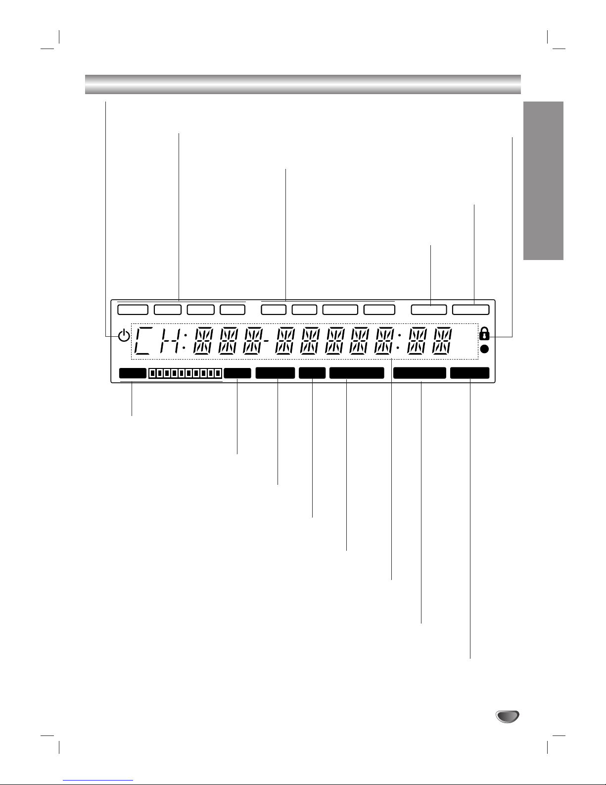
Display Window. . . . . . . . . . . . . . . . . . . . . . . . . . . . 7
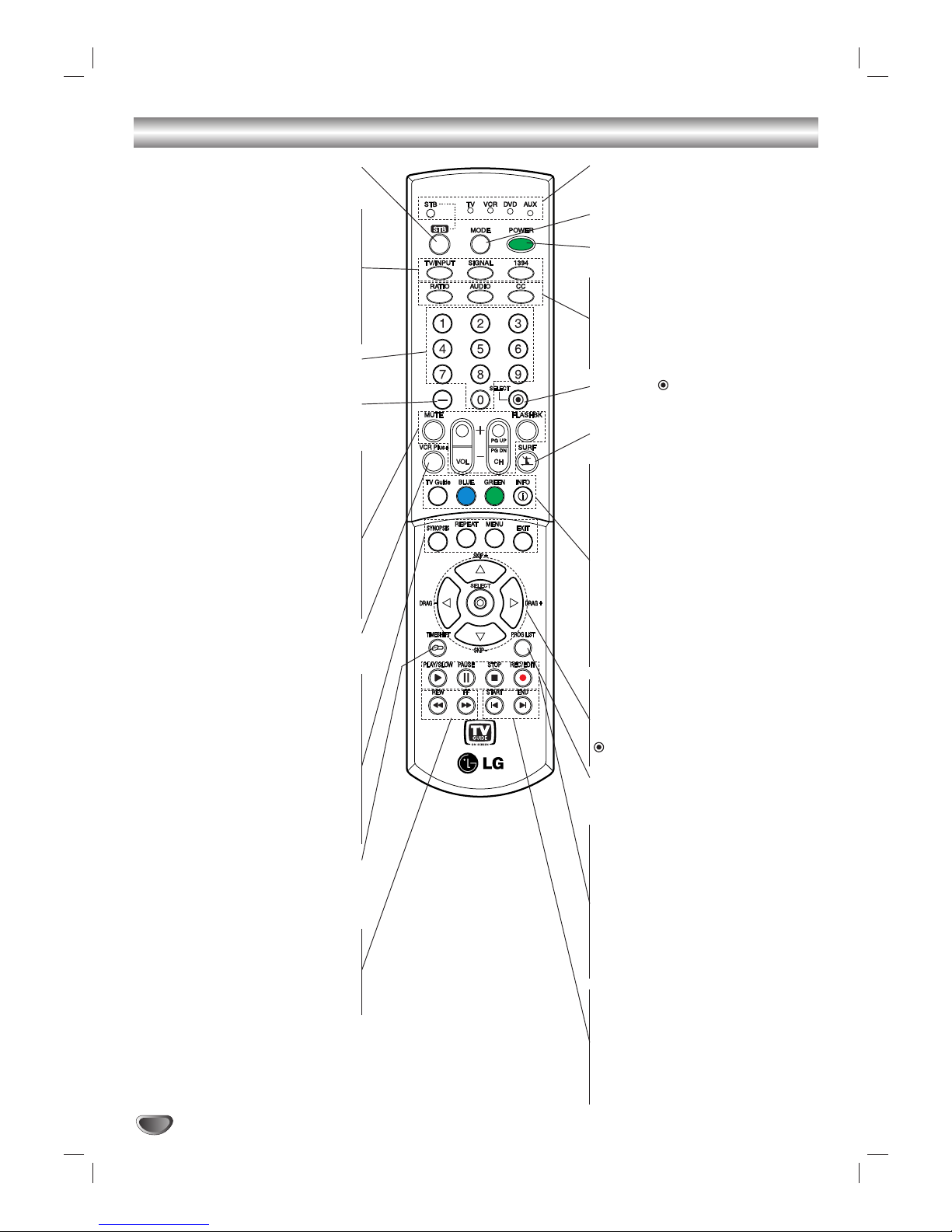
Remote Control Key Functions . . . . . . . . . . . . . . . 8
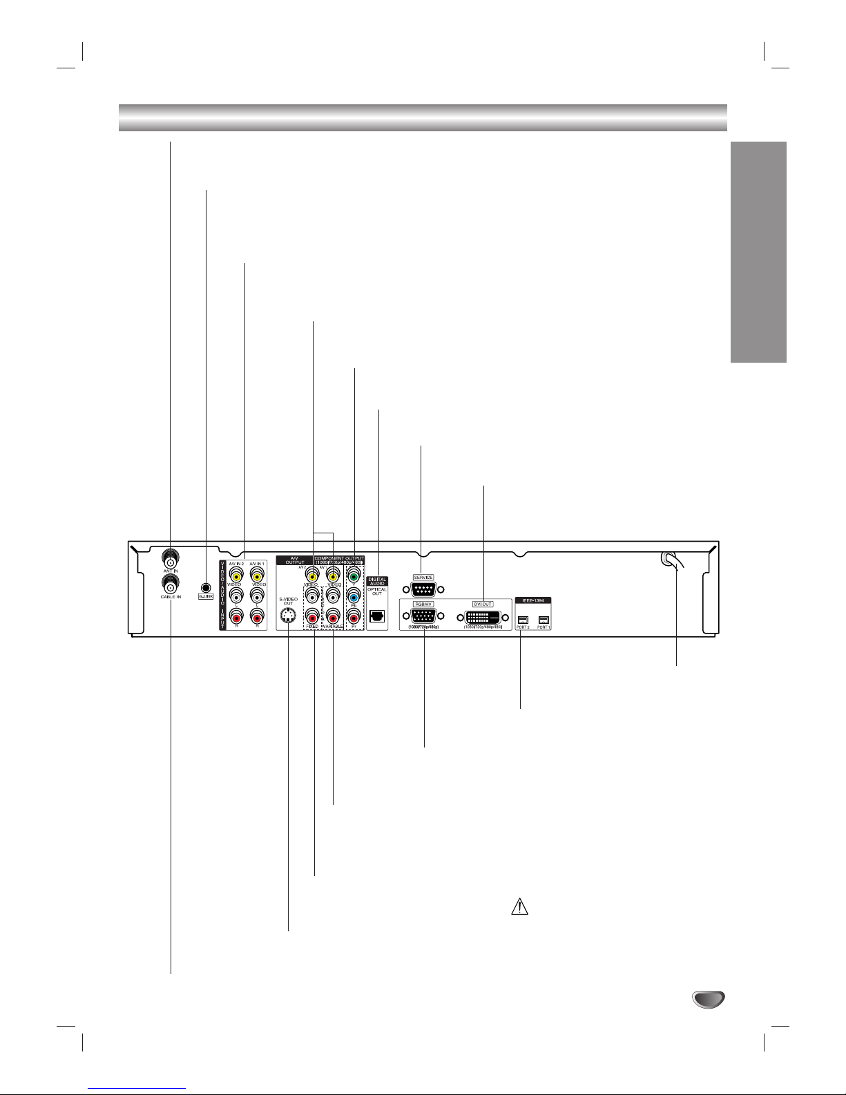
Connection Panel . . . . . . . . . . . . . . . . . . . . . . . . . . 9
INSTALLATION
Unpacking HD DVR and Accessories/
Connection Overview . . . . . . . . . . . . . . . . . . . . . . 10
Connections . . . . . . . . . . . . . . . . . . . . . . . . . . . 11-22
Antenna/CATV (Cable Service) Connections. . . . 11
Analog TV/Monitor Connections . . . . . . . . . . . . . 12
HD TV/Monitor Component (YPbPr) Connections
. . 13
HD TV/Monitor RGB Connections . . . . . . . . . . . 14
HD TV/Monitor DVI Connections . . . . . . . . . . . . 15
VCR Connections . . . . . . . . . . . . . . . . . . . . . . . 16
Amplifier (Receiver) Connections . . . . . . . . . . . . 17
Accessory Audio/Video (A/V) Connections to
the HD DVR. . . . . . . . . . . . . . . . . . . . . . . . . . . . 18
Cable Box Connections using “A/V IN 1” jacks
on the HD DVR . . . . . . . . . . . . . . . . . . . . . . . . . 19
Cable Box Connections using “A/V IN 1” jacks
and splitter. . . . . . . . . . . . . . . . . . . . . . . . . . . . . 20
Cable Box Connections using “CABLE IN” jack
on the HD DVR . . . . . . . . . . . . . . . . . . . . . . . . . 21
IEEE-1394 Connections . . . . . . . . . . . . . . . . . . . 22
Setting the Display Format Output . . . . . . . . . . . . 23
OPERATION
Normal Operation Overview. . . . . . . . . . . . . . . 24-26
2 Mega Pixels HDTV Reception . . . . . . . . . . . . . 24
Record now and view later. . . . . . . . . . . . . . . . . 24
Pause live TV . . . . . . . . . . . . . . . . . . . . . . . . . . 24
Seek a scene using the DRAG +/– feature . . . . . 24
Smart Skip. . . . . . . . . . . . . . . . . . . . . . . . . . . . . 25
Save your recordings to DVHS (Digital VHS) . . . 25
Recording capability with the IEEE-1394 connection
. 25
Channel Selection . . . . . . . . . . . . . . . . . . . . . . . 26
Sound Adjustment . . . . . . . . . . . . . . . . . . . . . . . 26
Signal . . . . . . . . . . . . . . . . . . . . . . . . . . . . . . . . 26
Menu Operation . . . . . . . . . . . . . . . . . . . . . . . . . . . 27
Basic Menu Operation . . . . . . . . . . . . . . . . . . . . 27
Setup Menu Operation . . . . . . . . . . . . . . . . . . 28-31
EZ Scan (Channel Search) . . . . . . . . . . . . . . . . 28
Ch. Edit (Add, Delete, Surf Channels) . . . . . . . . 28
DTV Signal . . . . . . . . . . . . . . . . . . . . . . . . . . . . 29
Channel Labels . . . . . . . . . . . . . . . . . . . . . . . . . 29
Input Source . . . . . . . . . . . . . . . . . . . . . . . . . . . 30
Auto Demo . . . . . . . . . . . . . . . . . . . . . . . . . . . . 30
Troubleshooting Options . . . . . . . . . . . . . . . . . . 31
Option Menu Operation . . . . . . . . . . . . . . . . . . 32-34
Audio Output . . . . . . . . . . . . . . . . . . . . . . . . . . . 32
Audio Language. . . . . . . . . . . . . . . . . . . . . . . . . 32
Clock . . . . . . . . . . . . . . . . . . . . . . . . . . . . . . . . . 32
Aspect Ratio . . . . . . . . . . . . . . . . . . . . . . . . . . . 33
On-screen Menu Language Setup.. . . . . . . . . . . 34
DVI Level. . . . . . . . . . . . . . . . . . . . . . . . . . . . . . 34
Caption Menu Operation . . . . . . . . . . . . . . . . . 35-37
Caption Settings, General Operation . . . . . . . . . 35
Caption . . . . . . . . . . . . . . . . . . . . . . . . . . . . . . . 36
Caption Option. . . . . . . . . . . . . . . . . . . . . . . . . . 37
Lock (Parental Control) Menu Operation. . . . . 38-42
Lock System . . . . . . . . . . . . . . . . . . . . . . . . . . . 38
Set Password . . . . . . . . . . . . . . . . . . . . . . . . . . 38
Block Ch. (Channel). . . . . . . . . . . . . . . . . . . . . . 39
Movie Rating . . . . . . . . . . . . . . . . . . . . . . . . . . . 39
TV Rating-Children . . . . . . . . . . . . . . . . . . . . . . 40
TV Rating-General . . . . . . . . . . . . . . . . . . . . . . . 41
Aux.Block . . . . . . . . . . . . . . . . . . . . . . . . . . . . . 42
DVR Menu Operation . . . . . . . . . . . . . . . . . . . . 43-45
TV Guide On Screen™ System . . . . . . . . . . . . . 43
Program List . . . . . . . . . . . . . . . . . . . . . . . . . . . 44
HDD Format . . . . . . . . . . . . . . . . . . . . . . . . . . . 45
Recording Quality . . . . . . . . . . . . . . . . . . . . . . . 45
Information Displays . . . . . . . . . . . . . . . . . . . . . . . 46
Channel Banner Display. . . . . . . . . . . . . . . . . . . 46
Program Information Display . . . . . . . . . . . . . . . 46
Recording Setup Operation . . . . . . . . . . . . . . . . . 47
Manual Recording . . . . . . . . . . . . . . . . . . . . . . . 47
Playback Operation . . . . . . . . . . . . . . . . . . . . . . . . 48
Timeshift (Pause, Live TV/Playback) Setup and
Operation . . . . . . . . . . . . . . . . . . . . . . . . . . . . . . . . 49
Bookmarking . . . . . . . . . . . . . . . . . . . . . . . . . . . 49
Clip Edit . . . . . . . . . . . . . . . . . . . . . . . . . . . . . . . . . 50
Clip Record . . . . . . . . . . . . . . . . . . . . . . . . . . . . . . 50
Smart Skip (+/-), Video Synopsis, Drag & Play. . . 51
IEEE-1394 Devices . . . . . . . . . . . . . . . . . . . . . . 52-53
List of Devices . . . . . . . . . . . . . . . . . . . . . . . . . . 52
Control Panel. . . . . . . . . . . . . . . . . . . . . . . . . . . 52
Record contents from DVHS to
the HD DVR’s HDD (Hard Disk Drive) . . . . . . . . 53
Control an MV Camcorder . . . . . . . . . . . . . . . . . 53
TV Guide On Screen™ System . . . . . . . . . . . . 54-60
Overview and Setup. . . . . . . . . . . . . . . . . . . . . . 54
Overview of downloads . . . . . . . . . . . . . . . . . . . 55
Grid Guide Layout. . . . . . . . . . . . . . . . . . . . . 56-57
SORT . . . . . . . . . . . . . . . . . . . . . . . . . . . . . . . . 58
FAVORITES/RECORD in LISTINGS. . . . . . . . . . 58
VCR Plus+ Recording . . . . . . . . . . . . . . . . . . . . 59
Canceling FAVORITES/RECORD. . . . . . . . . . . . 59
Channel Editor. . . . . . . . . . . . . . . . . . . . . . . . . . 60
On/Off Setup . . . . . . . . . . . . . . . . . . . . . . . . . . . 60
REFERENCE
Programming the Remote Control to
Operate Other Devices . . . . . . . . . . . . . . . . . . . 61-63
Troubleshooting . . . . . . . . . . . . . . . . . . . . . . . . . . 64
Specifications . . . . . . . . . . . . . . . . . . . . . . . . . . . . 65
Notes. . . . . . . . . . . . . . . . . . . . . . . . . . . . . . . . . 66-67
Warranty . . . . . . . . . . . . . . . . . . . . . . . . . Back Cover

6
Front Panel Controls
Remote Control Sensor
Receives signals from the remote control.
Arrow Buttons (33/ 44/ 11/ 22)
Navigate on-screen menus and adjust system settings and prefer-
ences.
Use the arrow buttons to move to a menu option and then use the
SELECT button to access it.
If no menu is displayed, the
1/ 2
buttons control the volume setting
and the
3/ 4
buttons select channels.
Power
Turns the HD DVR on and off.
Display Window
EXIT
Clears all on-screen displays and returns to
normal viewing from any menu.
SELECT
If the main menu is displayed, pressing the SELECT button will activate
the highlighted MENU option. If the SELECT button is pressed while
you are in normal viewing, the channel banner will be displayed.
MENU
Shows the main menu on the screen. You can return to
normal viewing by pressing the EXIT button.
GUIDE
Shows station and program information on the screen.
To remove the banner, press the button again.
DISPLAY FORMAT
Sets the output resolution to 1080i, 720p, 480p, or 480i formats and chooses
the correct display format for your TV or monitor. (Refer to page 23.)
RECORD
Activates Instant Timer Recording.
To stop recording, press the button again.

INTRODUCTION
7
Display Window
1080i 720p 480p 480i DVI RGB YPBPRVideo 1394 Cable
AM
PM
HDD
FULL
Record Play Time Shift Reserved Guide
Standby indicator
Lights when the HD DVR is turned off.
Resolution indicators
Indicates the output resolution.
Connection indicators
Indicates the output connection.
Cable/Air Indicator
Lights when the HD DVR is
tuned to a cable channel.
Lock Indicator
Lights if the current channel or program is locked.
IEEE-1394 Indicator
Lights when one or more
IEEE-1394 devices are
connected.
Status Indicators
Indicate channel number, volume level, etc.
Record Indicator
Lights when the unit is recording.
Play Indicator
Lights during playback.
Time Shift Indicator
Lights when the unit is timeshifting.
Disk Full Indicator
Lights when all the disk space is
used.
Hard Disk Indicator
Indicates hard disk
space used.
Reserved REC Indicator
Lights when the unit is in timer recording or a
timer recording is programmed.
Guide Indicator
Lights when this unit is receiving TV Guide On Screen™ data.

8
Remote Control Key Functions
STB
Selects STB (HD DVR) operational mode
on remote control.
TV/INPUT
Selects the TV signal source (Tuner or
AUX A/V input).
SIGNAL
Shows signal strength of the current
channel.
1394
Shows list of connected IEEE-1394
devices.
Numbers
Chooses channels and enters program-
ming information.
Dash (-)
Enters a channel number for multiple
program channels such as 2-1, 2-2, etc.
MUTE
Temporarily turns sound OFF, press again
to restore.
VOL (Volume) (+/-)
Increases / decreases sound level.
CH (Channel) (+/–), PG UP/DN
Cycles a memorized channel. Pressing
the PG UP/DN buttons pages through the
Program Guide or Channel Edit menu.
FLASHBK
Returns to the last channel viewed.
VCR Plus+
Activates Manual Reservation feature for
recording a program.
SYNOPSIS
Activates digest view mode.
REPEAT
Repeats sequence during playback.
MENU
Accesses or closes main menu.
EXIT
Removes all on-screen displays and
returns to TV viewing from any menu or
removes the progress bar during
playback.
TIMESHIFT
Activates pause live tv/playback (timeshift)
for live TV and marks any point during
timeshift and playback.
REW
Rewinds at 5 different speeds up to 300
times the speed of normal playback.
FF
Fast Forwards at 5 different speeds up to
300 times the speed of normal playback.
Mode indicator
Indicates operational mode of remote con-
trol.
MODE
Selects operational mode for remote control.
POWER
Turns the HD DVR ON and OFF.
RATIO
Changes the picture aspect ratio.
AUDIO
Selects audio language options.
CC
Turns closed captions on and off.
SELECT ( )
Completes channel number input and
promptly tunes to selected channel.
SURF
Tunes to your surf channels.
TV GUIDE
Turns TV Guide On Screen™ System ON
and OFF.
BLUE, GREEN
TV Guide On Screen System specific
functions.
While in TV Mode and not playing, record-
ing, timeshifting, press BLUE to tune to
the first channel in the favorite list of TV
Guide. Each press will result in tuning to
the next channel in the list.
INFO
Shows current station and program infor-
mation on screen.
Arrow Buttons (33/ 44/ 11/ 22),
DRAG + / –, SKIP + / -
Selects options in a menu. Smart skip and
drag&play in trick play mode.
(SELECT)
Acknowledges menu selection.
PROG. LIST
Shows list of recorded programs in
thumbnails.
PLAY/SLOW
Starts playback or slow 1/2 speed
playback.
PAUSE
Pauses playback.
STOP
Stops playback or recording.
RECORD/EDIT
Starts recording or edits a recorded
program.
START
Returns to the start position of current
playback or a repeated segment.
END
Moves to the end point of a program dur-
ing playback or returns to the current TV
program live broadcast during pause
timeshift.

9
INTRODUCTION
Connection Panel
Do not touch the inner pins of the
jacks on the rear panel.
Electrostatic discharge may cause
permanent damage to the unit.
AC Power Cord
Plug into the power source.
ANT IN
Connect to over-the-air outdoor/indoor antenna.
G-LINK®
Gemstar cable box control connector. Connect G-LINK cable (supplied with your HD DVR) to
control a Cable Box using the TV Guide On Screen™ feature.
Note: If there is a “demo pin” in the jack, remove it to disable demo mode.
AUDIO/VIDEO INPUT 1, 2
Connect audio/video output of an external source (Audio system, TV/Monitor,
VCR, Camcorder).
VIDEO OUT 1, 2
Connect to TV/Monitor with composite video inputs.
COMPONENT OUTPUT
Connect to TV/Monitor with YPbPr inputs.
AUTHORIZED SERVICE ONLY
Is used only for authorized service purposes.
DVI OUT
Connect to TV/Monitor with DVI port.
CABLE IN
Connect to cable TV (CATV) signal source.
S-VIDEO OUT
Connect to TV/Monitor with S-Video
input.
Fixed “volume”AUDIO OUT (Left/Right)
Connect to a TV, amplifier, receiver or stereo system.
You cannot adjust the volume of this audio out on HD DVR.
Variable “volume”AUDIO OUT (Left/Right)
Connect to a TV, amplifier, receiver or stereo system.
You can adjust the volume of this audio out on HD DVR.
RGB OUT
Connect to TV/Monitor with RGB input.
IEEE-1394
Connect to IEEE-1394 equipment.
DIGITAL AUDIO OUT (OPTICAL)
Connect to digital (optical) audio equipment.

10
Unpacking HD DVR and Accessories/Connection Overview
Audio/Video Jacks and Cables
The Audio/Video jacks provide excellent picture and sound quality. They are
used for making most Audio/Video connections between components. The
Audio/Video jacks may be color coded (yellow for video, red for right audio,
and white for left audio). If your component has only one input for audio
(mono), connect it to the left (white L/mono) audio jack on the HD DVR.
Component Video Out Jacks and Cables
Component Video Cables are used to connect the HD DVR to an industry
standard YPbPr compatible HD Monitor (green for Y, blue for Pb, and red
for Pr). Remember to also connect the left and right audio cables. The
YPbPr Component jacks carry only the picture signals, not the sound.
DVI-HDTV Cable
DVI cable is used to connect the HD DVR to an industry standard DVI-
HDTV compatible HD monitor. Remember to also connect the left and right
audio cables. A DVI jack carries only the video signals, not the audio.
G-LINK Cable
G-LINK Cable is used to control cable box with the TV Guide On Screen™
System.
TV Guide On Screen System Demo Pin and Tag
Demo Pin consists of a tag and rivet that prevent the TV Guide On Screen
System from operating and instead show the Retail Demo feature contained
in the HD DVR firmware.
You must remove the Demo Pin from the G-LINK jack and insert the IR
Controller in the G-LINK port. This disables the retail Demo feature and
allows normal Host device operation.
Remote Control
In addition to the HD DVR, the remote control can be programmed to
operate other IR controlled external devices.
Remote Control Operating Range
Point the remote control at the remote sensor and press the buttons.
Distance: About 23 ft (7 m) from the front of the remote sensor.
Angle: About 30° in each direction of the front of the remote sensor.
Remote Control Battery Installation
Remove the battery cover on the rear of the remote control, and install two
batteries (size AA) with and matched correctly.
Caution
Do not mix old and new batteries. Never mix different types of batteries
(standard, alkaline, etc.).
Make sure you have received all the accessories listed below with the HD DVR.
AA
AA
DEMO PIN
HDTV DIGITAL VIDEO RECORDER / RECEIVER (HD DVR)
This HD DVR is capable of receiving signals from cable and/or over-the-air antenna sources.
Included with the HD DVR are the following accessories.
RF Cable, Audio Cable/Video Cable/Component (YPbPr) Cable/DVI-D Cable/G-LINK®Cable
Remote Control and 2 AA Batteries

INSTALLATION
11
Connections
Antenna/CATV (Cable Service) Connections
Before connecting an antenna and/or cable service
The LST-3410A is a high performance, high gain system intended for operation under normal or weak signal conditions, providing
the best reception with its optimum gain capability. You can find HDTV channels/content information for your local broadcast area
by going to Zenith website “WWW.ZENITH.COM” and clicking on “HDTV Program Schedule” under HDTV.
11
Connect your Antenna to the “ANT IN” jack on the HD DVR with a coaxial RF cable.
22
Connect your cable TV (CATV) service to the “CABLE IN” jack on the HD DVR with a coaxial RF cable.
Cable TV
Wall Jack Panel
HD DVR Connection Panel
Antenna

Connections (Continued)
12
Display Formats Overview
•The HD DVR offers various display formats and multiple video outputs. When the HD DVR is connected to A/V
systems, the HD DVR can provide video signal formats 1080i, 720p, 480p, or 480i.
•The HD DVR has digital audio outputs; Dolby Digital 5.1 and PCM. The HD DVR sends out digital audio signal to
OPTICAL audio output.
Analog TV/Monitor Connections
11
Connect your Antenna to the “ANT IN” jack on the HD DVR using a coaxial RF cable.
22
Connect your cable TV (CATV) service to the “CABLE IN” jack on the HD DVR with a coaxial RF cable.
33
Connect the “AUDIO OUT” and “VIDEO OUT” jacks from the HD DVR to the “A/V IN” jacks on your TV/Monitor
with RCA-type cables. If your TV/Monitor is equipped with an S-Video jack, use the S-VIDEO OUT connection
instead. (The Output Selection must be set to VIDEO, refer to Setting the Display Format on page 23).
ote
S-Video cable is not included.
Cable TV
Wall Jack Panel
Antenna
OR
L
R
AUDIO INPUT
VIDEO
INPUT
S-VIDEO
INPUT
ANTENNA
INPUT
TV/Monitor Connection Panel
HD DVR Connection Panel

INSTALLATION
13
Connections (Continued)
HD TV/Monitor Component (YPbPr) Connections
11
Connect your Antenna to the “ANT IN” jack on the HD DVR with a coaxial RF cable.
22
Connect your cable TV (CATV) service to the “CABLE IN” jack on the HD DVR with a coaxial RF cable.
33
Connect the “COMPONENT OUT” jacks from the HD DVR to the “COMPONENT IN” jacks on your TV/Monitor
with RCA-type cables. (The Output Selection must be set to YPbPr, refer to Setting the Display Format on page
23).
44
Connect the L/R “AUDIO OUT” jacks from the HD DVR to the L/R “AUDIO IN” jacks on your TV/Monitor with
RCA-type cables. If your TV/Monitor is equipped with a “Digital Audio Input (Optical)” jack, connect to “DIGITAL
AUDIO (OPTICAL OUT)” jack.
Cable TV
Wall Jack Panel
Antenna
Pr
Pb
Y
COMPONENT VIDEO INPUT
R
L
AUDIO INPUT
VIDEO
INPUT
ANTENNA
INPUT
HD Ready TV/Monitor Connection Panel
HD DVR Connection Panel
DIGITAL INPUT
OPTICAL
OR

14
Connections (Continued)
HD TV/Monitor RGB Connections
11
Connect your Antenna to the “ANT IN” jack on the HD DVR with a coaxial RF cable.
22
Connect your cable TV (CATV) service to the “CABLE IN” jack on the HD DVR with a coaxial RF cable.
33
Using a RGB (D-SUB type) cable, connect the “RGB OUT” jack from the HD DVR to the “RGB IN” jack on your
TV/Monitor. (The Output Selection must be set to RGB, refer to Setting the Display Format on page 23).
44
Connect the L/R “AUDIO OUT” jacks from the HD DVR to the L/R “AUDIO IN” jacks on your TV/Monitor with
standard RCA-type cables.
ote
The RGB output is useable only if 1080i, 720p, or 480p display format is selected.
Cable TV
Wall Jack Panel
Antenna
R
L
AUDIO INPUT RGB INPUT
VIDEO
INPUT
S-VIDEO
INPUT
ANTENNA
INPUT
HD Ready TV/Monitor Connection Panel
HD DVR Connection Panel

INSTALLATION
15
Connections (Continued)
HD TV/Monitor DVI Connections
11
Connect your Antenna to the “ANT IN” jack on the HD DVR with a coaxial RF cable.
22
Connect your cable TV (CATV) service to the “CABLE IN” jack on the HD DVR with a coaxial RF cable.
33
Connect the “DVI OUT” jack from the HD DVR to the “DVI IN” jack on your TV/Monitor with a DVI-D type con-
nector. (The Output Selection must be set to DVI, refer to Setting the Display Format on page 23.)
44
Connect the L/R “AUDIO OUT” jacks from the HD DVR to the L/R “AUDIO IN” jacks on your TV/Monitor with
standard RCA-type cables.
otes
• A DVI-HDTV input is one that is compliant with EIA-861 and HDCP specifications. Check your TV or monitor’s
user manual to find out if the TV or monitor’s DVI input is compliant with these specifications.
• Some HD Monitors designed for PC applications using DVI-D may not work with this connection.
Cable TV
Wall Jack Panel
Antenna
L
R
AUDIO INPUT DVI-HDTV INPUT
VIDEO
INPUT
S-VIDEO
INPUT
ANTENNA
INPUT
HD Ready TV/Monitor Connection Panel
HD DVR Connection Panel

16
Connections (Continued)
VCR Connections
Connect the L/R “AUDIO OUT” jacks and “VIDEO OUT” jack from the HD DVR to the “A/V in” jacks on your VCR
with standard RCA-type cables. (If your VCR is equipped with an S-Video jack, you can use the “S-VIDEO” connec-
tion with an “S-Video” cable instead.)
Cautions
•To record the HD DVR’s contents to VCR, the Output Selection must be set to VIDEO. Refer to Setting the
Display Format on page 23.
•The VCR will record an on screen display onto the tape during recording if:
the channel is changed with CH (+/–)
the sound level is adjusted with VOL (+/–)
or by pressing the SELECT button, etc.
R
L
AUDIO INPUT VIDEO
INPUT
VCR Connection Panel
HD DVR Connection Panel

INSTALLATION
17
Connections (Continued)
Amplifier (Receiver) Connections
Connection for an amplifier equipped with two channel analog stereo or Dolby Surround
Connect the left and right AUDIO OUT jacks from the HD DVR to the audio left and right in jacks on your amplifier,
receiver, or stereo system, with the audio cables supplied.
Connection for an amplifier equipped with two channel digital stereo (PCM) or for an
Audio/ Video receiver equipped with a multi-channel decoder (Dolby Digital™)
Connect the HD DVR’s DIGITAL AUDIO OUT jack (OPTICAL) to the corresponding input jack on your amplifier. Use
an optional digital (optical) audio cable.
Digital Multi-channel sound
A digital multi-channel connection provides the best sound quality. For this you need a multi-channel Audio/Video
receiver that supports one or more of the audio formats supported by your HD DVR (Dolby Digital). Check the
receiver manual and the logos on the front of the receiver.
R
L
AUDIO INPUT DIGITAL INPUT
OPTICAL
HD DVR Connection Panel
Amplifier (Receiver) Connection Panel
OR

Connections (Continued)
18
Accessory Audio/Video (A/V) Connections to the HD DVR
Connect the A/V IN 1 or A/V IN 2 jacks from the HD DVR to the audio/video out jacks on your accessory compo-
nent, using optional audio/video cables.
L
R
AUDIO OUTPUT VIDEO
OUTPUT
HD DVR Connection Panel
Accessory
Connection
Panel
Camcorder Game Device DVD Player

INSTALLATION
19
Connections (Continued)
Cable Box Connections using “A/V IN 1”jacks on the HD DVR
Use your HD DVR to control your cable box with the TV Guide On Screen™ System.
Locate the G-LINK®jack. This jack is for the G-LINK cable. Insert the connector into the G-LINK jack.
Note: If there is a “demo pin” in the jack, remove it to disable demo mode.
Place the other end of the G-LINK cable with the G-LINK wand in front of your Cable Box in such a way as to allow for
an unrestricted path for the IR (infrared) signal to be able to reach the front panel of the Cable Box.
ote
See page 54 for TV Guide On Screen System information and set up.
11
Connect your cable TV (CATV) service to the “CABLE IN” jack on the Cable Box with a coaxial RF cable.
22
Connect the “AUDIO OUT” and “VIDEO OUT” jacks from your Cable Box to the “A/V IN 1” jack on the HD DVR
with standard RCA-type cables.
ote
The HD DVR cannot receive program information if you connect the “VIDEO OUT” jack from your Cable Box to the
“A/V IN 2” jack on the HD DVR.
33
You can watch terrestrial digital broadcasting if you connect your Antenna to the “ANT IN” jack on the HD DVR
with a coaxial RF cable.
44
You can watch unscrambled digital cable broadcasting if you connect “LOOP OUT” from the cable box to the
“CABLE IN” jack on the HD DVR with a coaxial RF cable.
otes
• Select “Cable box” menu option to watch cable programming.
• Select “Digital” menu option to watch unscrambled digital terrestrial/cable programming.
L
R
AUDIO OUTPUT
VIDEO
OUTPUT
HD DVR Connection Panel
Cable Box Connection Panel
Cable Box (front view)
Cable Box
(side view) 1/2" to 1"
IR Sensor
Cable Box Controller
Cable TV
Wall Jack Panel
Antenna CABLE
INPUT LOOP OUT

20
Connections (Continued)
Cable Box Connections using “A/V IN 1”jacks and splitter
You can use a splitter if you cable box does not have a “LOOP OUT” jack.
ote
A splitter is not included in the package and must be purchased separately.
11
Connect the your cable TV (CATV) service to the splitter and connect the splitter to the “CABLE IN” jack on
your Cable Box and to the “CABLE IN” jack on the HD DVR with coaxial RF cables.
22
Connect the “AUDIO OUT” and “VIDEO OUT” jacks from your Cable Box to the “A/V IN 1” jacks on the HD
DVR with standard RCA-type cables.
ote
The HD DVR cannot receive program information if you connect the “VIDEO OUT” jack from your Cable Box to the
“A/V IN 2” jack on the HD DVR.
33
You can watch terrestrial digital broadcasting if you connect your Antenna to the “ANT IN” jack on the HD DVR
with a coaxial RF cable.
otes
• Select “Cable box” menu option to watch cable programming via cable box.
• Select “Digital” menu option to watch unscrambled digital terrestrial/cable programming.
• You can watch unscrambled digital cable broadcasting if you connect the splitter to the “CABLE IN” jack on the
HD DVR with a coaxial RF cable
L
R
AUDIO OUTPUT
VIDEO
OUTPUT
HD DVR Connection Panel
Cable Box Connection Panel
Cable Box (front view) IR Sensor
Cable Box Controller
Cable TV
Wall Jack Panel
Antenna
Splitter
CABLE
INPUT LOOP OUT
Cable Box
(side view) 1/2" to 1"
Other manuals for LST-3410A
3
Table of contents
Other LG Receiver manuals