ExtremeView Magnum XV 3300 User manual


Contents
2
Declaration of Conformity --------------------------------------------------------------------------------- 3
General Information ----------------------------------------------------------------------------------------- 7
Safety and Precaution ------------------------------------------------------------------------------ 7
Accessories -------------------------------------------------------------------------------------------- 9
Remote Control Unit --------------------------------------------------------------------------------------- 10
System Connection ---------------------------------------------------------------------------------------- 11
Front Panel ------------------------------------------------------------------------------------------- 12
Rear Panel ------------------------------------------------------------------------------------------- 12
Connecting your System -------------------------------------------------------------------------- 13
Menu Structure ---------------------------------------------------------------------------------------------- 15
Menu Guide --------------------------------------------------------------------------------------------------- 16
Installation -------------------------------------------------------------------------------------------- 16
Channel Guide -------------------------------------------------------------------------------------- 22
Channel Manager ---------------------------------------------------------------------------------- 25
System Setting -------------------------------------------------------------------------------------- 28
Games / Memo -------------------------------------------------------------------------------------- 32
Embedded CAS -------------------------------------------------------------------------------- 34
Functions Guide -------------------------------------------------------------------------------------------- 35
List Menu --------------------------------------------------------------------------------------------- 35
Closed Caption ------------------------------------------------------------------------------------- 37
Info Bar ---------------------------------------------------------------------------------------------- 37
Signal -------------------------------------------------------------------------------------------------- 37
Zoom -------------------------------------------------------------------------------------------------- 38
Quick Edit -------------------------------------------------------------------------------------------- 38
Audio Language ------------------------------------------------------------------------------------ 38
Technical Specification ----------------------------------------------------------------------------------- 39
Trouble Shooting Guide ---------------------------------------------------------------------------------- 42
Universal RCU --------------------------------------------------------------------------------------- 44
Universal Remote Control Function list -------------------------------------------------------- 44
Universal Remote Control Unit Code ---------------------------------------------------------- 45

Declaration of Conformity
3
FCC Rule : TESTED TO COMPLY WITH FCC PART 15, CLASS B OPERATING
ENVIRONMENT : FOR HOME OR OFFICE USE
Caution : Any changes or modifications in construction of this device which are not
expressly approved by the party responsible for compliance could void the
user’s authority to operate the equipment.
Note : This equipment has been tested and found to comply with the limits for a
class B digital device, pursuant to part 15 of the FCC rules. These limit are
designed to provide reasonable protection against harmful interference in a
residential installation. This equipment generates, user and can radiate radio
frequency Energy and, if not installed and used in accordance with the
instructions, may cause harmful interference to radio communications.
However, there is no guarantee that interference will not occur in a particular
installation, if this equipment does cause harmful interference to radio or
television reception, which can be determined by turning the equipment off and
on, the user is encouraged to try to correct the interference by one or more of
the following measures :
1. Reorient / Relocate the receiving antenna.
2. Increase the separation between the equipment and receiver.
3. Connect the equipment into an outlet on a circuit difference from that to
which the receiver is connected.
4. Consult the dealer or an experience radio / TV technician for help.
This device complies with part 15 of the FCC rules. Operation is subject to
the following two conditions : (1) This device may not cause harmful interference,
and (2) this device must accept any interference received, including interference
that may cause undesired operation.
This satellite receiver provides display of television closed captioning in accordance
with 15.119 of the FCC rules.
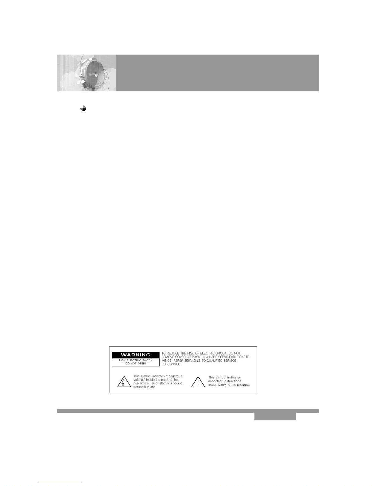
RISK OF ELECTRIC SHOCK DO NOT OPEN
CAUTION
CAUTION : TO REDUCE THE RISK OF ELEC
TRIC SHOCK, DO NOT REMOVE COVER
(OR BACK). NO USER SERVICEABLE PARTS
INSIDE. REFER SERVICING TO QUALIFIED
SERVICE PERSONAL.
This symbol indicates high voltage is
Present inside. It is dangerous to make
Any kind of contact with any inside
Part of this product.
This symbol alerts you that important
Literature concerning operation and
maintenance have been included with
This product.

①Read these instructions.
②Keep these instructions.
③Heed all warnings.
④Follow all instructions.
⑤Do not use this apparatus near water.
⑥Clean only with dry cloth.
⑦Do not block any ventilation opening. Install in accordance with the manufacture’s
instruction.
⑧Do not install near any heat sources such as radiators, heat registers, stoves or
other apparatus (including amplifiers) that produce heat.
⑨Do not defeat the safety purpose of the polarized or grounding type plug A polarized
plug has two blades with one wider than the other. A grounding type plug has two
blades and a third grounding prong. The wide blade or third prong are provided
for your safety. If the provided plug does not fit into your outlet consult an electrician
for replacement of the obsolete outlet
⑩Protect the power cord from being walked on or
pinched particularly at plug convenience
receptacles and the point where they exit from
the apparatus.
⑪Only use attachment accessories specified by
the manufacturer.
⑫Use only with the cart, stand, tripod, bracket
or table specified by the manufacturer,
or sold with the apparatus. When a cart is used,
use caution when moving the cart/apparatus
combination to avoid injury from tip-over.
⑬Unplug this apparatus during lightning storms or when unused for long periods
of time.
⑭Refer all servicing to qualified service personal. Servicing is required when the
apparatus has been damaged in anyway, such as power-supply cord or plug is
damaged, liquid has been spilled or objects have fallen into the apparatus,
the apparatus has been exposed to rain or moisture does not operate normally
or has been dropped.
WARNING : To reduce the risk of fire or electric shock, do not expose this
apparatus to rain or moisture.
Important Safety Instructions
4
Declaration of Conformity

RIESGO DE DESCARGA ELÉCTRICA. NO ABRIR
PRECAUCIÓN
PRECAUCIÓN : PARAREDUCIR EL RIESGO
DE DESCARGA ELÉCTRICA. NO RETIRE LA
CUBIERTA(O LA PARTE POSTERIOR).
EN EL INTERIOR DE LA UNIDAD NO HAY
PARTES QUE PUEDAN SER MANTENIDAS
POR EL USUARIO. CONSULTE AL PERSONAL
DE SERVICIO TÉCNICO CALIFICADO.
Este simbolo indica la presencia de
alta tensión en el interior. Es
peligroso hacer cualquier tipo de
contacto con alguna de las piezas
internas de la unidad. Este simbolo
indica que se ha incluido bibliografia
impotante sobre el funcionamiento y
el mantenimiento de la unidad.
Este dispositivo cumple con la parte 15 de las Normas de la FCC. El
funcionamiento está sujeto a las dos condiciones siguientes : (1) Este dispositivo
no puede causar interferencias perjudiciales, y (2) Este dispositivo debe aceptar
cualquier interferencia que pueda causar un funcionamiento no deseado.
Este receptor satelital proporcióna la visualizacion de subtítulos cerrados de
televisión de acuerdo con el artículo 15.119 de las Notmas de la FCC.
5
Declaration of Conformity

①Lea estas instrucciones.
②Guarde estas instrucciones.
③Preste atencion a todas las advertencias.
④Siga todas las instrucciones.
⑤No use la unidad cerca del agua.
⑥Límpiela sólo con un paño seco.
⑦No bloquee las aberturas de ventilación. Realice la instalación de acuerdo con las
instrucciones del fabricante.
⑧No instale la unidad cerca de ninguna fuente de calor, como radiadores, medidores
de calor uotros equipos(incluyendo amplificadores) que puedan generar calor.
⑨No ignore el objetivo de seguridad del enchufe polarizado o de puesta a tierra.
El enchufe polarizado tiene dos contactores, uno más ancho que el otro.
El enchufe de puesta a tiene dos conectores y una clavija de puesta a tierra.
El conector ancho de la clavija se provee para resguardar su seguridad.
Si el enchufe provisto no encaja en la toma de corriente, consulte a un electricista
para reempalazar la toma.
⑩Proteja el cable de suministro eléctrico de manera
que no se puedan pisar o aplastar, especialmenye
junto al enchufe, los receptáculos apropiados y el
punto donde el cable sale de la unidad.
⑪Solamente use accesorios o equipamiento
especificado por el fabricante.
⑫Use sólo una mesita de ruedas, soporte, trípode,
repisa o mesa recomendada por el fabricante o
que se venda con la unidad. Tenga cuidado
cuando mueva la mesita con ruedas con la unidad para evitar que se vuelque.
⑬Desenchufe la unidad durante tormentas eléctricaas o cuando no se use durante
largos períodos.
⑭Todas las reparaciones deben efectuarse por un técnico de servicio calificado.
Es necesario realizar el servicio técnico si la unidad se ha dañado, como por
ejemplo si el enchufe o el cable de alimentación están dañados, si se ha
derramado líquido sobre la unidad o si ha caído algún objeto dentro de ella,
si la unidad ha quedado expuesta a la lluvia o al agua, no funciona de modo
normal o se ha caido.
Información importante sobre seguridad
6
Declaration of Conformity

◈MAINS SUPPLY
Use only 100 - 250VAC 50/60Hz.
◈OVERLOADING
Do not overload a wall outlet, extension cord or adapter as this may result in fire
electric shock.
◈LIQUIDS
Do not be exposed to dripping or splashing and that no objects filled with
liquids, such as vases, shall be placed on the apparatus.
◈CLEANING
1. Always disconnect the STB power cord from the outlet before cleaning.
2. Use a light damp cloth (no solvents) to dust off the STB.
◈VENTILATION
1. The slots on top of the STB must be left uncovered to allow proper airflow to
the unit.
2. Do not stand the STB on soft furnishings or carpets.
3. Do not expose the STB to direct sunlight or do not place it near a heater.
4. Do not stack electronic equipments on top of the STB.
5. Do not use this appliance in airtight area.
6. Do not open the top cover.
◈CABLE
Use standard certified cables to prevent any malfunction of the STB.
Safety and Precautions
Thank you for purchasing the digital satellite receiver.
For your safety and proper operation, please take time reading this manual fully before
installing and operating the receiver.
We hope you will be able to take advantage of the numerous functions with the help of
this manual.
General Information
7

◈ATTACHMENTS
Do not use any attachments that are not recommended as these may cause
hazard or damage to the STB.
◈CONNECTION TO THE SATELLITE DISH LNB
Disconnect the STB from the mains before connecting or disconnecting the
cables from the satellite dish.
Failure to do so can damage the LNB.
◈CONNECTION TO THE TV
Disconnect the STB from the mains before connecting or disconnecting the
cables from the TV.
Failure to do so can damage the TV.
◈EARTHING
The LNB cable MUST BE EARTHED to the system earth for the satellite dish.
The earthing system must comply with SABS 061.
◈LOCATION
Place the STB indoor in order not to expose to lightening, rain or sunlight.
◈SERVICING
1. Do not attempt to service this product yourself.
2. Refer all servicing to qualified service representatives
NOTICE : The power remains on even when the switch is turned off.
Safety and Precautions
General Information
8

Check the following accessories when you open the box
User’s Manual
RCA to RCA cable
The device, packaging material and batteries must never be disposed of
with household.
Please obtain appropriate information about regulations in your
community, and dispose of all in accordance with regulations at the
separate locations provided.
Accessories
Batteries
General Information
RCU
DiSEqC SW
Serial cable
9

INFO (INFORMATION)
Display channel status or
various program information of
current service.
TV / RADIO
Receiver switches between TV
and Radio channels.
CC (Closed Caption)
Display the Closed caption
MUTE
Enable or disable audio
NUMERIC KEYS :
Select channels by channel
numbers or enter programming
parameters.
TIMER
Display the reservation list
Recall (Previous)
Return to the previous menu,
status or channel
GUIDE Display the TV/Radio
Electronic Program Guide
VOL Up/Down
(Page Up/Down)
Increase or decrease the
volume. And move left or right
highlight marked cursor.
Page scrolling in
channel/satellite list menu.
CH Up/Down
Tune to the next or previous
channel. And move up or down
highlight marked cursor.
MENU
Display the Main Menu EXIT Cancel the user
selection
OK
Select menu option, or to
updated on entry and to enter
List menu
SLEEP (Blue Key)
Operate sleep(auto power off)
mode
AUDIO (Yellow Key)
Select audio mode (left, right,
stereo, language)
Signal
Display the signal and quality
SAT LIST
Display the satellite list
FAV (Favorite)
Set receiver to favorite service
mode, display the favorite
channel.
FIND
Quick Edit, Find(Sort) CH.name
Power
Power on, standby mode.
REW(◀◀) Rewind a
program PLAY(▶) At the F.list selected
file, then play
FWD(▶▶)
Fast forwards a
program.
STOP(■)
Stop a program
PAUSE (Red Key)
Pause screen.
REC
Press to start record
PAUSE(II)
Pause a program
CH LIST
Display the channel list
F1 Option key
To toggle RF. Mod. CH3/CH4
TV/SAT
Receiver switches between TV
and Satellite receive mode.
MOSAIC (Multi Picture)
Display multi channel on screen.
Remote Control Unit
ZOOM (Green Key)
Operated zoom function in live
and still mode
TV/DVD/AUX/SAT
Select other equipment
10

Front Panel
NOTICE :
1. Current time is based on the TDT(Time and Date Table) at the stream of the
current service. If the TDT information is not correct, current time might be
incorrect.
2. Please do not insert metal or alien substance into the slot for the modules
and Smartcards. In doing so can cause damage to the STB and reduce its life
span.
System Connection
◈Normal Display :
-On
-STANDBY
- Channel Number
- Channel Name
◈Tact switch : Standby On/Off, CH UP/DOWN, Menu, OK, Vol. UP/DOWN
◈Smart Interface slot : 1 Smart card slot (Xcrypt Embedded)
11

Rear Panel
Please refer to the diagram above for all possible connections of your receiver
Do not connect the unit to the mains socket until all other connections
have been made and checked.
1) IF INPUT : This port is to connect the coaxial cable from LNB of your Dish.
2) IF OUT : This enables the connection of an Analogue receiver.
3) S-Video : This Din connectors is used to connect your TV through
S-Video Cable.
4) Component out : This RCA connector is used to connect your TV through
RCA cable. (Y/Pb/Pr component output)
5) VIDEO : This RCA connector is used to connect your TV through RCA cable.
6) AUDIO R/L : These RCA connectors are used to connect your TV through
RCA cable or any external audio amp or system.
7) ANT IN : To connect the terrestrial antenna
8) TV OUT : To connect the RF signal to a RF(ANT) input e.g. VCR, TV.
9) S/PDIF : This is used to connect with Digital audio amplifier.
10) RS 232C SERIAL PORT : This is used to connect your receiver with a
computer or other STB through a serial cable.
REAR PANEL
①② ③ ④⑤⑥⑦⑧ ⑨ ⑩
12

Connecting Your System
System Connection
◈TV Only
◈With External Audio / Hi-Fi System
yTo connect any external Audio Hi-Fi system, the receiver has been provided
with two RCA connectors at the back of the receiver marked with Audio L
and R.
yConnect an RCA stereo cable from the AUDIO L, R jacks on the back of the
STB to the LINE, AUX, SPARE OR EXTRA input jacks on your Hi-Fi System or
for better quality connect the S/PDIF output to the S/PDIF input of the Hi-Fi
system
yConnect one end of RCA cable (Composite Video, Audio Left, Right) to the RCA
jack on the back of the STB and the other end to a RCA jack on your TV.
yOr connect one end of a component RCA jack on the back of the STB and the other
end to a Component input of your TV.
yFinally connect the coaxial cable from the LNB to the LNB IN jack on the STB.
There are two ways to connect the STB to your existing TV system. We
recommend using one of the following cases for the best result :
13

Connecting Your System
◈TV with Motorized System (DiSEqC 1.2)
yConnect one end of RCA cable to the RCA jack on the back of the STB and the
other end to a RCA jack on your TV.
yOr connect one end of Scart cable to the Scart jack on the back of the STB and the
other end to a Scart jack on your TV.
yConnect one end of your coaxial cable to the LNB IN connector on the STB and the
other end to the REC or Receiver connector on the DiSEqC 1.2 motor.
yConnect the coaxial cable from the LNB to the LNB connector on the DiSEqC 1.2
motor.
There are two ways to connect the STB to your existing TV system.
We recommend using one of the following cases for the best result
All our receivers are designed to be DiSEqC 1.0 and DiSEqC 1.2 compatible.
This allows multiple antennas to be connected to the STB at the same time.
If you have two or more fixed antennas or LNBs, then we recommend you use a
DiSEqC 1.0 switch.
Connect the coaxial cable from the first LNB to the LNB 1 or LNB A input connector
of the DiSEqC switch.
Do the same for any other LNBs that you have.
Connect one end of a coaxial cable to the RF output connector of the DiSEqC
switch, connect the other end to the LNB IN socket on the STB.
To the digital receiver, you can connect either a single satellite antenna directly or
LNB of multi-feed equipment.
◈Reference
DiSEqC 1.0/1.1/1.2 Connection
USALS System
When it comes to USALS System, please refer to Page 23.
System Connection
14

Menu Structure
15
Main Menu
Main Menu
Embedded CAS
System Setting
Games / Memo
Install
Channel Manager
Channel Guide
Program Guide
Favorite Channel
TV/Radio Channel
Favorite Group
Channel Delete
Search Channel (Satellite)
Search Channel (TP)
Setup Satellite
Setup Transponder
Setup Motorized System
Factory Reset
Language Settings
Time Setting
Timer Event Setting
AV Output Setting
Color Adjust
Schedule Manager
Telephone Book
Smart Card
Soft CAM
OSD Menu
Audio Language
Audio 2’nd
Banner Display
Time Mode
Time Offset
System Time
System Date
OSD Transparency
Video Output
Video Display
Application Receive
Loader Receive
Send Data
X-Modem Option
Delete Channel
Delete All (SAT/TP/CH)
Ttx/subt Language
Factory Reset
Factory SAT Restore
DB Data Receive
Default Configuration
Set-Top Box Upgrade
Ttx/subt 2’nd
TV Type
Parental Control
Mosaic Channel
Channel Sort
Channel Lock
Channel Rename
Channel Move
Channel Add(manual PID)
TV Output
SPDIF
LED Dimming
Multi Picture (Mosaic)
UHF Channel
UHF Audio Freq.
Theme
Bright/Contrast/Sat/Hue
Channel View
Power On
Main Menu
Channel Manager Menu
Install Menu
Changing PIN Code
Wake up
Standby
Sleep
VCR
Tetris
Sokoban

Menu Guide
Select Language With “◀”, “▶” Key On The RCU, Then Press Ok Or Menu Key To
Continue.
◈Initial Service Searching
Installation
Menu Language
Factory Satellite Restore
At the booting, select area with “◀”,
“▶” key on the RCU. this moment, PIG
on the right side of the screen
shows the receive-able range.
After selecting the area, move to a
certain satellite with “▲”, “▼” button
on the RCU, there will be range and
signal strength in the PIG.
If the users wants to find satellites
easily, press the “Yellow” or “Green” button
to sort by name and longitude.
Then, Press OK key on the RCU to edit
satellite connection and it will move
to setting mode.
Selected Satellite Edit
1) Motorized System
Select motor system. (OFF, v1.2 or USALS
system) (reference page 17)
2) LNB Type
Depending on the type of LNB cling to your
antenna, you can supply either LNB by setting
“single” , “universal” or “DishPro”.
3) Local Freq.
Users can input local frequency directly with numeric keys on the
RCU. (0….9, one cable1/2 , 5150, 9750, 10600, 10750mhz). to move the cursor,
press cursor “◀”, “▶” keys on the RCU.
4) DiSEqC
To the supported the DiSEqC 1.0 /1.1. you can selected the dish to the connection.
* Finally press OK to save settings.
16

Menu Guide
Setup Satellite
When Selecting Setup Satellite In Install Menu.
1) Degree
Users can edit satellite degree by using
numeric keys on the RCU.
2) LNB Frequency (High / Low)
Input the frequency directly from the numeric
keys on the RCU or press “OK” on the RCU
to scroll frequencies and to select.
3) LNB Power
Select LNB voltage.(13V/18V/Auto)
4) DiSEqC Ver.
DiSEqC must be used when using two or
more antennas and LNBs.
Select none, DiSEqC 1.0 or DiSEqC 1.1.
5) DiSEqC
- Committed
Set The Port Number Of DiSEqC 1.0
Switch ( P-1 To P-4)
- Uncommitted
Set The Port Number Of DiSEqC 1.1
Switch. (P-1 To P-16)
6) 22khz
In case you are using a dual LNB or two antennas connected to a 22khz tone
switch box, make 22khz tone switch enable or disable to select LNB or antenna.
Installation
◈Service Searching
Setup Motorized System
When Selecting Setup Motorized System In Install Menu.
1) Motorized System 1.2(motor) : You can
move the motor to the left or right by pressing the “◀”, “▶” keys selection. at v1.2 ,
USALS, off mode.
2) Store : When you press the “red”key.
3) Degree : Press OK key on the RCU first, then, press numeric number keys on the RCU to
edit degree directly.
17

Setup Motorized System
4) Move :Select TP and use the cursor with RCU
keys to “Move” menu to move the motor. Refer
to the signal strength (as visual graphic
chart), at this time.
The motor will move by step by pressing
left/right cursor keys shortly on the RCU. The
motor will move continuously if users press
cursor keys steadily on the RCU. The
movement of a motor will be shown on the
upper screen.
Installation
◈Service Searching
Setup Transponder
When Selecting Setup Transponder In Install Menu.
1) Edit TP : Press OK key on the TP to edit.
2) Sort : Press “Yellow” button to sort TP by TP name or Frequency
3) Delete : Press “Green” key on the selected TP to delete the TP.
4) TP data change :
- When the cursor is on the channel name,
press OK button to change the channel name.
-TP Edit
yPlace the cursor on the sub menu by using
the ▲▼ keys and press the ◀▶keys or
“NUMERIC” key to change the setting.
yInsert the frequency of the transponder you
want to edit.
yInput the symbol rate of the transponder you
want to edit.
ySelect the polarization of the transponder you
want to edit ( Horizontal / Vertical ) .
ySelect the FEC (Forward Error Correction) of the transponder you want to edit.
- If you cannot find the desired transponder from the transponder list, you can add it
by inputting appropriate parameter values for a new transponder and press the “Red”
key to add new transponder.
18
Menu Guide

Menu Guide
Search Channel (Satellite)
When selecting Search Channel (Satellite)
in Install menu.
1) Service searching : TV/RADIO, CAS,
NETWORK SEARCH or by SID method can be
selected when OK key is pressed in satellite.
To search multiple channels between satellites,
press “Red” key to select satellites.
Press up/down key to move cursor on the
option then press OK button to begin searching.
Setup Transponder
5) CH Search : To search TP on the setup transponder mode, select TP first and then
press “Blue” key to search channels.
Installation
Search Channel (Satellite)
2) SAT-Setup : If satellite setup was wrong,
users can run setup edit by pressing press
yellow key.
Please refer page 12 for editing.
3) Blind Search : To blind scan, refer below
information and start searching.
yFrequency step : Can be setup for
2/ 4/6/8/10/12MHz .
ySymbol Rate : Select All, >8MHz or <8MHz
yPolarization : Select All, Ver(13V), Hor(18V)
yTP/Channel : Select All TV, RADIO or TP only
yCAS : Select All (FTA+CAS) or FTA only.
4) SCAN : Users can go to scan mode when “OK”
key is pressed on the selected SATELLITE.
Then select few options to start scan by;
- TV / Radio channels
- CAS or FTA channels
- Network search
- SID search
Press “Start” on the menu or press OK from RCU
to start search.
19

Search Channel (Satellite)
STB will automatically search all TV/Radio channels from a satellite and save them
into the Channel List.
You can see the progressive status of channel searching. Press the Red or Exit
key to stop Channel Search.
When the Channel Search is completed, the result will be saved and the first
channel of the searched ones will be displayed.
Notice : Please wait for the receiver to process all the channels, and note
that the “Channel Search” procedure may take a few minutes.
Installation
◈Service Searching
Search Channel (Transponder)
When selecting Search Channel (Transponder)
in Install menu.
1) TP searching : To TP setup editing, press
“Yellow” key on the RCU in search channel
(Transponder) menu when TP list is displayed.
2) SATTP Setup : To edit the parameters of the
TP, press the “Yellow” key on the RCU.
- Frequency
-Symbolrate
- Polarization
-FEC
20
Menu Guide
Table of contents