LG GR-459GTCA User manual

CAUTION
BEFORE SERVICING THE UNIT, READ THE "SAFETY
PRECAUTIONS" IN THIS MANUAL.
MODEL: GR-459GTCA
REFRIGERATOR
SERVICE MANUAL
COLOR : TITANIUM
http://biz.lgservice.com
Ref.No.
GR-459GTCA

SAFETY PRECAUTIONS....................................................................................................................................................... 2
SERVICING PRECAUTIONS.................................................................................................................................................. 3
SPECIFICATIONS................................................................................................................................................................... 4
PARTS IDENTIFICATION....................................................................................................................................................... 6
INSTRUCTIONS FOR REVERSING DOOR SWING .......................................................................................................... 7-9
DISASSEMBLY................................................................................................................................................................ 10-11
DOOR................................................................................................................................................................................. 10
DOOR SWITCH.................................................................................................................................................................. 10
REFRIGERATOR ROOM LAMP .........................................................................................................................................10
FAN AND FAN MOTOR...................................................................................................................................................... 11
DEFROST CONTROL ASSY ............................................................................................................................................. 11
HEATER, SHEATH & HEATER, CORD-L........................................................................................................................... 11
ADJUSTMENT................................................................................................................................................................. 12-13
COMPRESSOR.................................................................................................................................................................. 12
PTC-STARTER................................................................................................................................................................... 12
OLP (OVER LOAD PROTECTOR) .................................................................................................................................... 13
CIRCUIT DIAGRAM.............................................................................................................................................................. 13
TROUBLESHOOTING..................................................................................................................................................... 15-21
COMPRESSOR AND ELECTRIC COMPONENTS ........................................................................................................... 15
RELAY ASSY (PTC AND OLP).......................................................................................................................................... 16
ANOTHER ELECTRIC COMPONENT............................................................................................................................... 17
SERVICE DIAGNOSIS CHART.......................................................................................................................................... 18
REFRIGERATING CYCLE............................................................................................................................................ 19-21
MICOM FUNCTION & PCB CIRCUIT EXPLANATION................................................................................................... 22-50
EXPLODED VIEW .......................................................................................................................................................... 51-59
REPLACEMENT PARTS LIST ............................................................................................................................................. 60
Please read the following instructions before servicing your
refrigerator.
1. Check the set for electric losses.
2. Unplug prior to servcing to prevent electric shock.
3. Whenever testing with power on, wear rubber gloves to
prevent electric shock.
4. If you use any kind of appliance, check regular current,
voltage and capacity.
5. Don't touch metal products in the freezer with wet
hands. This may cause frostbite.
6. Prevent water from following onto electric elements in
the mechanical parts.
7. When standing up after having checked the lower
section of the refrigerator with the upper door open,
move with care to avoid hitting the upper door.
8. When tilting the set, remove any materials on the set,
especially the thin plates(ex. Glass shelf or books.)
9. When servicing the evaporator, wear cotton gloves.
This is to prevent injuries from the sharp evaporator
fins.
10. Leave the disassembly of the refrigerating cycle to a
specialized service center. The gas inside the circuit
may pollute the environment.
11. When you discharge the refrigerant, wear the protective
safety glasses or goggle for eye safety.
12. When you repair the cycle system in refrigerator, the
work area is well ventilated.
Especially if the refrigerant is R600a, there are no fire
or heat sources. (No smoking)
SAFETY PRECAUTIONS
CONTENTS
- 2 -

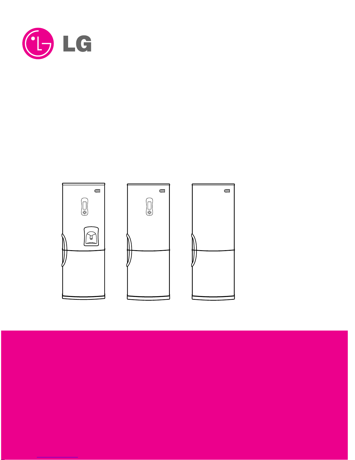
Features of refrigerant (R600a)
• Achromatic and odor less gas.
• Flammable gas and the ignition (explosion) at 494°C.
• Upper/lower explosion limit: 1.8%~8.4%/Vol.
Features of the R600a refrigerator
•
Charging of 60% refrigerant compared with a R134a model
•
The suction pressure is below 1bar (abs) during the operation.
• Because of its low suction pressure, the external air may
flow in the cycle system when the refrigerant leak, and it
causes malfunction in the compressor.
• The displacement of compressor using R600a must be at
least 1.7 times larger than that of R134a.
• Any type of dryer is applicable (XH-5, 7, 9).
• The EVAPORATOR or any other cycle part that has
welding joint is hidden in the foam. (If not hidden inside,
the whole electric parts must be tested with the
LEAKAGE TEST according to the IEC Standard.)
• The compressor has label of the refrigerant R600a.
• Only the SVC man must have an access to the system.
Installation place
• Must be well ventilated.
• Must be 20 m3or larger.
• Must be no-smoking area.
• No ignitable factors must be present.
Utilities
• Refrigerant cylinder (MAX NET 300g)
• Manometer
• Vacuum pump (600
L
/min)
• Piercing Clamp
• Quick coupler
• Hoses (5m-1EA, 1m-3EA)
• LOKRING
• Portable Leakage detector (3g/year↓)
• Nitrogen cylinder (for leakage test)
• Concentration gauge
Make sure before Servicing
• Refrigerant
Confirm the refrigerant by checking Name Plate and the label
on the compressor, after opening the COVER ASSY,
BACK-M/C.
• If the refrigerant is R600a, you must not weld or apply a
heat source.
Air Recharging in Compressor
Before refilling the refrigerant, you must perform the test according
to Chapter 5 (TROUBLESHOOTING CHART). When the defects
are found, you must discharge the residual refrigerant (R600a) in
the outdoor. For discharging the refrigerant R600a, break the
narrow portion of tube extension by hand or with a pipe cutter as
shown in Figure 1. Leave it for 30min in outside to stabilize the
pressure with ambient. Then, check the pressure by piercing the
dryer part with piercing pliers. If the refrigerant is not completely
discharged, let the refrigerator alone for more 30min in outside.
Attach the service tube installed with a Schrader valve (one-way
valve) by using the LOKRING (Figure 2). Then, connect the
Schrader valve (one-way valve) to the pump that is connected to
the discharging hose leading to the outside. When discharging the
residual refrigerant, repeat 3 cycle that includes 3min of the pump
running->pump off->30sec of the compressor running.
After the refrigerant (R600a) is completely discharged, repair any
defective parts and replace the dryer. At any case you must use the
LOKRING for connecting or replacing any part in the cycle (No Fire,
No Welding). Connect the Schrader valve to pump with the coupler.
And then turn the pump on for vacuum state (Figure 3). Let the
pump run until the low-pressure gauge indicates the vacuum (gauge
pressure 0, absolute pressure -1atm or -760mmHg). Recommended
vacuum time is 30 min. Charge the N2gas in order to check for
leakage from welding points and the LOKRING. If leakages are
found, repair the defects and repeat the vacuum process.
After the system is completely vacuumed, fill it with the refrigerant
R600a up to what has been specified at your refrigerator Name
Plate. The amount of refrigerant (R600a) must be precisely
measured within the error of ±2g by an electron scale (Figure 4).
If you use the manifold connected with both the refrigerant
(R600a) cylinder and the vacuum pump simultaneously,
make sure the pump valve is closed (Figure 5).
Connect the charging hose (that is connected to the refrigerant
(R600a) cylinder) to the Schrader valve installed on the service
tube. Then, charge the refrigerant (R600a) by controlling the
Throttle valve. When you do so, do not fully open the Throttle valve
because it may make damage to the compressor. Gradually charge
the refrigerant (R600a) by changing open and close the Throttle
Valve (5g at each time). The charging hose must use a one-way
valve to prevent the refrigerant refluence. Close the Schrader valve
cap after the refrigerant (R600a) is completely recharged.
After you completely recharge the refrigerant (R600a), perform the
leakage test by using a portable leakage detector or soapy water.
Test the low pressure (suction) parts in compressor off time and
high pressure parts in compressor on time. If the leakages are
found, restart from the refrigerant (R600a) discharging process and
repairs defects of leaks.
After the leakage test, check the temperature of each parts of the
cycle. Check with hands if the CONDENSER and the case (HOT-
LINE pipe) that is contacted to the door gasket are warm. Confirm
that frost is uniform distributed on the surface of the
EVAPORATOR.
TO THE
VACUUM
PUMP
PRESSURE
GAUGE
Figure 3
WEIGH SCALE
THROTTLE
VALVE
COUPLE
REFRIGERANT
(R600a) CHARGING HOSE
Figure 4
FILLING OR
CHARGE TUBE VALVE TO BE OPENED
WHEN REFILLING
VALVE TO BE CLOSED
AFTER VACUUM
TO THE VACUUM PUMP
TO THE
REFRIGERATION
SYSTEM
TO THE CHARGE
CYLINDER
Figure 5
SERVICING PRECAUTIONS
- 3 -
POINT TO BE
BROKEN CHARGE TUBE
EXTENSION
SCHRADER VALVE
(ONE-WAY VALVE)
LOKRING
SERVICE TUBE
EXTENSION
Figure 1 Figure 2

1. Ref. No: GR-459GK/QJ
SPECIFICATIONS
- 4 -
* Optional Parts
2. Ref. No: GR-459GR/QQ
ITEMS SPECIFICATIONS
DIMENSIONS (mm) 595(W)X665(D)X2000(H)
NET WEIGHT (kg) 85
COOLING SYSTEM Fan Cooling
TEMPERATURE CONTROL
Micom Control
DEFROSTING SYSTEM Full Automatic
Heater Defrost
DOOR FINISH Pre-Coated Metal or
Vinyl Coated Metal
OUT CASE Painted Steel Sheet
INNER CASE ABS
INSULATION Polyurethane Foam
DEFROSTING DEVICE
Heater, Sheath & Heater, Cord-L
REFRIGERANT R600a(60g)
LUBRICATION OIL FREOL S10(280 cc)
COMPRESSOR PTC Starting Type
EVAPORATOR Fin Tube Type
CONDENSER Wire Condenser
WATER DISPENSER Water Tank (1EA)*
ITEMS SPECIFICATIONS
REFRIGERATOR Transparent Shelf (2EA)
COMPARTMENT Folding Shelf (1EA)
Wine Rack (1EA)
Vegetable Container Cover (1EA)
Magic Crisper (1EA)
Vegetable Container (1EA)
Vegetable Container Divider (1EA)
Miracle Zone (1EA)
Deodorizer (1EA)
DOOR BASKET Dairy Basket (1EA)
Egg Tray (1EA)
Basket (2EA)
Moving Basket (1EA)
2lBottle Basket (1EA)
Bottle Guide (2EA or 0EA)
FREEZER Tray Drawer (3EA)
COMPARTMENT Twist Ice Tray (1EA)
Ice Bank (1EA)
Pizza Nook (2EA)
Nook Guide (1EA)
ITEMS SPECIFICATIONS
DIMENSIONS (mm) 595(W)X665(D)X2000(H)
NET WEIGHT (kg) 85
COOLING SYSTEM Fan Cooling
TEMPERATURE CONTROL
Micom Control
DEFROSTING SYSTEM Full Automatic
Heater Defrost
DOOR FINISH Pre-Coated Metal or
Vinyl Coated Metal
OUT CASE Painted Steel Sheet
INNER CASE ABS
INSULATION Polyurethane Foam
DEFROSTING DEVICE
Heater, Sheath & Heater, Cord-L
REFRIGERANT R600a(60g)
LUBRICATION OIL FREOL S10(280 cc)
COMPRESSOR PTC Starting Type
EVAPORATOR Fin Tube Type
CONDENSER Wire Condenser
WATER DISPENSER Water Tank (1EA)*
ITEMS SPECIFICATIONS
REFRIGERATOR Transparent Shelf (3EA or 2EA)
COMPARTMENT Folding Shelf (1EA)*
Wine Rack (1EA)*
Vegetable Container Cover (1EA)
Magic Crisper (1EA)*
Vegetable Container (1EA)
Vegetable Container Divider (1EA)*
Fresh Zone Container Cover (1EA)
Fresh Zone Container (1EA)
DOOR BASKET Dairy Basket (1EA)
Egg Tray (1EA)
Basket (2EA)
Moving Basket (1EA)
2lBottle Basket (1EA)
Bottle Guide (2EA or 0EA)
FREEZER Tray Drawer (3EA)
COMPARTMENT Twist Ice Tray (1EA)
Ice Bank (1EA)
Pizza Nook (2EA)
Nook Guide (1EA)
* Optional Parts

3. Ref. No: GR-459GC
- 5 -
ITEMS SPECIFICATIONS
DIMENSIONS (mm) 595(W)X665(D)X2000(H)
NET WEIGHT (kg) 85
COOLING SYSTEM Fan Cooling
TEMPERATURE CONTROL
Micom Control
DEFROSTING SYSTEM Full Automatic
Heater Defrost
DOOR FINISH Pre-Coated Metal or
Vinyl Coated Metal
OUT CASE Painted Steel Sheet
INNER CASE ABS
INSULATION Polyurethane Foam
DEFROSTING DEVICE
Heater, Sheath & Heater, Cord-L
REFRIGERANT R600a(60g)
LUBRICATION OIL FREOL S10(280 cc)
COMPRESSOR PTC Starting Type
EVAPORATOR Fin Tube Type
CONDENSER Wire Condenser
ITEMS SPECIFICATIONS
REFRIGERATOR Transparent Shelf (3EA)
COMPARTMENT Vegetable Container Cover (1EA)
Vegetable Container (1EA)
Fresh Zone Container Cover (1EA)
Fresh Zone Container (1EA)
DOOR BASKET Egg Tray (1EA)
Basket (3EA)
Moving Basket (1EA)
2lBottle Basket (1EA)
Bottle Guide (2EA)
FREEZER Tray Drawer (3EA)
COMPARTMENT Ice Tray (1EA)
Pizza Nook (2EA)
Nook Guide (1EA)
* Optional Parts

- 6 -
NOTE : This is a basic model. The shape of refrigerator is subject to change.
PARTS IDENTIFICATION
Dairy Corner
Door Basket
Moving Basket
Egg Tray
Door Basket
(Long or Half)
Water Tank
(Optional)
Utility Corner
(Pizza Nook)
Nook Guide
Removable
Glass Shelf
(2ea or 3ea)
Lamp
Wine Rack
(Optional)
Folding Shelf
(Optional)
Multi-air Flow Duct
Vegetable Drawer
Used to keep fruits
and vegetables, etc.
fresh and crisp.
Miracle Zone
(Optional)
Ice Tray
Ice Box
Freezer
Compartment
Removable
Plinth
Leveling Screw
2 Bottle
Door Basket
(Long or Half)
Handle
(user install)

This refrigerator allows the owner to change the door
swing if desired. The hinging of the doors can be changed
to the opposite side anytime you wish.
wwWarning Electric Shock Hazard
Disconnect electrical supply to refrigerator before installing.
Failure to do so could result in death or serious injury.
When reversing the door swing :
Read the instructions all the way through before starting.
• Handle parts carefully to avoid scratching paint.
• Set screws/bolts down by their related parts to avoid
using them in the wrong places.
• Provide a non-scratching work surface for the doors.
IMPORTANT
Once you begin, do not move the cabinet until door-swing
reversal is completed.
These instructions are for changing the hinges from the
right side to the left side-if you ever want to change the
hinges back to the right side, follow these same
instructions and reverse all references to left and right.
Before Removing the Doors, empty and Remove all the
Door Baskets of both Refrigerator/ Freezer Doors,
including the Bank Dairy. Close both doors before
removing hinge pins.
Caution :
Do not let either door drop to the floor. Doing so could
damage the Door Stop.
When reversing the door swing :
Read the instructions all the way through before starting.
• Handle parts carefully to avoid scratching paint.
• Set screws down by their related parts to avoid using
them in the wrong places.
• Provide a non-scratching work surface for the doors.
IMPORTANT
Once you begin, do not move the cabinet until door-swing
reversal is completed.
These instructions are for changing the hinges from the
right side to the left side-if
you ever want to change the hinges back to the right side,
follow these same
instructions and reverse all references to left and right.
wwWarning Electric Shock Hazard
Disconnect electrical supply to refrigerator before starting
the Door -reversal. Failure
to do so could result in death or serious injury.
Before Removing the Doors ,empty and Remove all the
Door Baskets of both Refrigerator/
Freezer Doors ,including the Bank Dairy. Close both doors
before removing hinge pins
Caution :
Do not let either door drop to the floor. Doing so could
damage the Door Stop.
INSTRUCTIONS FOR REVERSING DOOR SWING
- 7 -

1) Remove screws(3) after removing a CAP(2) from the
side of the refrigerator room HANDLE(1). Remove
screws(2) on the bottom of the refrigerator room
HANDLE(1). The freezer room HANDLE(5) may be also
disassembled in a same may as the refrigerator room
HANDLE(1).
2) Remove the screws(6) in the DECO COVER(7).
Remove the DECO COVER(7) and move the COVER
HINGE(8) to side of DECO COVER(7). Disassemble the
Housing Connector(9) inside of the DECO COVER(7).
3) Remove the screws(10) in the COVER-PWB(11), and
remove the COVER-PWB(11).
4) Remove the screws(12) in the TOP COVER FRONT(13)
and remove the TOP COVER FRONT (13).
5) Remove the HOLDER CORD (14) placed in right and
insert it to center. And then move COVER FRONT(16).
Take out the HOLDER CORD(spare) (15) and to place
in the center of TOP COVER FRONT(13), and insert to
the left side.
- 8 -
(2) (3)
(3)
(5)
(4)
(4)
(1)
(8)
(9)
(12)
(12)
(13)
(15)
(16)
(14)
(6)
(7)
(6)
(10)
(11)
(10)

6) Take out the LEAD WIRE(17) assembly from the TOP
COVER FRONT(13) and assemble it on left side.
7) Remove bolts(18) securing HINGE-U(19). Unscrew of
the hinge pin(20).
Place HINGE-U and seat hinge upside down and apply
them to left side of the refrigerator.
NOTE: Seat hinge to be placed under the HINGE-
U(19).
8) Remove bolts(22) securing HINGE-
C(23) and then remove HINGE-C(23).
Remove the freezer door. Move in left
side of the refrigerator CAP(24). Move
to left side of the refrigerator door
BRACKET DOOR(25) and screw(26).
9) Remove screws(27) and COVER(28)
and move CAP COVER(29).
And remove bolts(30), HINGE-L(31),
and move PIN(32).
10) Assemble the HINGE-L(31) ➝COVER(28) ➝Freezer Door ➝HINGE-C(23) ➝Refrigerator Door ➝HINGE-U(19) ➝
TOP COVER FRONT(13) ➝COVER PWB(11) ➝Connect the Housing Connector(9) ➝DECO COVER(7) ➝
HANDLE(1) (5)
Note:
Reversing the doors is not covered by the warranty.
- 9 -
(17)
(13)
(19)
(20)
(18)
(21)
(24)
(23)
(22)
(25)
(26)
(32)
(31)
(30)
(27)
(28)
(29)

- 10 -
1. DOOR
●Freezer Door
1) Refer to previous chapter "Instruction for Reversing
Door Swing".
2) Pull out the Door Gasket to remover from the
Door Foam Assy, F.
●Refrigerator Door
1) Refer to previous chapter "Instruction for Reversing
Door Swing".
2) Pull out the Door Gasket to remove from the
Door Foam Assy, R.
2. DOOR SWITCH
1) Unplug the power cord from the outlet.
2) Loosen five screws in upper part and disconnect Top
Cover Front.
3) Disconnect Lead Wire from switch.
4) Disengage hook behind the switch by pressing it with
hands.
3. REFRIGERATOR ROOM LAMP
1) Unplug the power cord from the outlet.
2) Remove the room lamp lid by taking down while pulling
its back projection.
3) Remove the lamp by turning it counterclockwise and
replace new one.
4) Assemble in reverse order of disassembly.
Replacement bulb must be the same specification as
original.
• You must check the O-RING, which is made by rubber
and prevent electric spark.
• Don’t touch the lamp, in case of light on the long time.
Because it can be very hot.
• Lamp capacity is MAX 30W.
• The lamp will remain “ON” for 7minutes if the door is left
open and then it is “OFF” for safety.
(If you reopen the door, the lamp is “On”.)
GASKET
Figure 7
Figure 9
DISASSEMBLY
Figure 10

- 11 -
4. FAN AND FAN MOTOR
1) Remove freezer drawers.
2) Remove two cap, screws and loosen two screws in
Grille Fan.
3) Pull out the Grille Fan and Shroud, F.
4) Disconnect the housing of lead wire.
5) Separate the Fan Assy.
6) Losse 2 screw fixed to the Bracket.
7) Pull out Shroud, F remove the Fan Motor Assy.
8) Separate the Motor Bracket and Rubber.
5. DEFROST CONTROL ASSY
Defrost Control Assy consists of Thermistor and Fuse,
Melting. Thermistor functions to defrost automatically and it
is attached to metal side of the Evaporator and senses
temperature.
Fuse, Melting is a kind of safety device for preventing
overheating of the Heater when defrosting.
At the temperature of 77°C, it stops the emission of heat
from the Heater.
1) Pull out the Shroud, F after removing the Grille.
2) Separate the connector connected with the Defrost
Control Assy and replace new one.
6. HEATER, SHEATH & HEATER, CORD-L
In this refrigerator, Heater, Sheath & Heater, Cord-L are
used for defrosting heater. During heating, the temperature
of heater rises about 300~350°C. Therefore, be careful not
to burn while servicing.
1) After removing the Grille and Shroud, separate the
Heater, Sheath by disconnecting the connectors.
2) Exchanged Heater, Sheath and connected the housing.
3) If the Heater, Cord-L is defected, disconnect the
connectors, and separate the Heater, Cord-L with
Long Nose.
4) Replace and assembly the Heater, Cord-L and connect
the connectors.
Heater, Sheath
Heater, Cord-L
GUIDE FANFAN
SHROUD
FAN MOTOR
GRILLE
Thermister
Fuse, Melting
Figure 13
Figure 11
Figure 12

ADJUSTMENT
- 12 -
1. COMPRESSOR
1) Role
The compressor intakes low temperature and low pressure
gas evaporated from Evaporator of the Refrigerator, and
condenses this gas to high temperature and high pressure
gas, and then plays delivering role to Condenser.
2) Composition
The Compressor is Composed of Compressor Apparatus
compressing gas, Compressor Motor moving Compressor
Apparatus and Case protecting Compressor Apparatus
and Motor. There is Relay Assy (one set of PTC-Starter
and Over Load Protector (OLP)) in Compressor. On the
other hand, because the Compressor consists of
1/1000mm processing precision components and is sealed
after production in absence of dust or humidity, deal and
repair with care.
3) Note for Usage
(1) Be careful not to allow over-voltage and over-current.
(2) No Strike
If applying forcible power or strike (dropping or careless
dealing), poor operation and noise may occur.
(3) Use proper electric components appropriate to the
Compressor.
(4) Note to Keep Compressor.
If Compressor gets wet in the rain and rust in the pin of
Hermetic Terminal, the result may be poor operation
and poor contact may cause.
(5) Be careful that dust, humidity, and flux welding don't
inflow in the Compressor inside in replacing the
Compressor. Dust, humidity, and flux due to welding
which inflows to Cylinder may cause lockage and noise.
2. PTC-STARTER
1) Composition of PTC-Starter
(1) PTC (Positive Temperature Coefficient) is a no-contact
semiconductor starting device which uses ceramic
material and this material consists of BaTiO3.
(2) The higher the temperature is, the higher becomes the
resistance value. These features are used as starting
device for the Motor.
2) Role of PTC-Starter
(1) PTC is attached to Hermetic Compressor used for
Refrigerator, Show Case and starts Motor.
(2) Compressor for household refrigerator applies to
single-phase induction Motor.
For normal operation of the single-phase induction
motor, in the starting operation flows in both main coil
and sub-coil. After the starting is over, the current in
subcoil is cut off. The proper features of PTC play all
the above roles. So, PTC is used as a motor starting
device.
3) PTC-Applied Circuit Diagram
●According to Starting Method for the Motor
4) Motor Restarting and PTC Cooling
(1) For restarting after power off during normal
Compressor Motor operation, plug the power cord after
5 min. for pressure balance of Refrigerating Cycle and
PTC cooling.
(2) During normal operation of the Compressor Motor, PTC
elements generate heat continuously. Therefore,
if PTC isn't cooled for a while after the power has been
shut off, Motor can't operate again.
5) Relation of PTC-Starter and OLP
(1) If the power is off during operation of Compressor and
the power is on before the PTC is cooled, (instant shut-
off within 2 min. or reconnect a power plug due to
misconnecting), the PTC isn't cooled and a resistance
value grows. As a result, current can't flow to the sub-
coil and the Motor can't operate and the OLP operates
by flowing over current in only in the main-coil.
(2) While the OLP repeats on and off operation about 3-5
times, PTC is cooled and Compressor Motor performs
normal operation.
If OLP doesn't operate when PTC is not cooled,
Compressor Motor is worn away and causes circuit-
short and fire. Therefore, use a properly fixed OLP
without fail.
6) Note to Use PTC-Starter
(1) Be careful not to allow over-voltage and over-current.
(2) No Strike
Don't apply a forcible power or strike.
(3) Keep apart from any liquid.
If liquid such as oil or water away enter the PTC,
PTC materials it may break due to insulation
breakdown of the material itself.
(4) Don't change PTC at your convenience.
Don't disassemble PTC and mold. If the exterior to the
PTC-starter is damaged, resistance value is altered and
it may cause poor starting of the compressor motor
may cause.
(5) Use a properly fixed PTC.
PTC STARTER HERMETIC
TERMINAL
COMPRESSOR
MOTOR
C
M
SM
3M
S
S
PTC
OVERLOAD
PROTECTOR(O.L.P)
RSIR
RELAY ASSY
Figure 19

- 13 -
3. OLP (OVER LOAD PROTECTOR)
1) Definition of OLP
(1) OLP (OVER LOAD PROTECTOR) is attached to the
Hermetic Compressor and protects the Motor by cutting
off current in Compressor Motor in case of over-rising
temperature by Bimetal in the OLP.
(2) When over-voltage flows to Compressor motor, the
Bimetal works by heating the heater inside the OLP,
and the OLP protects Motor by cutting off current which
flows to the Compressor Motor.
2) Role of the OLP
(1) The OLP is attached to the Hermetic Compressor used
for the Refrigerator and Show Case and prevents the
Motor Coil from being started in the Compressor.
(2) Do not turn the Adjust Screw of the OLP in any way for
normal operation of the OLP.
(Composition and connection Diagram of OLP)
CIRCUIT DIAGRAM
CONTACTING
POINT COVER
BIMETAL
CONTACTING
POINT
HEATER
TERMINALS
ADJUST
SCREW
HEATER
BIMETAL
Figure 20
NOTE : 1. This is a basic diagram and specifications vary in different localities.
uuBEST

- 14 -
uuBETTER
uuGOOD

1. COMPRESSOR AND ELECTRIC COMPONENTS
TROUBLESHOOTING (Mechanical Part)
- 15 -
1
2
3
4
5
2
5
5
3
4
5
5
1
43
YES
YES
NO
YES
YES
NO
NO
5
YES
NO
YES
Power
Source. Remove the Relay Assy
from the Compressor
and measure the voltage
between Terminal C of
Compressor and
Terminals M or S of
Relay Assy
No Voltage.
(Rating Voltage
±10%)?
Replace
Relay Assy
Replace
Relay Assy
O.K.
Advise the customer
to use a regular
Trans.
Replace Compressor.
OLP works within
30 sec. in forcible
OLP operation by
turning instant power
on and off.
Components start in
the voltage of Rating
Voltage ±10% below.
Applied voltage isn't
in the range of Rating
Voltage ±10%.
Check the resistance
among M-C, S-C and
M-S in Motor
Compressor.
Check the resistance of
two terminals in PTC-
Starter.
Check if applying
a regular OLP.
Measure minimum
starting voltage after 5
min. for balancing cycle
pressure and cooling the
PTC.
Check the
resistance of
Motor
Compressor.
Check the
resistance of
PTC-Starter.
Check OLP.
Check
starting state.

2. RELAY ASSY (PTC AND OLP)
- 16 -
LN
T
32
2
M
C
SM
C
S
YES
NO
Normal operation of
Compressor is
impossible or poor. Separate the Relay Assy
from Compressor and
measure the resistance
between M and S with a
Tester or Whistone Bridge.
(Figure 21)
Separate the Relay Assy
from the Compressor and
check the resistance value
between two terminals of
OLP with a Tester.
(Figure 22)
Observation value is
220V/50Hz : 22Ω±30%
115V/60Hz : 6.8Ω±30%
240V/50Hz : 33Ω±30%
127, 220V/60Hz :
22Ω±30%
The resistance value is 0
or serveral hundreds
Ω
.
The value is
∞
.
Check another
electric components.
Replace Relay Assy.
Check another
electric
components.
Replace
Relay Assy.
Figure 21 Figure 22

3. ANOTHER ELECTRIC COMPONENTS
- 17 -
▼Cooling is impossible
Compressor
doesn't run.
Running state of
Compressor is poor. Check a starting
voltage.
Check if current flows to
the following
components.
a. Thermistor
b. Starting devices
c. OLP
d. Compressor coil
e. Circuit Parts
Low voltage.
Poor contacting.
Shorted or broken.
Poor contacting
or shorted.
Coil shorted.
Poor contacting
or shorted.
Poor contacting
and broken.
Shorted.
Lack of capacity.
Coil of motor
Compressor. Replace
the compressor.
Replace
each component.
Raise the voltage.
Replace
each component.
Cause.
Check if current flows
to starting devices.
Check current flowing
in sub-coil of
Compressor.
Check capacity of OLP.
The items described
above are normal.
▼ Cooling ability is poor
Fan motor
doesn't run.
Much frost are sticked
to the EVAPORATOR.
Poor contacting.
Coil is shorted.
Shorted.
Replace
the Heater, Sheath
Replace
the Heater, Cord-L
Defect on
Heater, Cord-L
Replace
each component.
Replace
each component.
Check current flowing
in SWITCH, DOOR.
Check current flowing in the
MOTOR[MECH], FAN.
Check current flowing
of the following
components.
• THERMISTOR
• FUSE, MELTING
Check current flowing
of the following
components.
• HEATER, SHEATH
• HEATER, CORD-L

4. SERVICE DIAGNOSIS CHART
- 18 -
COMPLAINT POINTS TO BE CHECKED REMEDY
Cooling is • Is the power cord unplugged from the outlet? • Plug to the outlet.
impossible. • Check if the power switch is set to OFF. • Set the switch to ON.
• Check if the fuse of power switch is shorted. • Replace a regular fuse.
• Measure the voltage of power outlet. • If voltage is low, wire newly.
Cooling ability • Check if the set is placed close to wall. • Place the set with the space of about 10cm.
is poor. • Check if the set is placed close to stove, gas • Place the set apart from these heat
• cooker and direct rays. • appliances.
• Is the ambient temperature high or • Make the ambient temperature below.
• the room door closed?
• Check if put in is hot. • Put in foods after cooled down.
• Did you open the door of the set too often • Don't open the door too often and close
• or check if the door is closed up? • it firmly.
• Check if the Damper Control is set to "cold-position". • Set the control to mid-position.
Foods in the • Is foods placed in cooling air outlet? • Place foods in high temperature section.
Refrigerator • (Front Part)
are frozen. • Check if the control is set to "cold-position". • Set the control to "mid-position".
• Is the ambient temperature below 5°C? • Set the control to "warm-position".
Dew or ice • Is liquid food stored? • Seal up liquid foods with wrap.
forms in the • Check if put in is hot. • Put in foods after cooled down.
chamber of • Did you open the door of the set too • Don't open the door too often and close
the set. • often or check if the door is closed up. • it firmly.
Dew forms • Check if ambient temperature and humidity • Wipe dew with a dry cloth. This occurrence
in the Exterior Case. of surroumcling air are high. • is solved naturally in low temperature and humidity.
• Is there gap in the door packed? • Fill up the gap.
Abnormal • Are the set positioned in a firm and even place? • Adjust the Adjust Screw, and position
noise generates. • in the firm place.
• Are any unnecessary objects set • Remove the objects.
• in the back side of the set?
• Check if the Tray Drip is not firmly fixed. • Fix it firmly on the original position.
• Check if the cover of mechanical room • Place the cover at the original position.
• in below and front side is taken out.
To close the door • Check if the door packing is dirty • Clean the door packing.
is not handy. • with filth such as juice.
• Is the set positioned in a firm and even place? • Position in the firm place and adjust the
• Adjust Screw.
• Is too much food putted in the set? • Keep foods not to reach the door.
Ice and foods • Check if the inside of the set is dirty. • Clean the inside of the set.
smell unpleasant. • Did you keep smelly foods without wrapping? • Wrap smelly foods.
• It smells of plastic. • The new products smells of plastic, but it is
• eliminated after 1-2 weeks.
●In addition to the items described left, refer to the followings to solve the complaint.
Check if dew forms in
the Freezer.
Replace the
Components of
defrosting circuit.
Check Refrigerating
Cycle.
Check the
Damper Control
Defrosting
is poor.
The cycle
is faulty. Repair the cycle.
Replace the
Damper Control
The operation of
the Damper
Control is poor.

5. REFRIGERATING CYCLE
- 19 -
▼Troubleshooting Chart
▼Leakage Detection
● Observe discharging point of refrigerant which may be in the oil discharging part in the compressor and hole of evaporator.
YES
YES
Whether Compressor
runs or not.
Whether frost
forms or not in
Evaporator.
Observe the discharged
amount of Refrigerant.
Inject Refrigerant to Compressor
and check cooling operation.
Clogged by dust. Gas leakage.
Faulty
Compressor.
Moisture Clog.
Whether oil
leaks or not.
Frost formed normally
Normal amount
No or much amount
(Check the leakage point)
Frost formed normally
No frost
or forms
in inlet only
Check Compressor
PARTIAL Freezer room and Low flowing sound of A little high • A little Refrigerant
LEAKAGE Refrigerator Refrigerant is heard and more than • discharges.
don't cool frost forms in inlet only ambient • Normal cooling is possible
normally. temperature. • when injecting of Refrigerant
• the regular amount.
WHOLE Freezer room and Flowing sound of Refrigerant Equal to ambient • No discharging of Refrigerant.
LEAKAGE Refrigerator is not heard and frost isn't temperature. • Normal cooling is possible
don't cool formed. • when injecting of Refrigerant
normally. • the regular amount.
PARTIAL Freeze room and Flowing sound of Refrigerant A little high • Normal discharging of
CLOG Refrigerator is heard and frost forms more than • refrigerant.
don't cool in inlet only. ambient • The capillary tube is faulty.
normally. temperature.
WHOLE Freezer room and Flowing sound of Refrigerant Equal to ambient • Normal discharging of
CLOG Refrigerator is not heard and frost isn't temperature. • Refrigerant.
don't cool. formed.
MOISTURE Cooling operation Flowing sound of Refrigerant Low than • Cooling operation restarts
CLOG stops periodically. is not heard and frost melts. ambient • when heating the inlet of
temperature • capillary tube.
COMP- Freezer and Low flowing sound of A little high • The pressure of high
RESSION Refrigerator Refrigerant is heard and than ambient • pressure part in
don't cool. frost forms in inlet only. temperature. • compressor is low.
NO COMP- No compressing Flowing sound of Refrigerant Equal to ambient • No pressure of high pressure
RESSION operation. is not heard and no frost. temperature. • part in the compressor.
CAUSE TEMPERATURE
OF THE
COMPRESSOR REMARKS
STATE OF
THE SET STATE OF THE
EVAPORATOR
LEAKAGE
CLOGGED BY DUST
DEFECTIVE
COMPRESSION

- 20 -
NO. ITEMS CONTENTS AND SPECIFICATIONS REMARKS
WELDING (1) H 30
ROD (1) • Chemical Ingredients • Recommend H34 containing 34% Ag in the
(1) • Ag: 30%, Cu: 27%, Zn: 23%, Cd: 20% • Service Center.
(1) • Brazing Temperature: 710~840°C
(2) Bcup-2
(1) • Chemical Ingredients
(1) • Cu: About 93%
(1) • P: 6.8~7.5%
(1) • The rest: within 0.2%
(1) • Brazing Temperature: 735~840°C
FLUX (1) • Ingredients and how to make • Make amount for only day. (1)
(1) ••Borax 30% • Holding period: 1 day
(1) ••Borax 35% • Close the cover of container to prevent dust
(1) • Fluoridation kalium: 35% • putting in the FLUX.
(1) • Water: 4% • Keep it in a stainless steel container.
(1) • Mix the above ingredients and boil until
(1) • they are transformed into liquid.
LOKRING (1) Both of the tube is inserted up to the stop. • For a hermetically sealed metal/metal
(Figure 23,24) (2)
Both of the LOKRING is pushed up to the stop
connection, the tube ends have to be clean.
(3)
The bending point is not too close to the
• LOKPREP is distributed all of out-surface of
joint ending. • the tube ends.
(4) During the assembly it is important that
both ends remain completely within the
joint.
DRIER (1) Assemble the drier within 30min. • Don't keep the drier in a outdoors because
ASM (1) after unpacking. • humidity damages to it.
(2) Keep the unpacked drier at the temperature
of 80~100°C.
VACUUM (1) When measuring with pirant Vacuum • Apply M/C Vacuum Gauge without fail.
(1 )gauge the charging M/C, vacuum • Perform vacuum operation until a proper
(1 )degree is within 1 Torr. • vacuum degree is built up.
(2) If the vacuum degree of the cycle inside is • If a proper vacuum degree isn't built up,•
(2) 10 Torr. below for low pressure and 20 Torr. • check the leakage from
(2) for high pressure, it says no vacuum • the Cycle Pipe line part and
(2) leakage state. • Quick Coupler Connecting part.
(3) Vacuum degree of vacuum pump must be
(3) 0.05 Torr. below after 5 min.
(4) Vacuum degree must be same to the
value described item (2) above for more than
20 min.
(1) The pressure of dry air must be more
han 12~16kg/cm2
(2) Temperature must be more than
-20~-70°C.
(3) Keep the pressure at 12~6kg/cm2also
when substituting dry air for Nitrogen Gas.
NIPPLE (1) Check if gas leaks with soapy water. • Check if gas leaks from joint of the
AND (2) Replace Quick Coupler in case of leakage. • Coupler.
COUPLER
PIPE (1)• Put all Joint Pipes in a clean box and
(1)• cover tightly with the lid so that dust or
(1)• humidity is not inserted.
1
2
3
4
5
6
7
8
DRY AND
AIR
NITROGEN
GAS
▼General Control of Refrigerating Cycle
Table of contents
Other LG Refrigerator manuals

LG
LG LRBC20512 Series User manual

LG
LG LSC27931SB User manual

LG
LG GR-F218NI User manual

LG
LG GR-K30PS User manual

LG
LG SXS Refrigerator User manual

LG
LG LFXS27466 series User manual

LG
LG LSFD2491 series User manual

LG
LG LRSC21951 User manual

LG
LG LTC20380 Series Assembly instructions

LG
LG MFL68266707 User manual