LG LFC20770SB User manual

CAUTION
BEFORE SERVICING THE UNIT,
READ THE SAFETY PRECAUTIONS IN THIS MANUAL.
REFRIGERATOR
SERVICE MANUAL
MODELS:
LFC20770SB
LFC20770SW
LFC20770ST
LFC20786SW
LFC20786ST
LFC20786SB

CONTENTS
- 2 -
Please read the following instructions before servicing your
refrigerator.
1.Check the refrigerator for current leakage.
2.To preven telectric shock,unplug before servicing.
3.Always check line voltage and amperage.
4.Use standard electrical components.
5.Don't touch metal products in the freezer with wet
Hands.This may cause frost bite.
6.Prevent water from spiling on to electric elements or the
Machine parts.
7.Before tilting the refrigerator,remove all materials from
On or in the refrigerator.
8.When servicing the evaporator,wear gloves to prevent
Injuries from the sharp evaporator fins.
9.Service on the refrigerator should be performed by a
Qualified technician.Sealed system repair must be
Performed by a CFC certified technician.
SAFETY PRECAUTIONS
SAFETY PRECAUTIONS ........................................................................................................
1. SPECIFICATIONS ...............................................................................................................
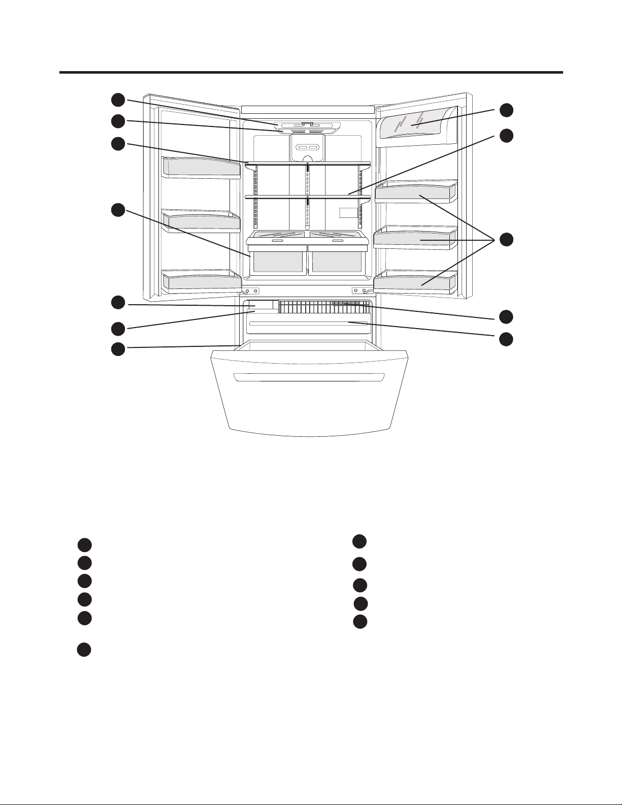
2. PARTS IDENTIFICATION ....................................................................................................
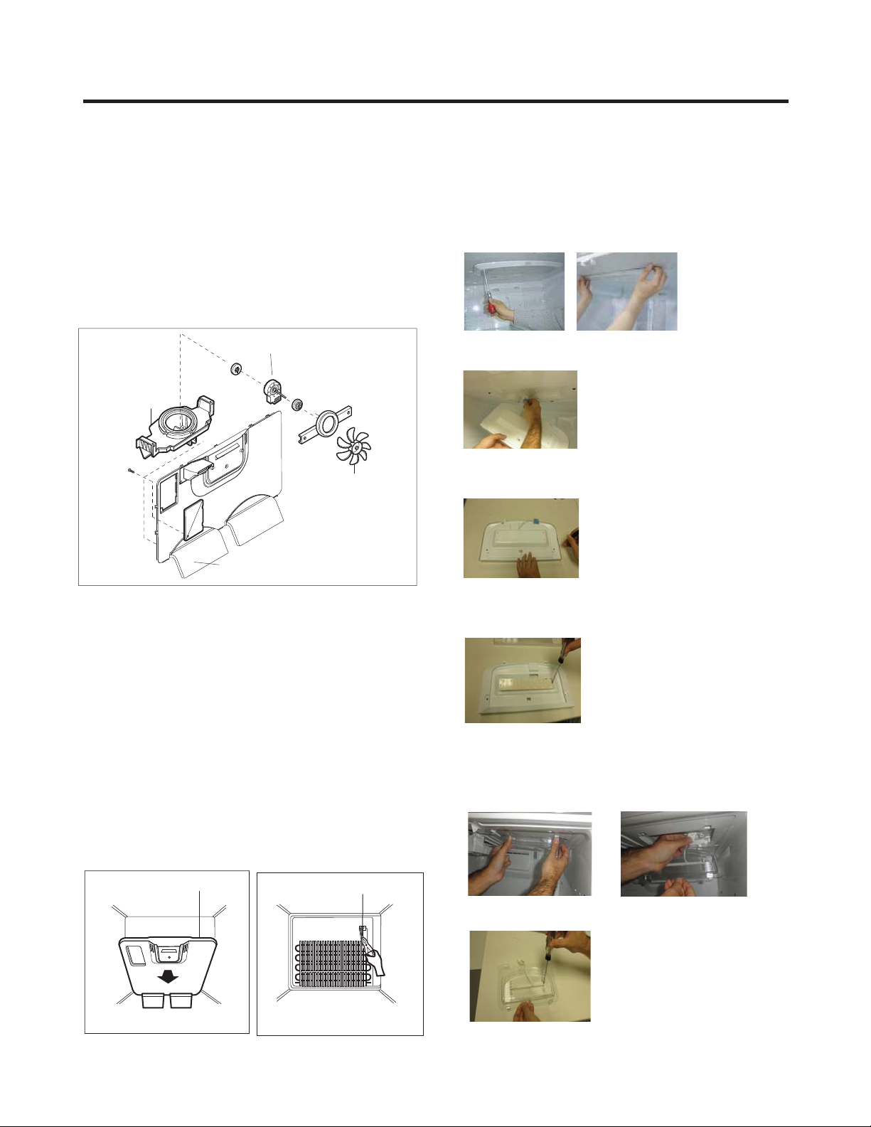
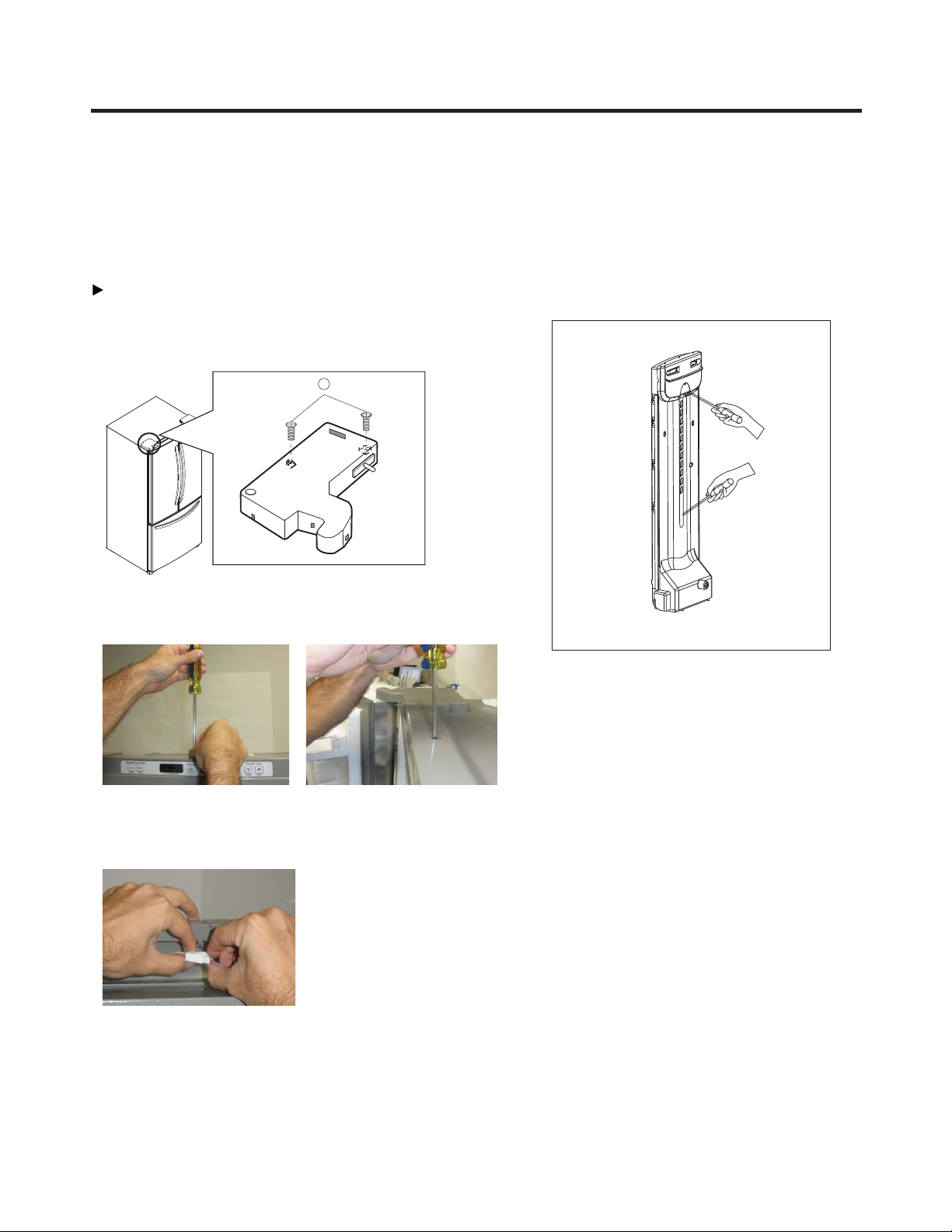
3. DISASSEMBLY ...................................................................................................................
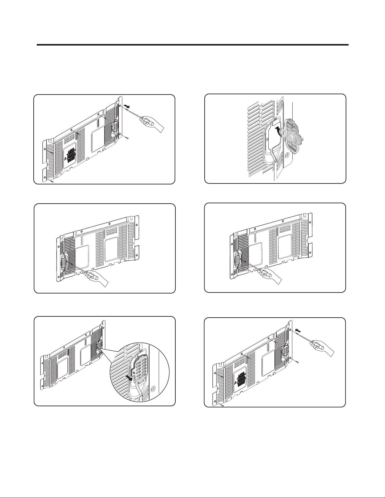
3-1 Fan and Fan Motor..........................................................................................................
3-2 Defrost Control Assembly.................................................................................................
3-3 LED................................................................................................................................
3-4 Display..................................................................................................
3-5 Multiduct..........................................................................................................................
3-6 Cover Valve......................................................................................................................
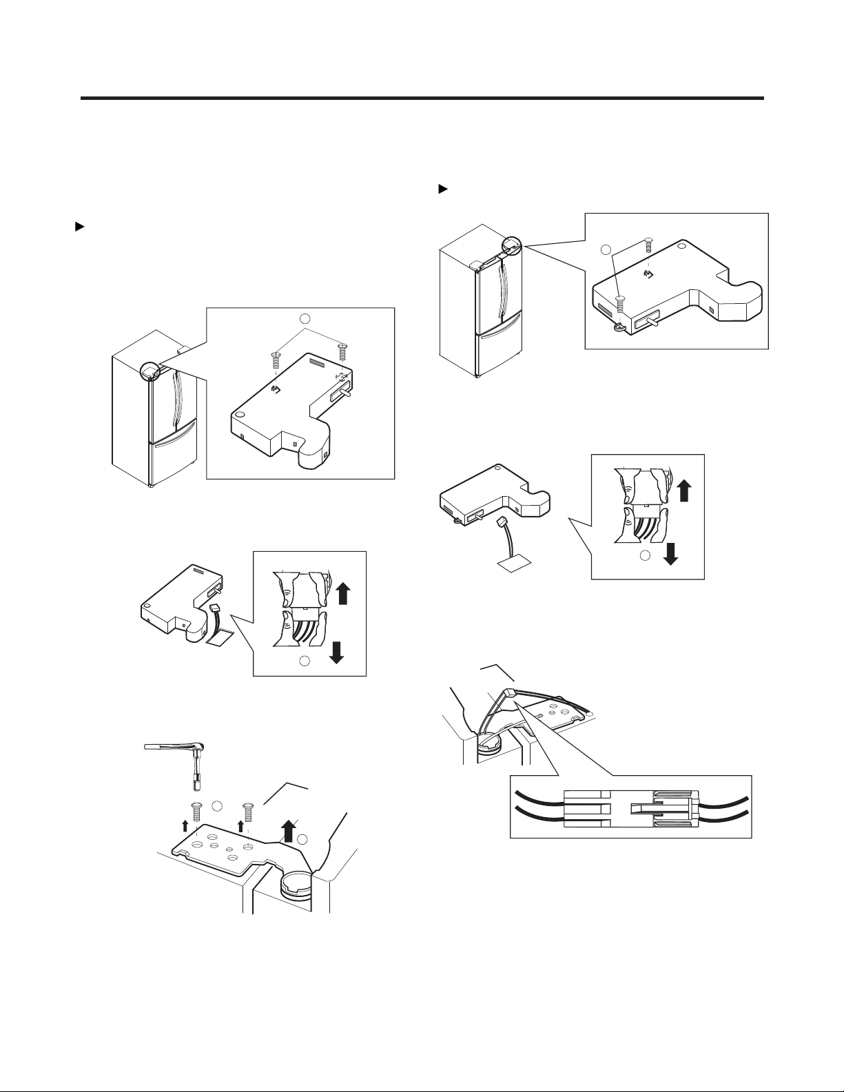
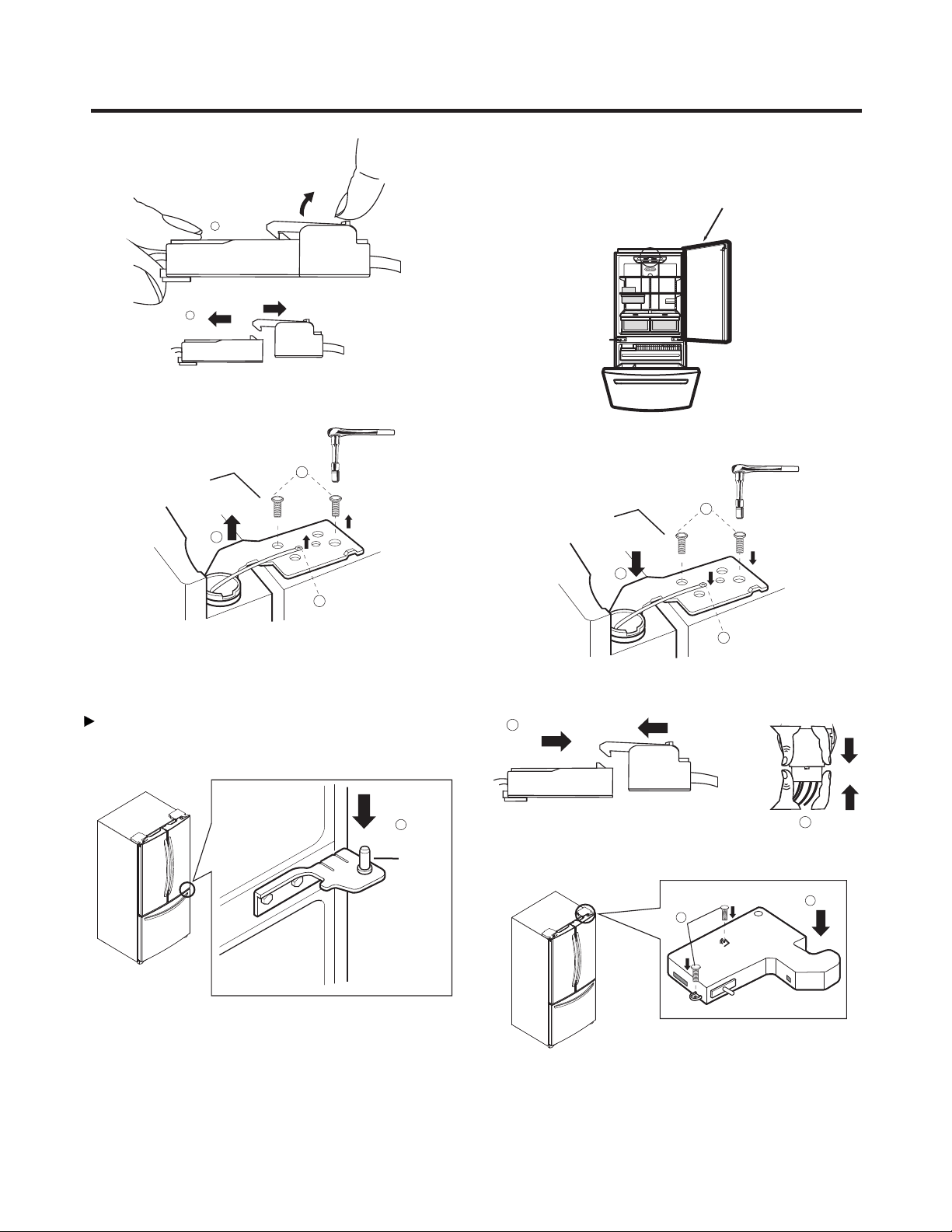
3-7 Door Disassembly............................................................................................................
3-8 How to remove the Door Handle.....................................................................................
3-10 How to remove Pull out drawer.....................................................................................
3-11 Closing and aligning the doors......................................................................................
4. ADJUSTMENT ...................................................................................................................
4-1 Compressor ...................................................................................................................
4-2 e-PTC-Starter ................................................................................................................
4-3 OLP (overload protector) ...............................................................................................
6. CIRCUIT DIAGRAM ............................................................................................................
8. TROUBLESHOOTING ........................................................................................................
8-1 Compressor and electric components ...........................................................................
8-2 e-PTC and OLP .............................................................................................................
8-3 Other electrical components ..........................................................................................
8-4 Service diagnosis chart ..................................................................................................
8-5 Refrigeration cycle .........................................................................................................
5. OPERATION PRINCIPLE AND REPAIR METHOD OF ICEMAKER ..................................
5.1 Operation principle .........................................................................................................
5.2 Ice maker functions ........................................................................................................
7. CIRCUIT OF MICOM............................................................................................................
7.1 Function .........................................................................................................................
7.2 PCB function ..................................................................................................................
9. EXPLODED VIEW ...............................................................................................................
2
3
4
5
5
5
5
6
6
7
8
10
12
13
16
16
16
17
27
27
28
29
30
31
18
18
19
24
24
26
33
3-9 How to remove the Pillar.................................................................................................
15
22
8-6 PCB Picture.......... .........................................................................................................
.................................................................................8.7 Troubleshooting With Error Display 37
............................................................................8.8 Troubleshooting Without Error Display 58
............................................................................8.9 Appendix.............................................. 81
86

1. SPECIFICATIONS
- 3 -
Color BLACK WHITE STAINLESS WHITE BLACK STAINLESS
Dimensions
Net Weight
Capacity
Refrigerant
Climate Class
Rated Rating
Cooling System
Temperature Control
Insulation
Compressor
Evaporator
Condenser
Lubricanting Oil
Drier
Capillary Tube
First Defrost
Defrost Cycle
Defrosting Device
Anti-freezing Heater
Case Material
Door material STAINLESS STAINLESS
Handle Type VISTA(AL) VISTA(AL)
Basket, Quantity
Ice Maker
Cover , T/V
Lamp
Shelf
Pantry
Tray,Egg
Basket, Quantity
Lamp
Tray, drawer F/L
Tray, drawer F/U
SPECIFICATIONS LFC20770SB LFC20770SW LFC20770ST
VISTA(Pl)
PCM
FREEZER
YES (FULL WIDTH)
GENERAL FEATURESREFRIGERATOR
3 LEFT+3 RIGHT
Defrosting System
2FIX (FULL)
INSTALLED READY [(1/B)+(2/T)
FAN COOLING
MICOM CONTROL
FULL AUTOMATIC
HEATER DEFROST
CYCLO PENTANANE
4 HOURS
7-40 HOURS
SHEATH HEATER
WATER TRANK HEATER
MQ53LAUM PTC STARTING TYPE
FIN TUBE TYPE
WIRE CONDENSER
POLYOL ESTER ISO 10 220+/-10cc
MOLECULAR SIEVE XH-7
TEMPERATURE (N)
115 V/60Hz
NO
YES(1) LED
YES (PLASTIC)
4EA(FIXED)
HUMIDITY CONTROL
YES(1) LED
YES
NO
PCM
VISTA(Pl)
3 LEFT+2 RIGHT
EMBO
ID Ø 0.75
MODELS
29.8(W) x 32.2(D) x 68.4(H) in
111 Kg
20 cu.ft.
R134A
LFC20786SW LFC20786SB LFC20786ST

DIMENSIONS
Depth w/ Handles
Depth w/o Handles
Depth w/o Door
Depth (Total with Door Open)
Height to Top of Case
Height to Top of Door Hinge
Width
Width (door open 90 deg. w/o handle)
Width (door open 90 deg. w/ handle)
A
B
C
D
E
F
G
H
I
Description
LFC20770**
28 ¼
38 ¼
33 ¼
32 ¼
44
29 ¾
34 ¾
67 716
68 316

2. PARTS IDENTIFICATION
- 4 -
Use this section to become more familiar with the parts and features.
NOTE: This guide covers several different models. The refrigerator you have purchased may have some
or all of the items listed below. The locations of the features shown below may not match your model.
* On some models
ADigital Sensor Control
Dairy Compartment*
Door Racks
Freezer Light
Pull Out Drawer
B
C
D
F
E
G
H
Durabase
I
J
K
Ice Bin
Optibin Crisper
Keeps fruits and vegetable fresh and crisper
Shelves
Refrigerator Light (Light Bulb or LED)
Ice Maker **
A
B
C
H
I
F
G
J
J
D
E
K
C
** Note: Some models do not include Ice Maker.
Ice Maker kit is available for sale.
(See about the Automatic Ice maker section)

GRILLE ASSEMBLY DEFROST-CONTROL
ASSEMBLY
GRILLE
FAN MOTOR
BRACKET
MOTOR
FAN
3-1 FAN AND FAN MOTOR
1. Remove the freezer shelf. (If your refrigerator has an
icemaker, remove the icemaker first).
2. Remove the plastic guide for slides on left side by
unscrewing phillips head screws.
3. Remove the grille by removing one screw and pulling the
grille forward.
4. Remove the Fan Motor assembly by loosening 2 screw and
disassemble the shroud.
5. Pull out the fan and separate the Fan Motor and Bracket.
3-2 DEFROST CONTROL ASSEMBLY
Defrost Control assembly consist of Drefrost Sensor and
FUSE-M.
The Defrost Sensor works to defrost automatically. It is
attached to the metal side of the Evaporator and senses its
temperature.
Fuse-M is safety device for preventing over-heating of the
Heater when defrosting.
At 72°C, it turns the Defrost Heater off.
1. Pull out the grille assembly. (Fig. 1)
2. Separate the connector with the Defrost Control assembly
and replace the Defrost Control assembly after cutting the Tie
Wrap. (Fig. 2)
3-3 LED
3-3-1 REFRIGERATOR COMPARTMENT LAMP
3-3-2 FREEZER COMPARTMENT LAMP
Fig. 1 Fig. 2
3. DISASSEMBLY
- 5 -
Unplug, or disconnect power at the circuit breaker.
If necessary, remove top shelf or shelves.
1)Release 2 screws.
2)Hold both ends and pull down to remove.
4)Use a flat tool as shown below to remove the lamp
cover.
5)To remove the LED assembly, pull apart the cover and
3) Remove LED connector
release the 2 screws.
1. Unplug refrigerator power cord form outlet.
2. Pull down the cover Lamp y r emove LED connector
3) Release 2 srews to remove LED.

3-5 MULTI DUCT
1. Remove an upper and lower Cap by using a flat
2. Disconnect the lead wire on the botton position.
- 6 -
3-4 DISPLAY
1. To disassemble, remove the cover hinge from any door.
IMPORTANT: Before you begin,
unplug your refrigerator.
Left Door
Release the two screws from
the upper lid (1) remove it after that.
1
2.Whit a screwdriver, remove the screw from Display.
3.Unplug the connector.
screwdriver, and loosen 2 screws.
NOTE: To assemble, follow the instruction above, at
inverse order.

3-6 VALVE COVER (in some models)
3-6-1 DISASSEMBLE 3-6-2 ASSEMBLE
1. Unscrew the back cover.
2. Unscrew the valve from the back side.cover
3. Push to the left and release.
1. Inserttheribstotherightsideoftheback holecover
2. Screwthe valve fromthebackside.cover
3. Screwthe back .cover
- 7 -

1. To remove Refrigerator door
3-7 DOOR DISASSEMBLY
IMPORTANT: Before you begin, turn the refrigerator OFF and
Unplug it. Remove all food and the shelves from the doors.
Left Door
Right Door
NOTE: The appearance of the handle might be different.
With the Philips screw driver, loose the two screws from
the upper lid (1) remove it after that.
1
2
With the 10mm socket wrench, loose the two pins from the
hinge (3) and remove it (4).
3
4
Unplug the switches cable (2) it’s optional, it’s no neccesary
do it for removing the door.
Place the door with the inner face over the surface so it
won't scratch.
5
Unplug the switches cable (6) it’s optional, it’s no
neccesary do it for removing the door.
6
Unplug the cable harness pulling up the hook located in
the upper part of it (7) and separate both parts of the
Upper view of
the harness
harness (8).
- 8 -

Loose the grounding screw (9) and the pins (10) located
over the hinge, after, lift the hinge and remove it (11).
8
Remove the door and place it over its inner face to avoid
scratching.
Right Door
Take the door and place it gently over the pin of the
1
Pin
Check that the sealing patch of the door is leveled to the
refrigerator and that it isn´t bended.
9
10
11
hinge (1).
7
Front view of
the harness
Place the hinge in its original position (4) assembly the
two pins (5) and the ground screws (6).
Plug the cable harness (7) and the switch (8) (just in case
7
8
4
5
6
Right Door
if you unplugged the switch).
Place the hinge lid (9) and install both screws (10). Be
sure the door is correctly assembled.
9
10
2. To install Refrigerator door
- 9 -

Take the left door and place it over the hinge (11).
Place the hinge in its original position (14) and place the
two screws (15).
Left Door
15
14
Be sure that the hook (12) located in the upper part of the
door) matches with the pillar of the refrigerator (13).
Check that the sealing patch of the door ends leveled with
the refrigerator and that it isn't bended.
11
Left Door
Plug the cable to the switch (16) (just in case if you
16
Place the hinge's lid (17) and screw the two screw (18).
Check that the door is well installed.
18
17
Loose the screws (1) with the Allen tool 3/32” and remove
the handle (2).
Remove the mounting screws with the ¼” Allen tool (3).
Mounting
Screws
Allen Wrench
Screws
1
2
3
unplugged the switch).
3-8 HOW TO REMOVE DOOR HANDLE
- 10 -

Install the mounting screws over the door (1) place the
1. To install the handle of the refrigerator
handle over them (2) and tight the screws up (3).
2. To remove the freezer's handle
With an 3/32” Allen tool, loose the screws (1) located on
from the door (3) with an ¼” Allen tool.
the bottom of the handle, remove it (2) remove the screws
Mounting
Screws
Screws
3
2
1
Wrench
Allen
3
2
1
3
3. To install the freezer's handle
Install the mounting screws over the door (1) place the
handle over them (2) and tight the screws up (3).
1
2
3
1
- 11 -

3-9 HOW TO REMOVE THE PILLAR
1. Remove the 2 screw with a screwdriver.
2. Pull up to get it out from the hook.the pillar
3. Unplug the connector to release the pillar..
NOTE: To assemble, follow the instruction above, at
inverse order.
- 12 -
IMPORTANT: Before you begin,
unplug your refrigerator.

3-10 HOW TO REMOVE PULL OUT DRAWER
IMPORTANT: To avoid possible injury or damage to the
product or your property, please use two people to perform
the following instructions:
1. Removing the Pull Out Drawer
•Pull the drawer out to maximum extension. Remove the
bottom rack (1) by tilting it back a little and then lifting it
•Remove the screws (3) from both sides of the rail track.
1
off the railing tracks.
3
CAUTION: When removing the drawer, do not hold the
handle. If it comes off, it could cause personal injury.
CAUTION: To place the drawer on the floor, take care
not to damage the floor or hurt your feet with the sharp
edges on the side with the hinges.
•With both hands, hold both sides of the door and pull up
to separate it.
•With both hands, hold the center of the bar and push it
in so that it is fit to both rails simultaneously.
2. Installing the Pull Out Drawer
•With both hands, hold the center of the bar and pull it
outward so that the two rails extend out at the same
time.
- 13 -

•Mount door supports (1) into the tabs on the railing
•Push the drawer down into position and tighten the
1
2
3
track (2), starting in the back first and then connecting
the part in the front last, as shown in the figure.
screws (3).
•With the drawer fully extended, insert the lower basket
over the front part of the rail assembly and then the
WARNING: To prevent entrapment risk and accidental
child or animal suffocation, DO NOT permit them to
play inside of the drawer.
WARNING: DO NOT step ot sit on the Freezer Door.
4
back part (4).
- 14 -

3-11 CLOSING AND ALIGNING THE DOORS
Open both doors again and check to make sure that
they close easily. If not, slightly tilt the refrigerator
further back by turning both leveling screws clockwise.
It may take several more turns. Make sure that you
turn both leveling screws the same amount.
Closing the Doors
Your refrigerator has two front leveling screws, one on the
right and one on the left. If your refrigerator seems
unstable or if you would like the doors to close more easily,
simply adjust the inclination of the refrigerator by following
1. Plug the refrigerator into a 3 prong grounded outlet.
Move the refrigerator into its final position.
2. Remove the base grille (Refer to the section on
“Installation of Base Grille”).
Use a flat head screwdriver to adjust the leveling
screws, turning clockwise to raise the side of the
refrigerator and counter-clockwise to lower it. It may
NOTE: Having someone push against the top of the
refrigerator takes some weight off the leveling screws.
This will make it easier to adjust the screws.
4.
5. Ensure that the refrigerator is even by using a level.
6. Replace the base grille.
the instructions below:
3.
take several turns to adjust it to the inclination you
would like.
Aligning the Doors
If the spacing between the doors is uneven, follow the
instructions below to align them:
1.
2.
3.
With one hand, lift up the door you want to raise at
middle hinge.
With other hand, use pliers to insert snap ring as
shown.
Insert additional snap rings until the doors are aligned.
(Three snap rings are provided per unit.)
- 15 -

4-1 COMPRESSOR
4-1-1 Role
The compressor intakes low temperature and low pressure
gas from the evaporator of the refrigerator and compresses
this gas to high-temperature and high-pressure gas. It then
delivers the gas to the condenser.
4-1-2 Composition
The compressor includes overload protection. The e-PTC
starter and OLP (overload protector) are attached to the
outside of the compressor. Since the compressor is
manufactured to tolerances of 1 micron and is hermetically
sealed in a dust and moisture-free environment, use
extreme caution when repairing it.
4-1-3 Note for Usage
(1) Be careful not to allow over-voltage and over-current.
(2) If compressor is dropped or handled carelessly, poor
operation and noise may result.
(3) Use proper electric components appropriate to the
Particular Compressor in your product.
(4) Keep Compressor dry.
If the Compressor gets wet (in the rain or a damp
environment) and rust forms in the pin of the Hermetic
Terminal, poor operation and contact may result.
(5) When replacing the Compressor, be careful that dust,
humidity, and soldering flux don’t contaminate the inside
of the compressor. Contamination in the cylinder may
cause noise, improper operation or even cause it to
lock up.
4-2 e-PTC-STARTER
4-2-1 Composition of PTC-Starter
(1) e-PTC (Positive Temperature Coefficient) is a no-contact
semiconductor starting device which uses ceramic
material consisting of BaTiO3.
(2) The higher the temperature is, the higher the resistance
value. These features are used as a starting device for
the Motor.
4-2-2 Role of PTC-Starter
(1) The e-PTC is attached to the Sealed Compressor and is
used for starting the Motor.
(2) The compressor is a single-phase induction motor.
Durign the starting operation, the e-PTC allows current
flow to both the start winding and main winding.
4-2-3 e-PTC-Applied Circuit Diagram
•Starting Method for the Motor
4-2-4 Motor Restarting and e-PTC Cooling
(1) It requires approximately 5 minutes for the pressure to
equalize before the compressor can restart.
(2) The e-PTC device generates heat during operation.
Therefore, it must be allowed to cool before the
compressor can restart.
4-2-5 Relation of e-PTC-Starter and OLP
(1) If the compressor attempts to restart before the e- PTC
device is cooled, the e-PTC device will allow current to
flow only to the main winding.
(2) The OLP will open because of the over current
condition. This same process will continue (3 to 5
times) when the compressor attempts to restart until
the e-PTC device has cooled. The correct OLP must be
properly attached to prevent damage to the
compressor.
Parts may appear physically identical but could have
different electrical ratings. Replace parts by part
number and model number. Using an incorrect part
could result in damage to the product, fire, injury, or
possibly death.
4-2-6 Note for Using the e-PTC-Starter
(1) Be careful not to allow over-voltage and over-current.
(2) Do not drop or handle carelessly.
(3) Keep away from any liquid.
If liquid such as oil or water enters the e- PTC,
e-PTC materials may fail due to breakdown of their
insulating capabilities.
(4) If the exterior of the e-PTC is damaged, the resistance
value may be altered. This can cause damage to the
compressor and result in a no-start or hard-to-start
condition.
(5) Always use the e-PTC designed for the compressor and
make sure it is properly attached to the compressor.
Parts may appear physically identical but could have
different electrical ratings. Replace parts by part
number and model number. Using an incorrect part
could result in damage to the product, fire, injury, or
possibly death.
4. ADJUSTMENT
PTC STARTER SEALED
TERMINAL
COMPRESSOR
MOTOR
C
M
SM
36
5
2
S
PTC
N
L1
OVERLOAD PROTECTOR
Resistance Starter Capacitor Running
C
- 16 -

4-3 OLP (OVERLOAD PROTECTOR)
4-3-1 Definition of OLP
(1) OLP (OVERLOAD PROTECTOR) is attached to the
Compressor and protects the Motor by opening the
circuit to the Motor if the temperature rises and
activating the bimetal spring in the OLP.
(2) When high current flows to the Compressor motor, the
Bimetal works by heating the heater inside the OLP,
and the OLP protects the Motor by cutting off the
current flowing to the Compressor Motor.
4-3-2 Role of the OLP
(1) The OLP is attached to the Sealed Compressor used
for the Refrigerator. It prevents the Motor Coil from
being started in the Compressor.
(2) For normal operation of the OLP, do not turn the Adjust
Screw of the OLP in any way.
Part
Customer part
number
Lot code/
date code
330 FBYY -S1 BOX98
12345678
termination
part number
Electrical
characteristics
part number
No. Name
Base, phenolic
(UL 94 V-0 rated)
Movable arm support,
Stationary contact support,
plated steel
Heater support, plated steel
Heater, resistance alloy
Disc, thermostatic alloy
Movable arm, spring temper
copper alloy
Contact, movable, silver on copper
Contact, stationary, silver on copper
Slug, plated steel
Cover, polyester
(UL 94 V-0 rated)
Pin connector, plated copper alloy
(To engage 2.33/2.66 mm dia. pin)
(OVERLOAD PROTECTOR cross section)
Fig. 2
Physical
plated steel.
- 17 -

5-1 OPERATION PRINCIPLE
5-1-1 Operation Principle of Icemaker
1. Turning the Icemaker stop switch off (O) stops the icemaking function.
2. Setting the Icemaker switch to OFF and then turning it back on will reset the icemaker control.
Initial Control
Icemaking
Control
Water supply control
TEST Control
Waits until water in the TRAY is frozen after Icemaker•
Starts operation.
• Runs MOTOR to drop ice from the tray into the ICE BIN.
• Performs Icemaking Mode after supplying water by operating
the SOLENOID in ICE VALVE.
• To operate LINE and SERVICE, press and hold the Fill Key
for 3 seconds. The icemaking will run through 3 stages:
Harvest Fill Icemaking.
Power Input
Adjusts Ejector to Start Position with power on.•
Ice Ejection
Control
Feeler Arm
Power Switch
Icemaker
5. OPERATION PRINCIPLE AND REPAIR METHOD OF
ICE MAKER
- 18 -

5-2 ICEMAKER FUNCTIONS
5-2-1 Start Position
5-2-2 Icemaking Mode
5-2-3 Ice Ejection Mode
1) When power is initially applied or reapplied after power is cut, it detects level of the TRAY after completion of MICOM
initialization. The detecting lever moves up and down.
2) The level of icemaker tray is judged by output signal, high and low signal, of HALL SENSOR. Make the tray to horizontal by
rotating ice ejection motor in normal or reverse direction so that High/Low signal can be applied to MICOM Pin (P22).
3) If there is no change in signals one minute after the geared motor starts to operate, it stops icemaker operation and check
the signal every hour. It resets initialization of icemaker when it becomes normal. Ice ejection conducts for 1 cycle.
a) Ice making control is carried out from the completion of water supply to the completion of ice making in the TRAY. Ice
making sensor detects the temperature of TRAY and completes ice making.(Ice making sensor is fixed below the TRAY.)
b) Ice making control starts after completion of water supply control or initial control.
Under the ice making control, the F room temperature should be operated with the NOTCH of “Normal/Strong”.
c) It is judged that ice making is completed when ice making sensor temperature reaches at -8ഒ after 70 minutes + 10
minutes when water is supplied to the TRAY.
a) This is to eject ice from the TRAY after ice making is completed.
b) If Hall IC signal is on within 3.6 seconds after ice ejection motor rotates in normal direction, it does not proceed ice ejection
but waits. If the ice bank is full, ice ejection motor rotates in normal direction in every hour to check the condition of ice bank.
If the ice bank is not full, the water supply control starts after completion of ice ejection control. If the ice bank is full, ice
ejection motor rotates in reverse direction and stops under ice making or waiting conditions.
c) If ice bank is not full, ice ejection starts. The TRAY tilts to the maximum and ice is separated from the TRAY and ice
checking lever raises.
d) Ice ejection motor stops for 1 second if Hall IC signal changes from OFF (low) to ON (high) after 3.6 seconds when ice
ejection motor rotates in normal direction. If there is no change in Hall IC signals within 1 minute after ice ejection motor
operates, ice ejection motor stops as ice ejection motor or hall IC is out of order.
e) If ice ejection motor or Hall IC is abnormal, ice ejection motor rotates in normal direction to exercise initial operation in
every hour. It resets the ice maker if ice ejection motor or Hall IC is normal.
f) The TRAY stops for 1 second at maximum tilted conditions.
g) The TRAY returns to horizontal conditions as ice ejection motor rotates in reverse direction.
h) When the TRAY becomes horizontal , the cycle starts to repeat.
Water Supply – Ice making – Ice ejection – TRAY returns to Horizontal.
- 19 -
Other manuals for LFC20770SB
4
This manual suits for next models
5
Table of contents
Other LG Refrigerator manuals

LG
LG LBNC12251V.APZCNA0 User manual

LG
LG LFC20745 Series User manual

LG
LG LMX25964 Series User manual

LG
LG GSL545NSQV User manual

LG
LG GL-B195OCOQ User manual

LG
LG LT18S2100 Series User manual

LG
LG LT1092BB Series User manual

LG
LG GF-D613SL User manual

LG
LG LFXS26566S User manual

LG
LG LSSB2691 series User manual