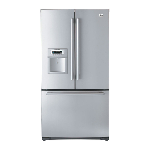
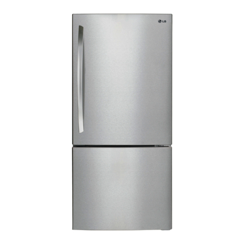
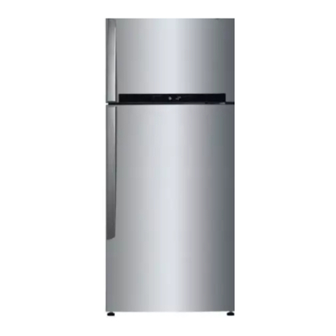
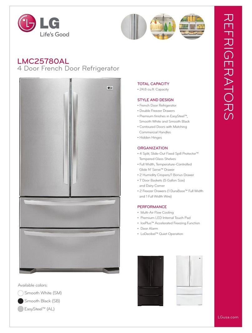
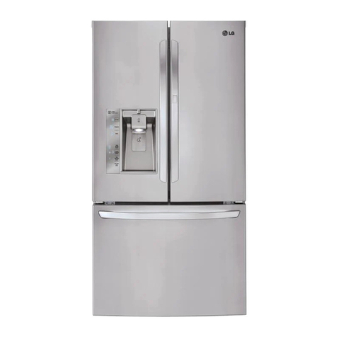
LG LFCC22426S User manual

CAUTION
BEFORE SERVICING THE UNIT,
READ THE SAFETY PRECAUTIONS IN THIS MANUAL.
REFRIGERATOR
SERVICE MANUAL
CONFIDENTIAL
Any reproduction, duplication, distribution (including by way of email, facsimile or other electronic means), publication,
modification, copying or transmission of this Service Manual is STRICT Y PROHIBITED unless you have obtained the prior
written consent of the LG Electronics entity from which you received this Service Manual. The material covered by this prohi-
bition includes, without limitation, any text, graphics or logos in this Service Manual.
Copyright © 2018-2019 LG Electronics Inc. All rights reserved. Only training and service purposes.
MODEL : LFCC22426S*

-2-
CONTENTS
SAFETY PRECAUTIONS .........................................................................................................................................2
1. SPECIFICATIONS ................................................................................................................................................3
2. PARTS IDENTIFICATION .....................................................................................................................................4
3. DISASSEMBLY................................................................................................................................................5-18
REMOVING AND REPLACING REFRIGERATOR DOORS ................................................................................................. 5
DOOR ..................................................................................................................................................................................... 6
SUB PCB ............................................................................................................................................................................... 7
FAN AND FAN MOTOR(EVAPORATOR) .............................................................................................................................. 8
DEFROST CONTROL ASSEMBLY ....................................................................................................................................... 9
LAMP....................................................................................................................................................................................... 9
MULTI DUCT ......................................................................................................................................................................... 9
MAIN PWB ............................................................................................................................................................................ 10
HOW TO REMOVE AND REINSTALL THE PULLOUT DRAWER ................................................................................. 11-12
WATER VALVE DISASSEMBLY METHOD ......................................................................................................................... 13
FAN AND FAN MOTOR DISASSEMBLY METHOD ............................................................................................................. 13
DRAWER REMOVAL .......................................................................................................................................................... 14
SAFETY PRECAUTIONS
Please read the following instructions before servicing your refrigerator.
1. Unplug the power before handling any elctrical componets.
2. Check the rated current, voltage, and capacity.
3. Take caution not to get water near any electrical components.
4. Use exact replacement parts.
5. Remove any objects from the top prior to tilting the product.
Copyright © 2019LG Electronics Inc. All rights reserved. Only training and service purposes.
Copyright © 2018-2019 LG Electronics Inc.All rights
reserved. Only training and service purposes.
DOOR ALIGNMENT ...............................................................................................................................................................8
CAP DUCT MOTOR REPLACEMENT ..................................................................................................................................10
4. ADJUSTMENT ....................................................................................................................................................16
5. CIRCUIT DIAGRAM ............................................................................................................................................17
6. TROUBLESHOOTING ........................................................................................................................................18
7. PCB PICTURE ...............................................................................................................................................20-23
8. TROUBLESHOOTING WITH ERROR DISPLAY ..........................................................................................24-68
9.
10.
REFERENCE .................................................................................................................................................69-72
11.
COMPONENT TESTING INFORMATION ...................................................................................................73-79
12.
COMPRESSOR TROUBLESHOOTING
......................................................................................................80-91
13.
ICEMAKER OPEARTING AND TROUBLE SHOOTING METHOD
............................................................92-95
DESCRIPTION OF FUNCTION & CIRCUIT OF MICOM ...........................................................................96-100
HOW TO REMOVE AND REFIT THE FRIDGE SHELF ...................................................................................................... 14
HOW TO REMOVE THE VEGETABLE DRAWER ............................................................................................................. 15
HOW TO REMOVE THE DOOR BASKET .......................................................................................................................... 15

-3-
1. SPECIFICATIONS
- 3 -
1. SPECIFICATIONS
ITEMS
1-1 LFCC22426S
ƽ 22.8 cu.ft.
ITEMS
Wire Condenser
R600a (56g)
LED Module
LED
SPECIFICATIONS
ƽDIMENSIONS
SPECIFICATIONS
Side Rounded
35 ¾ X 31 ¼ X 69 ¾ (WXDXH)
22.8cu.ft. 114kg (251lb)
Fan Cooling
Bar
ABS Resin
Polyurethane Foam
Clear Drawer Type
Linear
LFXC22526*
28 3/4''
(728 mm)
35 3/4"
(908 mm)
68 3/8"
(1737 mm)
69 3/4"
(1772 mm)
2"
(50 mm)
24 3/4''
(630 mm)
43 1/2''
(1103 mm)
24"
(610 mm)
31 1/4''
(792 mm)

-4-
2. PARTS IDENTIFICATION
- 4 -
LED Interior Lighting
Lights up the inside of the refrigerator.
Water filter
Purifies water.
Crisper
Helps vegetables and fruit to stay crisp.
Humidity Controlled Crisper
Helps vegetables and fruit to stay crisp and
controls humidity.
Fixed Door Bin
Stores chilled food or drinks.
Auto-Closing Hinge
Closes the refrigerator doors and freezer
drawers automatically.
2
3
4
5
Control Panel
Sets the refrigerator and freezer temperatures.
Adjustable Refrigerator Shelf
Adjustable shelves to meet individual storage
needs.
Glide‘N’Serve
Stores food items at a different temperature than
the regular refrigerator area.
Removable Ice Storage Bin
Stores ice produced by the icemaker.
Pullout Drawer
Provides extra storage within the freezer
compartment.
Durabase® and Durabase® Divider
Provides storage for large food items.
7
9
10
11
12
13
1
Automatic Icemaker (Freezer)
Produces and stores ice automatically in freezer
compartment.
6

-5-
3. DISASSEMBLY
3-1 Removing Refrigerator Door
CAUTION :
3. DISASSEMBLY
- 5-
●
Left Door -FIG. 1&2
1.Open door. Loosen top hinge cover screw (1).
Use flat tip screwdriver to pry back hooks on front underside of cover (2). Lift up cover.
2.Disconnect door switch wire harness and remove the cover.
3.Disconnect all wireharnesses (3). Remove the grounding screw (4).
4.Rotate hinge lever (5) counterclockwise. Lift top hinge (6) free of hinge lever latch (7).
5.Lift the left refrigerator door until it is free of the middle hinge assembly and remove door.
6.Place the door with the insides facing up, on a not scratch surface.
CAUTION: When lifting hinge free from the latch, be careful that door does not fall forward.
●
Right Door -FIG. 3&4
1. Open the door, Loosen top hinge cover screw (1). Lift up cover (2).
2. Disconnect all wire harnesses (3).
3. Remove the grounding screw (4)
4. Rotate hinge lever (5) clockwise. Lift top hinge (6) free of hinge lever latch (7).
5. Lift the right refrigerator door until it is free of the middle hinge assembly and remove door.
6.Place the door with the insides facing up, on a not scratch surface.
CAUTION: When lifting hinge free from the latch, be careful that the door does not fall forward.
Figure 1
Figure 2
(1)
(2)
(3)
(4)
(6) (7)
(5)
Figure 3
Figure 4
(1)
(2)
(3)
(4) (5)
(6)
(7)

-6-
- 6 -
1. Remove gasket
3-2 DOOR
Mullion Removal
1. Remove 2 screws.
Door Gasket Removal
2. Lift Mullion up carefully.
3. Disconnect wire harness.
Door Gasket Replacement
1. Insert gasket into channel
2. Insert mullion into the channel.
Mullion Replacement
1. Connect wire harness.
3. Assemble 2 screws.

-7-
- 6 -
1. Remove gasket
3-2 DOOR
Mullion Removal
1. Remove 2 screws.
Door Gasket Removal
2. Lift Mullion up carefully.
3. Disconnect wire harness.
Door Gasket Replacement
1. Insert gasket into channel
2. Insert mullion into the channel.
Mullion Replacement
1. Connect wire harness.
3. Assemble 2 screws.
Figure 1
Figure 2
Figure 3
Figure 4
Figure 5
Figure 6
Figure 7
Figure 8
-7-

-8-
- 8 -
3-4 Door Alignment 3-5 FAN AND FAN MOTOR(EVAPORATOR)
fl
* Ice Fan Assembly Replacement
Both the left and right refrigerator doors have an
adjustable nut, located on the bottom hinge, to raise
and lower them to align properly.
If the space between the doors is uneven, follow the
instructions below to align the doors evenly:
Use the wrench (included with the owner's manual)
to turn the nut in the door hinge to adjust the height.
Turn the nut to the right to raise the door or to the left
to lower it.
2) Pull off the sensor cover.
3) Remove the grill cover.
4) Gently pull on the grill assembly to remove.
5) Disconnect the wiring harness.
6) Remove all screws on the scroll assembly.
(1) (2)
(3) (4)
(5) (6)

-9-
- 8 -
˜
†
‘
’
€
•
‡†
‡‘ ‡’
‡€ ‡•
3-6 DEFROST CONTROL ASSEMBLY
Figure 12 Figure 13
3-4 Door Alignment
3-5 FAN AND FAN MOTOR(EVAPORATOR)
⁄fl‹f
Figure 9
Figure 10
Figure 11
- 9 -
3-7-2 Cap Decor LED LAMP(Bottom)
7RUHPRYHWKH/('DVVHPEO\
/('$VVHPEO\
5HPRYHWKHVFUHZDWWKH
&HQWHURI'XFW0XOWL
5HPRYHWKHVFUHZDQG
FRYHUILOWHU
'LVFRQQHFWWKHOHDGZLUH
RQWKHERWWRPSRVLWLRQ
3-6 DEFROST CONTROL ASSEMBLY
3-7 Lamp
3-7-1 Refrigerator Compartment Lamp
1) Pull out cover lamp as using sharp-edged tool.
Unplug, or disconnect power at the circuit breaker.
If necessary, remove top shelf or shelves.
Defrost Control assembly consists of Defrost Sensor and
FUSE-M.
The Defrost Sensor works to defrost automatically. It is
attachd to the metal side of the Evaporator and senses its
temperature. At 46℉(8℃), it turns the Defrost Heater off.
FUSE-M is a safety device for preventing over-heating of
the Heater when defrosting.
1. Pull out the grille assembly.
2. Separate the connector with the Defrost Control
assembly and replace the Defrost Control assembly after
cutting the Tie Wrap.
3Decor Duct(Grille) SVC.
Remove the Decor Duct with tools like flat-head
screwdriver.
3-8 Multi Duct
1. Unplug refrigerator power cord from electric outlet.
2. Open the refrigerator door to need diassembly.
3. Put flat screwdriver into service hole, remove the cover
of cap decor LED LAMP.
5. Replace LED assembly.
6. Assembly the cover in reverse order.
4. Remove the LED assembly from connector.

-10-
- 1 0 -
3-9 MAIN PWB
1) Loosen 3 screws on the PWB cover.
2) Remove the PWB cover.
3) Disconnect wire harness and replace the main PWB
in the reverse order of removal.
3-10 CAP DUCT MOTOR REPLACEMENT
1) Separate the Housing of the Cap Duct Motor.
2) Unscrew 3 screws to disassemble the motor.
5) Push housing aside.

-11-
- 14 -
3-11 HOW TO REMOVE AND REINSTALL THE PULLOUT DRAWER
3-11-1 Follow Steps to Remove
Step1)
Step 3) Remove the two screws from the guide rails.
(one from each side)
Step 5) Remove only 1 screw of gear ice, and disassemble
the bar and gear ice.
Step 4) Removal of the freezer door is done by lifting clear
of the rail support.
Fully extend both rails.
Step 6) Remove 2 screws of both side of supporter cover TV
and disassembly the supporter cover TV.

-12-
- 14 -
3-19 HOW TO REMOVE AND REINSTALL THE PULLOUT DRAWER
3-19-1 Follow Steps to Remove
˜°˛˝˙ˆˇ
˜°˛˝˙†ˇ
˜°˛˝˙šˇ
˜°˛˝˙€ˇ
- 15 -
3-11-2 Follow Steps to Reinstall
Step 1) cover TV into
Step 6) Reinstall the freezer door by inserting the rails tabs
Step 8) Reinstall the lower basket, and close the freezer
Step 5) The rail system will align itself by pushing the rails
Step 7) Reinstall the two screws into the guide rails.
Step 2) ķ Assemble a bar and gear ice with screw
ĸ

-13-
- 16 -
3-12 WATER VALVE DISASSEMBLY METHOD
1) l
housing and remove the valve.
Figure 62
Figure 63
3-13 FAN MOTOR ASSEMBLY AND
DISASSMEMBLY METHOD
1) Remove screws for the Drain Pipe Assembly and the 1
connected to the Motor Cover.
2) Remove the screw from shroud and Separate the Fan
motor assembly and Shroud.
Assemble in reverse order. Taking care to avoid.
1. Do not to bend the tube during assembly.
2. Press the Water Dispenser button letting water pour out,
this checks for any leaks in the tube connection, this may
vary depending on the water pressure
( about 2 minutes.).

-14-
- 16 -
3-21 WATER VALVE DISASSEMBLY METHOD
˜°
Figure 60
Figure 61
Figure 62
Figure 63
3-22
- 17 -
3-14 DRAWER REMOVAL
1) Pull the drawer open to full extension.
2) Gently lift and pull out the ice bin.
3) Lift the front of the drawer up,
then pull it straight out.
4) Remove the Durebase basket from the rails.
Remove the screws from the rails at both ends.
5) Grip both sides of the drawer and pull it up to
remove it from the rails.
3-15 HOW TO REMOVE AND REFIT THE FRIDGE SHELF
3-15-1 Removing the Fridge Shelf
1) Tilt the front of the shelf up and then lift the shelf straight up.
2) Lower the front of the shelf so that the hooks into the holes.
3-15-2 Refitting the Fridge Shelf
1) Tilt the front of the shelf up and guide the shel
hooks into the holes at the desired height.
2) Lower the front of the shelf so that the hooks into the holes.

3-16 HOW TO REMOVE THE VEGETABLE DRAWER
1) Remove the contents of the drawer.
Holde the handle of the drawer and gently
pull it out completely until it stops.
2) Lift the vegetable drawer up and remove it by pulling it out.
3) Repeat to remove the second drawer.
4) Tilt the cover slightly and support it with both hands
while pulling it out.h
3-17 HOW TO REMOVE THE DOOR BASKET
1) To remove the basket, simply lift the bin up
and pull straight out.
2) To replace the basket, slide it in above
the desired support and push down until
it snaps into place.
-15-

-19-
4. ADJUSTMENT
- 19 -
4-2-3 Compressor protection logic
4. ADJUSTMENT
4-1-1 Role
4-1 COMPRESSOR
4-1-2 Note for Usage
4-1-3 Remove the cover PTC
(1) Remove the Cover Back M/C
(2) Loosen two screws on comp base
(3) Use a L-shaped flap tooll to pry off the cover
(4) Assembly in reverse order of disassembly
(1) Be careful not to allow over-voltage and over-current.
(2) Do not drop or handle carelessly.
(3) Keep away from any liquid.
If liquid such as oil or water enters the Cover PTC
Compressor may fail due to breakdown of their
insulating capabilities.
(4) Always use the Parts designed for the compressor and
make sure it is properly attached to the compressor.
Parts may appear physically identical but could have
different electrical ratings. Replace parts by part number
and model number. Use only approved substitute parts.

-20-
5. CIRCUIT DIAGRAM
- 20 -
5. CIRCUIT DIAGRAM
MEZ66414026 (Label,Circuit)

-21-
6. TROUBLESHOOTING
- 20 -
5. CIRCUIT DIAGRAM
ᢶᵥ㾷≸φ
দᓊᲦθᰖ⊗⛯দⰋ䘯ㅿ㕰䲭χ
দ仒㢨Ѱ唇㢨3$1721*&χ
ᶆᯏѰJ䬒⡾㓮у䖢〱уᒨ㜬χ
ཌṼ㓵Ѱ࠽ࢨ㓵χ
䜞ᗻ䴶уᴿ⾷↘⢟䍞ྸφ3E&G+J&U3%%3%'(
ᒬъ㾷ᇂޞㅜ/*$ะȾ
MEZ66414011 (Label,Circuit)
˜
°
˛
˝
˙
ˆ
ˇ
˘
˜˜
˜°
˜˛
˜˝
˜˙
˜ˆ
˜ˇ
˜˘
°˜
°°
7
YL/WH
BN YL
WATER PIPE HEATER
1
RD/
WH BL/
WH
2
CON103
CON802
4
PK
BO
SB
WH
3
2
1
WI-FI
MODEM
BK RD
chauffage à l'eau
MEZ66414011
- 21 -
6. TROUBLESHOOTING
6-1 Error Code Summary
WARNING:
NOTE)
NO Error Detection
Category
—
⁄
š
š
š
š
š
š
š
š
š
š
š
•
Error Generation Factors Remark
Error Display
−
‰
„
—”
‚
Š
——
—⁄
—−
‹f
ł
Freezer
Refrigerator
Temperature
(Error code
ķ)
Temperature
(Error code ĸ)

-22-
7. PCB Picture
7. PCB Picture
( P/N : EBR841464**)
7-1. Main PCB
7-2. Display PCB
( P/N : EBR838450**)
CON4
CON102
CON101
CON103
CON802
CON1
CON201
CON5
CON7
CON2 CON3

-24-
8. Trouble Shooting
8. Trouble Shooting
Symptom Check Point
1. FS E 1. Check for a loose connection
2. Check Sensor Resistance
8-1. Freezer Sensor Error (FS E)
Resistance [Ω]
CON7
17th pin ~ 20th pin
Short 0
Open OFF
Other Normal
CON7
17th pin ~ 20th pin Resistance [Ω]
-22ºF / -30ºC 40k
-13ºF / -25ºC 30k
-4ºF / -20ºC 23k
5ºF / -15ºC 17k
14ºF / -10ºC 13k
23ºF / -5ºC 10k
32ºF / 0ºC 8k
CON1
CON201
CON4
CON5
CON7
CON2 CON3
Table of contents
Other LG Refrigerator manuals

LG
LG LS66SXNC User manual

LG
LG GR-V323 S User manual

LG
LG LSC 21943ST User manual

LG
LG GR-D24 Series User manual

LG
LG LFXS24623S User manual

LG
LG GM-769RC User manual

LG
LG Kimchi GR-K24PS User manual

LG
LG LFX25975SW - 24.7 cu. ft. Refrigerator User manual

LG
LG LRTLS2403S / 00 User manual

LG
LG LSXS26396S User manual