LG LMX21981** /01 User manual

CAUTION
BEFORE SERVICING THE UNIT,
READ THE SAFETY PRECAUTIONS IN THIS MANUAL.
REFRIGERATOR
SERVICE MANUAL
COLOR: STAINLESS(ST)
SUPER WHITE(SW)
WESTERN BLACK(SB)
MODEL: LMX21981** /01
LMX25981** /01
www.Appliantology.org

E C N (E ngineering C hange Number)
410G
304A
616J
317A
303B
303C
230B
230A
231B
231A
500A
616H
329D
243B
243A
300A
L oc No.
C apacitor,E lectric Appliance F ilm,B ox
C over,P T C
C onnector,T ube
Drier As sembly
T hermistor As sembly,P T C
Overload P rotect
Door Assembly,R efrigerator(Left)
Door Assembly,R efrigerator(R ight)
Door F oa m As sembly,R efrigerator
P C B As sembly
C onnector,T ube
G uide,Air
S topper,Door
S topper,Door
C omressor,S et
P art Name
LMX25981
/01
www.Appliantology.org

SAFETY PRECAUTIONS....................................................................................................................................................... 2
1. SPECIFICATIONS............................................................................................................................................................... 3
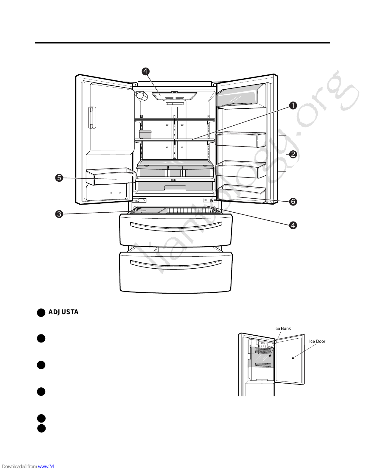
2. PARTS IDENTIFICATION................................................................................................................................................... 4
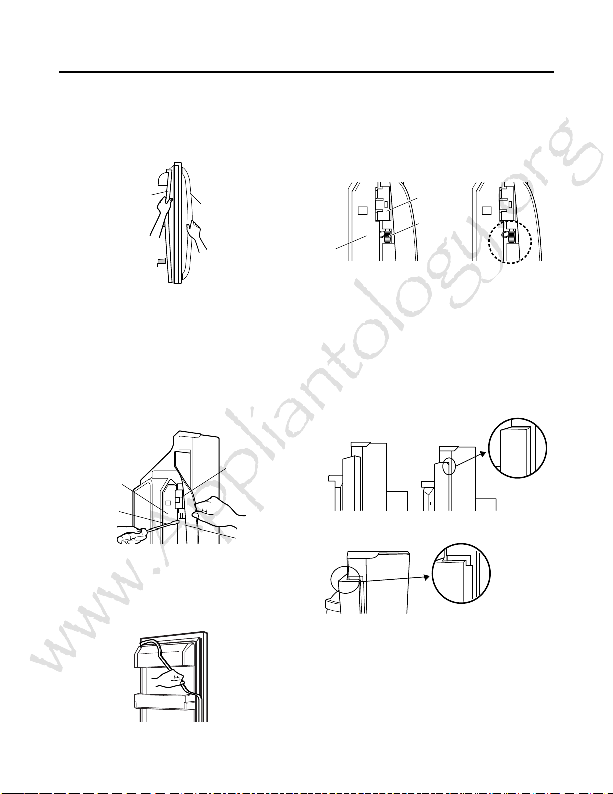
3. DISASSEMBLY.............................................................................................................................................................. 5-14
REMOVING AND REPLACING REFRIGERATOR DOORS ...............................................................................................5
DOOR INSTALLATION....................................................................................................................................................... 6
DOOR.............................................................................................................................................................................. 7-8
TO REMOVE THE DISPENSER .........................................................................................................................................8
DOOR ALIGNMENT............................................................................................................................................................8
FAN AND FAN MOTOR(Evaporator).................................................................................................................................. 8
ICE FAN SCROLL ASSEMBLY REPLACEMENT ..............................................................................................................9
DEFROST CONTROL ASSEMBLY.................................................................................................................................... 9
LAMP.................................................................................................................................................................................. 9
CONTROL BOX-REFRIGERATOR .................................................................................................................................... 9
MULTI DUCT .................................................................................................................................................................... 10
MAIN PWB, DISPLAY PWB REPLACEMENT, FUNNEL REPLACEMENT......................................................................10
SUB PWB FOR DISPENSER, DUCT DOOR REPLACEMENT, ICE CORNER DOOR
REPLACEMENT, ICE MAKER ASSEMBLY.......................................................................................................................11
AUGER MOTOR COVER, AUGER MOTOR REPLACEMENT.........................................................................................12
DOOR ICE BIN..................................................................................................................................................................13
HOW TO REMOVE AND REINSTALL THE PULLOUT DRAWER...............................................................................14-17
4. ADJUSTMENT............................................................................................................................................................. 18-19
COMPRESSOR................................................................................................................................................................ 18
PTC-STARTER................................................................................................................................................................. 18
OLP(OVERLOAD PROTECTOR)......................................................................................................................................19
TO REMOVE THE COVER PTC.......................................................................................................................................19
5. CIRCUIT DIAGRAM.......................................................................................................................................................... 20
6. TROUBLESHOOTING................................................................................................................................................. 21-25
COMPRESSOR AND ELECTRIC COMPONENTS.......................................................................................................... 21
OTHER ELECTRICAL COMPONENTS ........................................................................................................................... 22
SERVICE DIAGNOSIS CHART........................................................................................................................................ 23
REFRIGERATION CYCLE .......................................................................................................................................... 24-25
7. OPERATION PRINCIPLE & REPAIR METHOD OF ICEMAKER .............................................................................. 26-28
8. DESCRIPTION OF FUNCTION, CIRCUITS & ERROR CODES..................................................................................29-45
9. EXPLODED VIEW & REPLACEMENT PARTS LIST ..................................................................................................... 46-
CONTENTS
- 2 -
Please read the following instructions before servicing your
refrigerator.
1. Unplug the power before handling any elctrical
componets.
2. Check the rated current, voltage, and capacity.
3. Take caution not to get water near any electrical
components.
4. Use exact replacement parts.
5. Remove any objects from the top prior to tilting the
product.
SAFETY PRECAUTIONS
www.Appliantology.org

21 cu. ft. / 025 cu. ft
1. SPECIFICATIONS
- 3 -
ITEMS SPECIFICATIONS
DOOR DESIGN Side Rounded
DIMENSIONS (inches)
35 3/4X 30 1/4X 69 3/4(WXDXH) 21cu.ft
35 3/4X 34 1/4X 69 3/4(WXDXH) 21cu.ft
NET WEIGHT (pounds) 302.58 (
21cu.ft)
324.18 (
25cu.ft)
COOLING SYSTEM Fan Cooling
TEMPERATURE CONTROL Micom Control
Full Automatic
DEFROSTING SYSTEM Heater Defrost
DOOR FINISH Embossed Metal, VCM, Stainless
HANDLE TYPE Bar
INNER CASE ABS Resin
INSULATION Polyurethane Foam
ITEMS SPECIFICATIONS
VEGETABLE TRAY Opaque Drawer Type
COMPRESSOR Recipro
EVAPORATOR Fin Tube Type
CONDENSER Wire Condenser
REFRIGERANT R-134a (140 g)
LUBRICATING OIL ISO10 (280 ml)
DEFROSTING DEVICE SHEATH HEATER
LAMP REFRIGERATOR LED Module(27)
FREEZER LED Module(9)
Description LMX21981** /01 LMX25981** /01
Depth w/ Handles A 30 in. 34 1/4 in.
Depth w/o Handles B 27 1/2 in. 31 1/4 in.
Depth w/o Door C 23 5/8 in. 27 7/8 in.
Depth (Total with Door Open) D 42 1/4 in. 46 1/2 in.
Height to Top of Case E 68 3/8 in. 68 3/8 in.
Height to Top of Door Hinge F 69 3/4 in. 69 3/4 in.
Width G 35 3/4 in. 35 3/4 in.
Width (door open 90 deg. w/o handle) H 39 1/4 in. 39 1/4 in.
Width (door open 90 deg. w/ handle) I 44 1/4 in. 44 1/4 in.
DIMENSIONS
www.Appliantology.org

2. PARTS IDENTIFICATION
- 4 -
3
5
4
6
1
2
4
ADJUSTABLE REFRIGERATOR SHELVING
The refrigerator compartment shelves are adjustable to
allow flexibility for storage needs.
MODULAR DOOR BINS
Three interchangeable bins can be arranged to suit your
storage needs.
REMOVABLE ICE STORAGE BIN
The ice storage bin can be removed to fill ice
buckets,coolers,or pitchers.
INTERIOR LAMPS
Two separate LED arrays light the freezer and refrigerator
interiors.
FIXED DOOR BIN
FIXED DOOR BIN
1
2
3
4
5
6
Ice Bank
Ice Door
www.Appliantology.org

- 5 -
3. DISASSEMBLY
3-1 REMOVING AND REPLACING REFRIGERATOR DOORS
● Removing Refrigerator Door
wwCAUTION: Before you begin, unplug the refrigerator. Remove food and bins from doors.
uuLeft Door -FIG. 2
1. Disconnect water supply tube by pushing back on the disconnect ring (4).-FIG. 1
2. Open door. Loosen top hinge cover screw (1).
Use flat tip screwdriver to pry back hooks on front underside of cover (3). Lift up cover.
3. Disconnect door switch wire harness (2). Remove cover.
4. Pull out the tube.
5. Disconnect the three wire harnesses (5). Remove the grounding screw (6).
6. Rotate hinge lever (7) counterclockwise. Lift top hinge (8) free of hinge lever latch (9).
wwCAUTION: When lifting hinge free of latch, be careful that door does not fall forward.
7. Place door, inside facing up, down onto a non-scratching surface.
uuRight Door -FIG. 3
1. Open door. Loosen top hinge cover screw (1). Lift up cover (3).
2. Disconnect door switch wire harness (2). Remove cover.
3. Disconnect wire harness (5).
4. Rotate hinge lever (6) clockwise. Lift top hinge (7) free of hinge lever latch (8).
wwCAUTION: When lifting hinge free of latch, be careful that door does not fall forward.
5. Lift door up from middle hinge pin (9) door.
6. Place door, inside facing up, down onto a non-scratching surface.
4
1) Insert the tube until you can see only one of the lines
printed on the tube.
2) After inserting, pull the tube to ascertain that it is secure.
3) Assemble clip.
Correct Incorrect
(2) (1)
(4)
(3)
(6)
(7) (8)
(5)
(1) (2)
(3)
(4) (5) (6)
Figure 2 Figure 3
Figure 1
www.Appliantology.org

- 6 -
3-2 DOOR
● Door Gasket Removal
1. Remove door frame cover
Starting at top of cover and working down, snap cover
out and away from door.
2. Remove gasket bracket clips
There are two clips on each door. Start bracket removal
near one of the middle clips.
1) Pull gasket back to expose gasket bracket clip and
door frame.
2) Insert a flat tip screwdriver into seam between gasket
bracket and door frame and pry back until clips snap
out.
3) Continue prying back along seam until all clips snap
out.
3. Remove gasket
Pull gasket free from gasket channel on the three
remaining sides of door.
● Door Gasket Replacement
1. Insert gasket bracket clips
1) Insert gasket bracket edge beneath door frame edge.
2) Turn upper gasket bracket spring so that the spring
ends are in the door channel.
3) Push in clip until you hear it snap securely into place.
4) Push in remaining clip until you hear it snap securely
into place.
Note: Make sure that no part of gasket bracket edge
protrudes from beneath door frame edge.
2. Insert gasket into channel
1) Snap gasket assembly into the door bracket.
<Inserting the Gasket Assembly into the Bracket Door>
Frame Cover Handle
Door
Frame
Gasket
Bracket Clip
Flat Tip
Screwdriver
Gasket
Bracket
Figure 1
Figure 2
Figure 3
Door
Frame
Gasket
Bracket Clip
Spring
IncorrectCorrect
Incorrect
Correct
Figure 4
Figure 5
www.Appliantology.org

- 7 -
2) Press gasket into channels on the three remaining
sides of door.
3. Replace door frame cover
Starting at top of cover and working down, snap cover
back into door.
.
3-3 DOOR ALIGNMENT
If the space between your doors is uneven, follow the
instructions below to align the doors:
1. Remove the Base Grillie.
2. Turn the leveling legs (CCW) to raise or (CW) to lower
the height of the front of the refrigerator by using flat
blade screw driver or 11/32" wrench.
3. Use the wrench (Included with the User Manual) to
adjust the bolt in the door hinge to adjust the height.
(CCW to raise or CW to lower the height.)
3-4 FAN AND FAN MOTOR(EVAPORATOR)
1. Remove the freezer shelf. (If your refrigerator has an
icemaker, remove the icemaker first)
2. Remove the plastic guide for slides on left side by
unscrewing phillips head screws.
3. Remove the grille by removing one screw and pulling the
grille forward.
4. Remove the Fan Motor assembly by loosening 2 screws
and disassembling the shroud.
5. Pull out the fan and separate the Fan Motor and Bracket.
CAUTION
DO NOT ATTEMPT TO REMOVE THE MULLION :
REFRIGERANT LINES!
Figure 6
Figure 8
Figure 7
GRILLE
FAN MOTOR
FAN
BRACKET
MOTOR
Figure 9
www.Appliantology.org

* Ice Fan Scroll Assembly Replacement
1) Remove the plastic guide for slides on left side by
unscrewing phillips head screws.
2) Pull the grille forward as shown in the second picture.
3) Disconnect wire harness of the grille
4) Remove the scroll assembly by loosening screws
3-5 DEFROST CONTROL ASSEMBLY
Defrost Control assembly consists of Defrost Sensor and
FUSE–M.
The Defrost Sensor works to defrost automatically. It is
attached to the metal side of the Evaporator and senses its
temperature. At 72°C, it turns the Defrost Heater off.
Fuse-M is a safety device for preventing over-heating of
the Heater when defrosting.
1. Pull out the grille assembly. (Figure 10)
2. Separate the connector with the Defrost Control
assembly and replace the Defrost Control assembly
after cutting the Tie Wrap. (Figure 11)
CAUTION
DO NOT ATTEMPT TO REMOVE THE MULLION :
REFRIGERANT LINES!
3-6 LAMP
Unplug Refrigerator, or disconnect power at the circuit
breaker.
If necessary, remove top shelf or shelves.
3-6-1 Refrigerator Compartment Lamp
1) Release 2 screws.
2) Hold both ends with your both hands and pull it
downward to remove it.
3) Use a flat tool as shown below to remove
the cover lamp.
4) As shown below, use a flat tool to remove
the cover lamp.
3-6-2 Freezer Compartment Lamp
1. Unplug refrigerator power cord form outlet.
2. Remove screw with driver.
3. Grasp the cover Lamp,pull the cover downward.
- 8 -
GRILLE ASSEMBLY
Figure 10
DEFROST-CONTROL
ASSEMBLY
Figure 11
Figure 12
Figure 13
Cover, Lamp Case Lamp
LED, Assembly
Figure 14
Figure 15
(1) (2)
(3) (4)
www.Appliantology.org

3-7 MULTI DUCT
1. Remove the upper and
lower Caps by using a flat
screwdriver, and remove
2 screws. (Figure 16)
2. Disconnect the lead wire
on the bottom position.
3-8 MAIN PWB
1) Loosen the 3 screws on the PWB cover.
2) Remove the PWB cover
3) Disconnect wire harness and replace the main PWB in
the reverse order of removal.
3-9 DISPENSER
wwCAUTION: When replacing the dispensor cover in the
reverse order of removal, be careful that the lead wire
does not come out and the water tube is not pinched by
the dispensor,
3-10 DISPLAY PCB
As shown below, remove 1 case PCB fixing screw.
Remove the display PCB fixing screw.
3-11 ICE BUTTON ASSEMBLY
1) Remove the screw fixing the button lever.
2) Push the spring from the hanging hook to remove it.
3) Apply some pressure to the rib in direction and lift the
button in direction.
3-12 FUNNEL REPLACEMENT
Pull down and forward.
Figure 16
Case, PCB Display PCB
Button Lever
- 9 -
1) Pull out the darin 2) Hold the inner side
of cover dispenser
with both hands at the
handle side to pull it
out forward.
3) If nozzle is interfered with button , push and
pull out the bottom of button. 4) Rmove the
connected part of
Lead wire.
www.Appliantology.org

3-13 WATER BUTTON ASSMEBLY
1) Romove screws.
2) Grasp the Button assembly and lift up.
3-14 DUCT DOOR REPLACEMENT
1) Pull up and out on the dispenser cover to remove.
2) Disconnect the wire harness.
3) Remove the funnel
4) Replace in reverse order.
3-15 ICE CORNER DOOR REPLACEMENT
1) Loosen the front screw as shown in the picture.
2) Lift up the hinge with one hand.
3) Pull out the Ice Corner Door with the other hand.
3-16 ICEMAKER ASSEMBLY
1) Loosen two screws as shown in the first picture.
2) Disconnect the wire harness & ground screw replace
theIcemaker assembly in the reverse order of removal.
3) It separates a ground connection screw.
Button Lever
hinge
- 10 -
www.Appliantology.org

3-17 AUGER MOTOR COVER
1) After removing the icemaker remove the (5) stainless
screws holding the auger motor cover, shown in the
picutres below.
2) Grip the bottom of motor cover assembly and pull out it.
3) Disconnect wire harness of motor cover assembly.
There is a auger motor on the back, as shown in the
picture.
Auger Motor
- 11 -
www.Appliantology.org

3-20 HOW TO REMOVE A DOOR ICE BIN
1) Grip the handles, as shown in the picture.
2) Lift the lower part slightly.
3) Take the Ice Bin out slowly.
3-21 HOW TO INSERT A DOOR ICE BIN
1) Insert the Ice Bin, slightly tilting it to avoid touching the
Icemaker. (especially, ice maker lever)
Insert the ice bucket carefully avoid contacting the
automatic shut off arm.
- 12 -
1
2
www.Appliantology.org

3-22 HOW TO REMOVE AND REINSTALL THE PULLOUT DRAWER
3-22-1 Follow Steps to Remove
Step 1) Open the freezer door.
Step 3) Remove the two screws from the guide rails (one
from each side).
Step 2) Remove the lower basket.
Step 4) Lift the freezer door up to unhook it from the rail
support and remove.
Pull both rails to full extension.
Step 5) First: Remove the gear from the left side first by releasing the tab behind the gear, place a screwdriver between the
gear and the tab and pull up on the gear.
Second: Remove the center rail.
Third: Remove the gear from the right side by following the same steps for the left side.
NOTE: THIS TAB MUST BE PUSHED IN TO RELEASE THE GEAR.
- 13 -
www.Appliantology.org

3-22-2 Follow Steps to Reinstall
Step 1) Reinstall the right side gear into the clip.
Step 2) Insert the rail into the right side gear. Gears do not
need to be perpendicular to each other.
Step 4) The rail system will align itself by pushing the rails
all the way into the freezer section.
Pull the rails back out to full extension.
Step 6) Reinstall the two screws into the guide rails
(one from each side).
Step 3) Insert the rail into the left side gear, and insert the
gear into the clip.
Step 5) Reinstall the freezer door by inserting the rail tabs
into the guide rail.
Step 7) Reinstall the lower basket, and close the freezer
door.
- 14 -
www.Appliantology.org

3-23. WATER VALVE DISASSEMBLY METHOD
1) Turn off the water. Then separate the water line from the
valve.
2). Separate the Mechanical Cover and Valve Screw.
3) Separate the housing and pull out the valve.
4) Lay a dry towel on the floor and get ready to spill water
from the water filter. Pull out the Cilp. Then press te
collet to separate the tube from the connector and pour
out the water until emptied.
3-24. FAN AND FAN MOTOR DISASSEMBLY
METHOD
1) Using a short screwdriver, loosen one SCREW in
DRAIN PIPE ASSEMBLY and one connected to the
MOTOR COVER.
2) Pull and separate the FAN ASSEMBLY and MOTOR
turning counterclockwise based on the MOTOR SHAFT.
The assembly is in the reverse order of the disassembly
and take special care for the following details.
1. Be careful not to bend the tube during assembly.
2. Press the WATER DISPENSER button until water pours
out and check for leakage in the CONNECTOR TUBE (It
differs by the water pressure but usually takes about 2
minutes until water pours out.)
Mechanical Cover
Housing
→
→
MOTOR COVER
FAN ASSEMBLY MOTOR
- 15 -
www.Appliantology.org

3-25 TOP DRAWER
To remove the freezer drawer, pull the drawer open to full extension. Remove the drawer and Ice Bin lifting the basket from
the rail system.
3-26 BOTTOM DRAWER
To remove the freezer drawer, pull the drawer open to full extension. Remove the lower DuraBase ®basket by lifting the
basket from the rail system.
- 16 -
www.Appliantology.org

4. ADJUSTMENT
4-1 COMPRESSOR
4-1-1 Role
The compressor intakes low temperature and low pressure gas from the evaporator of the refrigerator and
compresses this gas to high-temperature and high-pressure gas. It then delivers the gas to the condenser.
4-1-1. Composition
The compressor includes overload protection. The PTC starter and OLP (overload protector) are attached to
the outside of the compressor. Since the compressor is manufactured to tolerances of 1 micron and is
hermetically sealed in a dust and moisture-free environment, use extreme caution when performing repairs.
4-1-1 Note for usage
(1) Be careful not to allow over-voltage and over-current.
(2) If compressor is dropped or handled carelessly, poor operation and noise may result.
(3) Use proper electric components appropriate to the particular compressor in your product.
(4) Keep the compressor dry. If the Compressor gets wet (in the rain or a damp environment) and rust forms
in the pin of the Hermetic Terminal, poor operation and contact may result.
(5) When replacing the compressor, be careful that dust, humidity, and soldering flux don’t contaminate the
inside of the compressor. Dust, humidity, and solder flux may contaminate the cylinder and may cause
noise, improper operation, or even lock up.
www.Appliantology.org

- 18 -
4-3. Over Load Protector (OLP)
1. Define
(1) The OLP (OVERLOAD PROTECTOR) is attached to the Compressor and protects the motor by opening the
circuit to the motor if the temperature rises and activating the bimetal spring in the OLP.
(2) When high current flows to the compressor motor, the Bimetal works by heating the heater inside the OLP,
and the OLP protects the Motor by cutting off the current flowing to the Compressor Motor.
2. Role
(1) The OLP is attached to the sealed compressor
used for the refrigerator. It prevents the motor
coil from being started in the compressor.
(2) For normal operation of the OLP, do not turn
the adjustment screw of the OLP in any way.
Part
Customer part
number
Lot code/
date code
330 FBYY -S1 BOX98
12345678
Physical
termination
part number
Electrical
characteristics
part number
No. Name
Base, phenolic
(UL 94 V-0 rated)
Movable arm support, plated steel
Stationary contact support,
plated steel
Heater support, plated steel
Heater, resistance alloy
Disc, thermostatic alloy
Movable arm, spring temper
copper alloy
Contact, movable, silver on copper
Contact, stationary, silver on copper
Slug, plated steel
Cover, polyester
(UL 94 V -0 rated)
Pin connector, plated copper alloy
(To engage 2.33/2.66 mm dia. pin)
Quick-connect terminal, brass,
conforms to UL 310, MEMA
DC-2, DIN 46344
(OVERLOAD PROTECTOR cross section)
www.Appliantology.org

5. CIRCUIT DIAGRAM
- 19 -
www.Appliantology.org
This manual suits for next models
3
Table of contents
Other LG Refrigerator manuals

LG
LG GT51SGP User manual

LG
LG LRBC20512 Series Assembly instructions

LG
LG LFX31925 Series User manual

LG
LG LMRS28596 Series User manual

LG
LG LSC27935 Series User manual

LG
LG GMS9331SB User manual

LG
LG GR-B218JTA User manual

LG
LG GN-U291SC User manual

LG
LG GT57BP K Series User manual

LG
LG LBN10551PS User manual