LG LRMVS3006 Series User manual

CAUTION
BEFORE SERVICING THE UNIT,
READ THE SAFETY PRECAUTIONS IN THIS MANUAL.
REFRIGERATOR
SERVICE MANUAL
CONFIDENTIAL
MODEL : LRMVS3006*
Any reproduction, duplication, distribution (including by way of email, facsimile or other electronic means), publication,
modification, copying or transmission of this Service Manual is STRICTLY PROHIBITED unless you have obtained the prior
written consent of the LG Electronics entity from which you received this Service Manual. The material covered by this
prohi-bition includes, without limitation, any text, graphics or logos in this Service Manual.
Copyright © 2020 LG Electronics Inc. All rights reserved. Only training and service purposes.
COLOR : BLACK STAINLESS(D)
STAINLESS(S)

-2-
CONTENTS
SAFETY PRECAUTIONS ....................................................................................................................................... 2
1. SPECIFICATIONS ............................................................................................................................................. 3
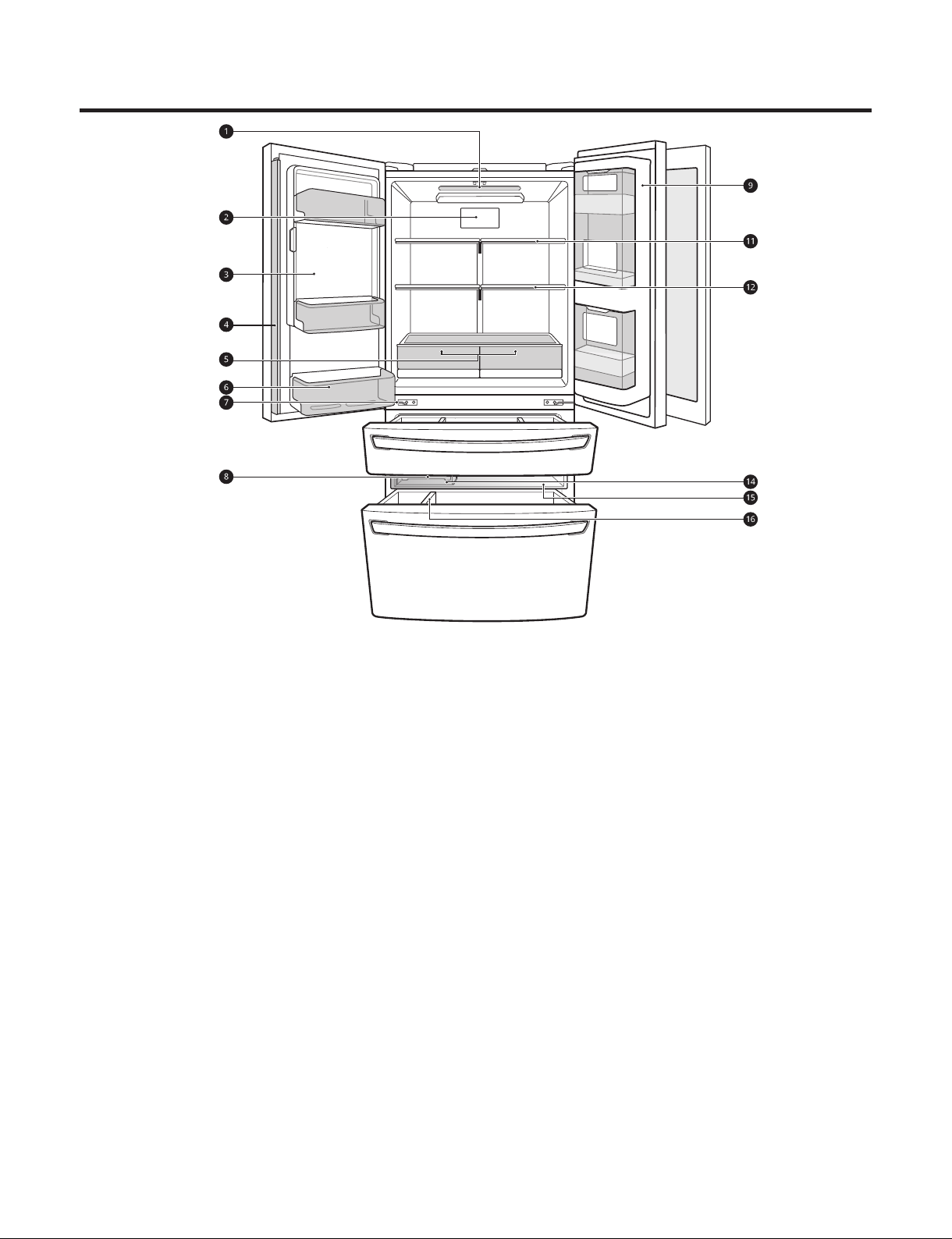
2. PARTS IDENTIFICATION ................................................................................................................................. 4
3. DISASSEMBLY ............................................................................................................................................ 5-24
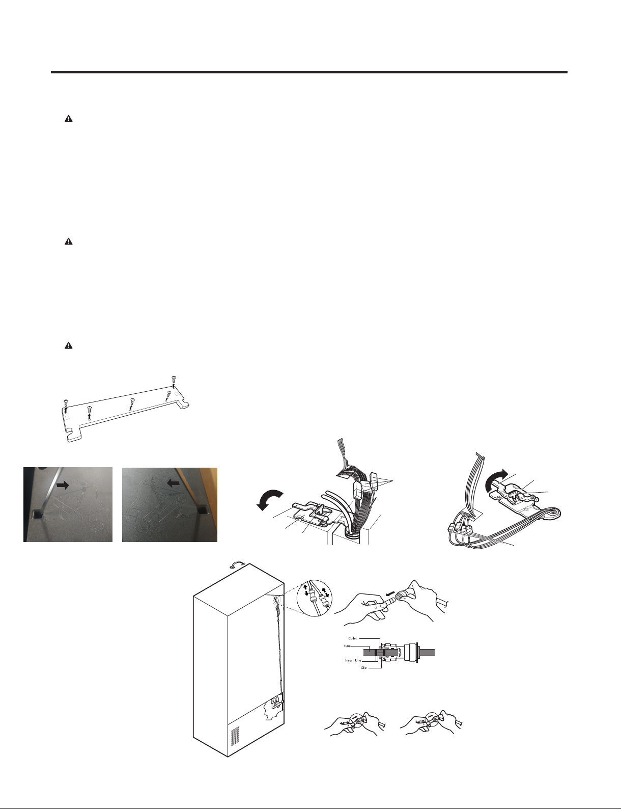
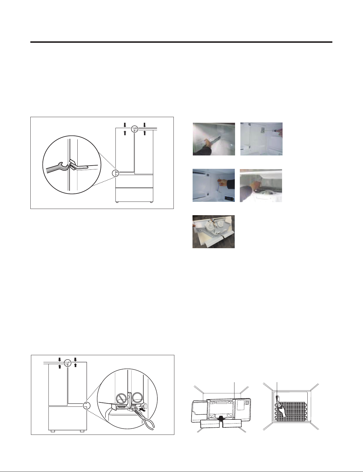
REMOVING AND REPLACING REFRIGERATOR DOORS ................................................................................................. 5
DOOR ..................................................................................................................................................................................... 6
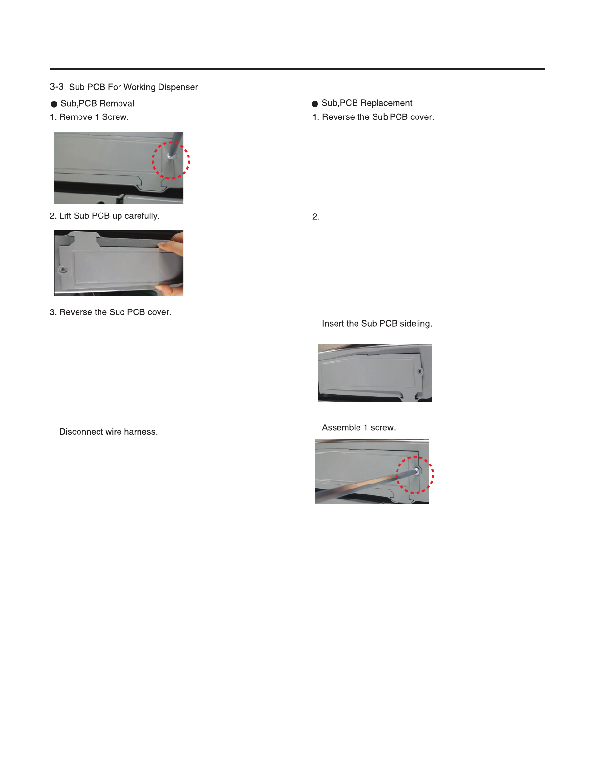
SUB,PCB ................................................................................................................................................................................. 7
DOOR ALIGNMENT .............................................................................................................................................................. 8
GRILLE FAN ASSEMBLY ...................................................................................................................................................... 8
DEFROST CONTROL ASSEMBLY ....................................................................................................................................... 8
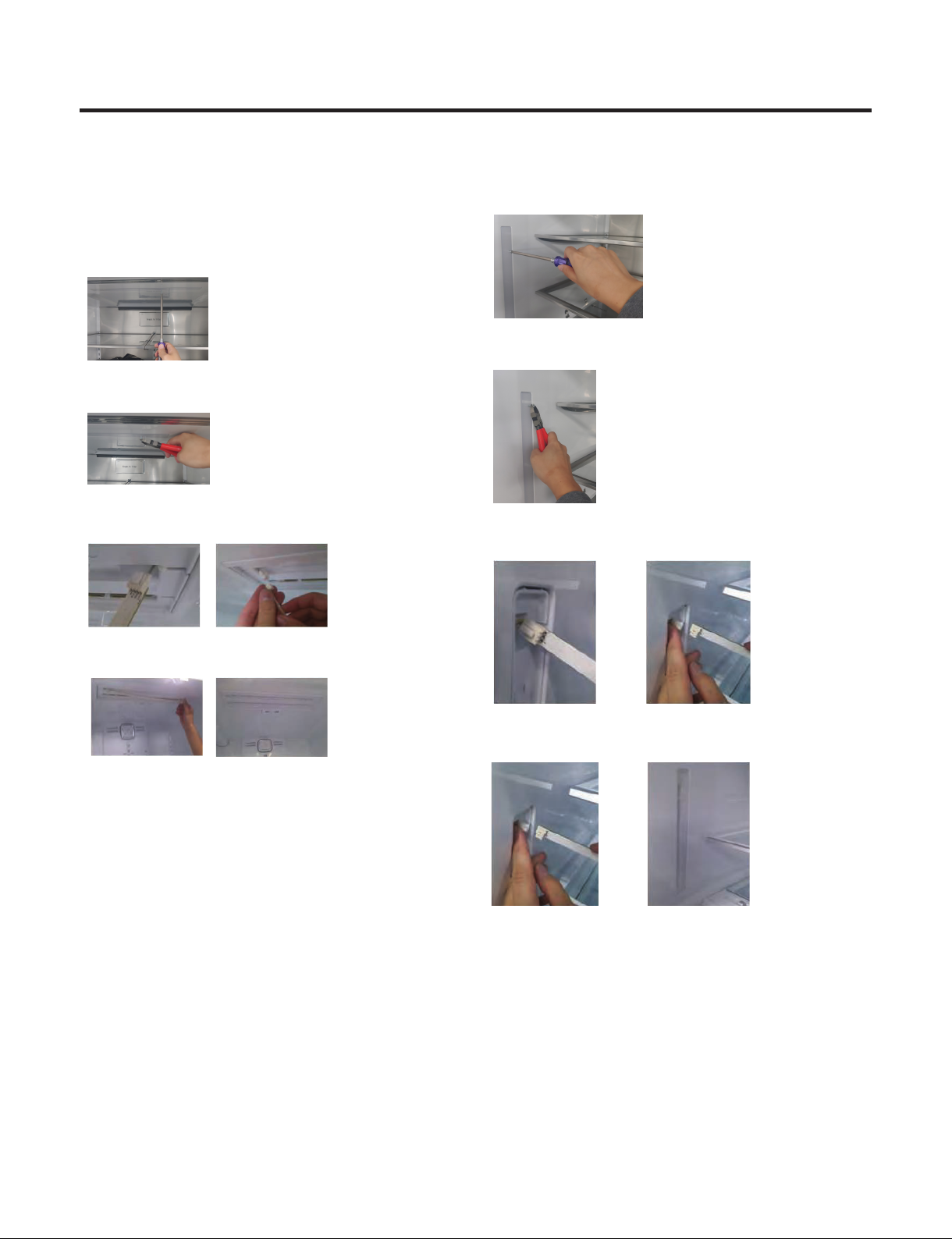
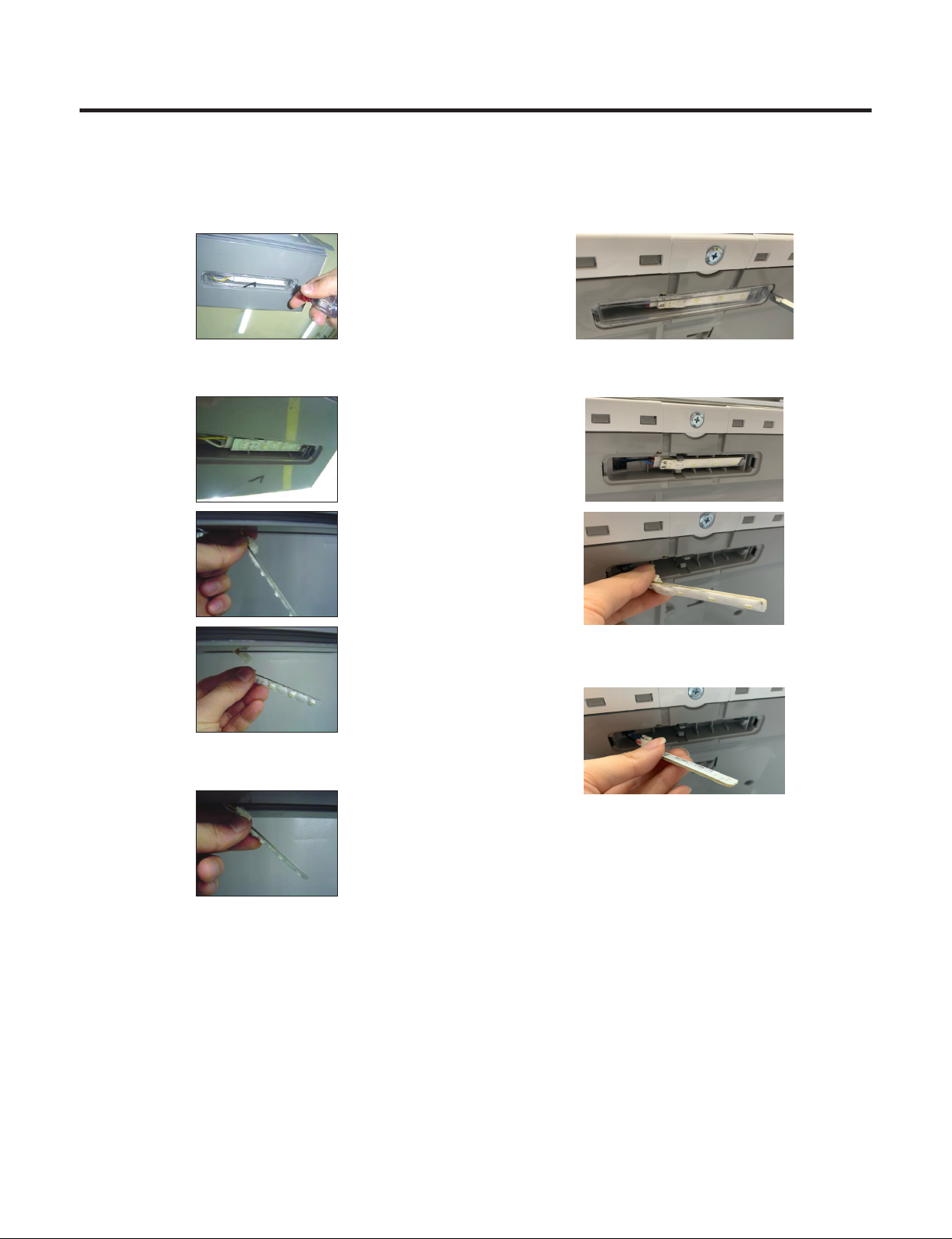
REFRIGERATOR LIGHT ....................................................................................................................................................... 9
MULTI DUCT ....................................................................................................................................................................... 11
FULL CONVERT DRAWER DISPLAY ................................................................................................................................ 11
ICE CORNER DOOR REPLACEMENT .............................................................................................................................. 12
ICEMAKER REPLACEMENT .............................................................................................................................................. 12
CAP DUCT MOTOR REPLACEMENT ................................................................................................................................ 13
HOW TO REMOVE A ICE BIN ............................................................................................................................................ 13
HOW TO REMOVE AND REINSTALL FILTER .................................................................................................................... 14
HOW TO REMOVE AND REINSTALL THE FREEZER DRAWER ................................................................................ 18-19
WATER VALVE DISASSEMBLY METHOD ........................................................................................................................ 20
FAN AND FAN MOTOR DISASSEMBLY METHOD ............................................................................................................ 20
PULL OUT DRAWER .......................................................................................................................................................... 17
CAUTION : SEALED SYSTEM REPAIR ............................................................................................................................. 21
WAY VALVE SERVICE ......................................................................................................................................................... 21
HOW TO REMOVE AND REINSTALL THE HOMEBAR....................................................................................................... 22
HOW TO REMOVE AND REINSTALL THE HOMEBAR DOOR ........................................................................................... 23
HOW TO REMOVE AND REINSTALL THE DOOR FOAM ASSEMBLY, REFRIGERATOR................................................ 24
HOW TO REMOVE THE CASE HOME BAR............................................................................................................................ 25
HOW TO REMOVE THE CASE ASSEMBLY LAMP .............................................................................................................. 26
4. ADJUSTMENT ................................................................................................................................................. 27
COMPRESSOR.......................................................................................................................................................................... 27
5. CIRCUIT DIAGRAM ......................................................................................................................................... 28
6. TROUBLESHOOTING ................................................................................................................................ 29-30
7. PCB PICTURE ............................................................................................................................................ 31-32
8. Troubleshooting With Error Display ........................................................................................................ 33-82
9. Reference .................................................................................................................................................... 83-85
10. COMPONENT TESTING INFORMATION ................................................................................................. 86-97
11. COMPRESSOR TROUBLESHOOTING ................................................................................................. 98-110
12. ICEMAKER OPEARTING AND TROUBLE SHOOTING ....................................................................... 111-114
13. ICE MAKER (Freezer Room) OPERATING METHOD AND TROUBLE............................................... 115-118
SAFETY PRECAUTIONS
Please read the following instructions before servicing your refrigerator.
1. Unplug the power before handling any elctrical componets.
2. Check the rated current, voltage, and capacity.
3. Take caution not to get water near any electrical components.
4. Use exact replacement parts.
5. Remove any objects from the top prior to tilting the product.
14. DESCRIPTION OF FUNCTION & CIRCUIT OF MICOM ....................................................................... 119-122
Copyright © 2019 LG Electronics Inc. All rights
reserved. Only training and service purposes.
FREEZER LIGHT ................................................................................................................................................................. 10
FULL CONVERT DRAWER ................................................................................................................................................. 15
HOW TO REPLACE THE SENSOR FROM FULL CONVERT DRAWER ............................................................................ 16

-3-
1. SPECIFICATIONS
1-1 LRMVS3006*
DOOR DESIGN
DIMENSIONS (inches)
NET WEIGHT (pounds)
COOLING SYSTEM
TEMPERATURE CONTROL
DEFROSTING SYSTEM
DOOR FINISH
HANDLE TYPE
INNER CASE
INSULATION
ITEMS
Side Rounded
35 3/4 X 38 1/8 X 70 1/4 (WXDXH) 29.5cu.ft.
368lb (167kg)
Indirect Cooling
Micom Control
Full Automatic
Heater Defrost
PCM, VCM, Stainless
Bar
ABS Resin
Polyurethane Foam
SPECIFICATIONS
●29.5 cu.ft.
VEGETABLE TRAY
COMPRESSOR
EVAPORATOR
CONDENSER
REFRIGERANT
LUBRICATING OIL
DEFROSTING DEVICE
ITEMS
Clear Drawer Type
Linear
Fin Tube Type
MC
R-600a (55 g)
ISO10 (280 ml)
SHEATH HEATER
LED Module
LED Module
SPECIFICATIONS
LAMP REFRIGERATOR
FREEZER
●DIMENSIONS
Copyright © 2019 LG Electronics Inc. All rights
reserved. Only training and service purposes.
B
A
CD
FI
H
E
G
-Dimension/Clearance LRMDS3006* LRMDC2306*
LRMVS3006* LRMVC2306*
A Depth without Handle 35 3/4" (908 mm) 28 7/8" (731 mm)
B Width 35 3/4" (908 mm) 35 3/4" (908 mm)
C Height to Top of Case 69 1/8" (1753 mm) 69 1/8" (1753 mm)
D Height to Top of Hinge 70 1/4" (1785 mm) 70 1/4" (1785 mm)
E Back Clearance 2" (50 mm) 2" (50 mm)
F Depth without Door 31" (785 mm) 24 1/8" (610 mm)
G Depth with Handle 38 1/8" (968 mm) 31 1/4" (793 mm)
H Depth (Total with Freezer Drawer
Open)
59 3/8" (1508 mm) 47 3/4" (1213 mm)
I Depth (Total with Door Open 90°) 50 1/8" (1272 mm) 43 1/4" (1097 mm)

-4-
2. PARTS IDENTIFICATION
Copyright © 2019 LG Electronics Inc. All rights
reserved. Only training and service purposes.
aLED Interior Lighting
Lights up the inside of the refrigerator.
bAir Filter
Reduces odors inside the refrigerator compartment.
cIn-Door Icemaker (Refrigerator)
This is where ice is automatically produced and stored.
dDoor Mullion
Prevents the cold air in the refrigerator from escaping
when the doors are closed.
eHumidity Controlled Crisper
Helps vegetables and fruit to stay crisp
and controls humidity.
fFixed Door Bin
Stores chilled food or drinks.
gAuto-Closing Hinge
The refrigerator doors and freezer drawers
close automatically when pushed slightly.
hAutomatic Icemaker (Freezer)
Dispenses ice automatically.
iDoor-in-Door Case
A convenient storage area for frequently-used items
that require easy access.
jCheese & Butter and Condiment Bins
Cheese & Butter and Condiment bins are specially designed
for these items, making spreading butter and slicing cheese easier.
kAdjustable Refrigerator Shelf
The refrigerator shelves are adjustable
to meet individual storage needs.
lFolding Shelf
Store taller items, such as gallon containers or bottles,
by pushing the front half of the shelf underneath
the back half of the shelf.
mModular Door Bin
Interchangeable bins can be arranged to suit storage needs.
nIce Bin
Stores ice from the freezer icemaker.
oPullout Drawer
Provides extra storage within the freezer compartment.
pDurabase and Durabase Divider
Provides storage for large frozen food items.

-5-
3. DISASSEMBLY
3-1 REMOVING AND REPLACING REFRIGERATOR DOORS
●
Removing Refrigerator Door
CAUTION: Before you begin, unplug the refrigerator. Remove food and bins from doors.
● Left Door -FIG. 2
1. Disconnect water supply tube by pushing back on the disconnect ring.-FIG. 1
2. Open door. Loosen top hinge cover screw (1).
4.Disconnect door switch wire harness and remove the cover.
5.Pull out the tube.
6.Disconnect all wiring harnesses (4). Remove the grounding screw (5).
7.Rotate hinge lever (6) counterclockwise. Lift top hinge (7) free of hinge lever latch (8).
8.Lift door from middle hinge pin and remove door.
9.Place the door with the insides facing up, on a not scratch surface.
CAUTION: When lifting hinge free from the latch, be careful that door does not fall forward.
● Right Door -FIG. 3
1. Open the door, Loosen top hinge cover screw (1). Lift up cover (2).
2. Disconnect all wiring wire harnesses (3)
3. Rotate hinge lever (4) clockwise. Lift top hinge (5) free of hinge lever latch (6).
4.Lift door from middle hinge pin and remove door.
5. Place the door with the insides facing up, on a not scratch surface.
CAUTION: When lifting hinge free from the latch, be careful that the door does not fall forward.
Correct Incorrect
(6)
(7) (8)
(4)
(5)
Figure 2
Figure 1
1) Insert the tube until you can see only one of
the lines printed on the tube.
2) After inserting, pull the tube to ascertain that
it is secure.
3) Assemble clip.
(1)
(2)
Copyright © 2019 LG Electronics Inc. All rights
reserved. Only training and service purposes.
(2)
Figure 4 (Left) Figure 4 (Right)
(If FIG.4 is engraved) Using a flat tip screwdriver, remove the left and right hooks as shown in the engraving.
Use flat tip screwdriver to pry back hooks on front underside of cover (2). Lift up cover.
3.
(4)(5)(6)
(3)
Figure 3

-6-
1. Remove gasket
Remove the gasket from gasket channel at doorliner as
shown in the illustration below.
3-2 DOOR
Mullion Removal
1. Remove 2 screws.
Door Gasket Removal
2. Lift mullion up carefully.
3. Disconnect wire harness.
Door Gasket Replacement
1. Insert gasket into channel
Insert and press gasket into channels at doorliner.
2. Insert mullion into channel.
Insert the mullion into channel at door as shown below.
Mullion Replacement
1. Connect wire harness.
3. Assemble 2 screws.
Gasket
Gasket
Channel
Copyright © 2019 LG Electronics Inc. All rights
reserved. Only training and service purposes.

-7-
3.
Connect wire harness.
4.
4.
Copyright © 2019 LG Electronics Inc. All rights
reserved. Only training and service purposes.

-8-
1) Remove the plastic guide for slides on left side by
unscrewing phillips head screws.
2)
3)
Pull out the cover grille to disassemble by using tools
shown in the figure.
4)
Put your hand into the inside of grille to disassemble
shown in the figure.
5)
Disconnect wire harness of the grille assembly.
Replace the grille fan assembly.
(1) (2)
(3) (4)
(5)
3-7 DEFROST CONTROL ASSEMBLY
Defrost Control assembly consists of Defrost Sensor and
FUSE-M.
The Defrost Sensor works to defrost automatically. It is
attached to the metal side of the Evaporator and senses its
temperature. At 46F(8°C), it turns the Defrost Heater off.
Fuse-M is a safety device for preventing over-heating of
the Heater when defrosting.
1. Pull out the grille assembly. (Figure 1)
2. Separate the connector with the Defrost Control
assembly and replace the Defrost Control assembly after
cutting the Tie Wrap. (Figure 2)
3-4 Left Door Alignment
If the level of refrigerator doors is uneven, follow the
instructions below to align the doors:
Turn the leveling legs (CW) to raise or (CCW) to lower the
height of the front of the refrigerator by using flat blade
screw driver or 11/32" wrench. Use the wrench (Included
with the Owners Manual) to adjust the bolt in the door hinge
to adjust the height. (CW to raise or CCW to lower the
height.)
3-5 Right Door Alignment
GRILLE ASSEMBLY DEFROST-CONTROL
ASSEMBLY
The right refrigerator door does not have an adjustable nut.
If the space between the doors is uneven, follow
the instructions below to align the right door:
1 With one hand, lift up both the inner and outer door
sections of the right door to raise them at the middle hinge.
(It may be easier to lift it with the doors open.)
2 With the other hand, use pliers to insert the
snap ring on the middle hinge of the inner
door section as shown. Do not insert the ring
on the hinge of the outer door section.
3 Insert additional snap rings until the right
door is aligned. (Two snap rings are provided
with the unit.)
Copyright © 2019 LG Electronics Inc. All rights
reserved. Only training and service purposes.
3-6 Grille Fan Assembly Replacement

-9-
3-8 Refrigerator Light (Top) 3-8-2 Refrigerator Light (Side)
Unplug Refrigerator, or disconnect power at the circuit
breaker.
If necessary, remove top shelf or shelves.
1. Unplug refrigerator power cord from electric outlet.
2. Tighten a screw to the cover.
4.Remove the LED assembly from connector.
5.Replace LED assembly.
6. Assemble the cover.
1. Unplug refrigerator power cord from electric outlet.
2. Tighten a screw to the cover.
3.Pull a screw using a Plier and disassemble the cover.
4.Remove the LED assembly from connector.
5. Replace LED assembly.
6. Assemble the cover.
Copyright © 2019 LG Electronics Inc. All rights
reserved. Only training and service purposes.

-10-
3-8-3 Cap Decor LED LAMP(Freezer Upper)
1. Unplug refrigerator power cord from electric outlet.
2. Open the refrigerator door to need diassembly.
3. Put flat screwdriver into service hole, remove the cover
of cap decor LED LAMP.
5. Replace LED assembly.
6. Assembly the cover in reverse order.
4. Remove the LED assembly from connector.
Copyright © 2019 LG Electronics Inc. All rights
reserved. Only training and service purposes.
3-8-4 Barrier LED LAMP(Freezer Lower)
1. Unplug refrigerator power cord from electric outlet.
2. Open the freezer door to need diassembly.
3. Put flat screwdriver into service hole, remove the cover
of barrier LED LAMP.
5. Replace LED assembly.
6. Assembly the cover in reverse order.
4. Remove the LED assembly from connector.

3-9 MULTI DUCT
2. Remove 1screws and disassemble Duct Assembly,Connector .
4.
5.
Disconnect the lead wire on the bottom position
Grip both side of multi duct, pull it out.
1. Remove 2screws and Guide Rail .
3. Disconnect connector.
3-10 Full Convert Drawer Display
2.Put a flat screwdriver and a steel ruler into the corner
of full convert display.
1. Unplug refrigerator power cord from electric outlet.
3.Pull the display using a flat screwdriver.
4.Replace the display.
-11-Copyright © 2019 LG Electronics Inc. All rights
reserved. Only training and service purposes.

-12-
3-12 Ice corner door replacement
1) Loosen the front screw as shown in the picture.
2) Remove the Cover Home Bar as shown in the picture.
hinge
3-11 Dispenser
3) Lift up the hinge with one hand.
4) Pull out the Ice Corner Door with the other hand.
Cover Home
Bar
XUGoGGGGGGkG
GGG GGG
GGU
mGovvr
* If there is a problem with the WiFi module, please
change the whole display.
YUGhGGGGkGGG
SG G GZGGG~GoU
ZUGhGGGGGGGSGG
GGG G¡GGGk
UGGhGGSGGGZGoGGGGG
GkSGGGˈTTˉGGU
Gjh|{pvu
GkGGGGGGGGG
GG~GoGGGGGGGkGGG
GGGGGG~GU
3-11 Icemaker replacement
1) Remove 3 screws marked in the picture below.
2) Grasp the bottom of motor cover assembly and pull it out
slowly to remove.
3) Disconnect wire harness from wall of compartment.
Copyright © 2019 LG Electronics Inc. All rights
reserved. Only training and service purposes.

-13-
3-12 CAP DUCT MOTOR REPLACEMENT
1)
Separate the Housing of the Cap Duct Motor.
3) Replace the motor and push housing aside.
Duct Door
Cap Duct
Motor
2)
Unscrew 3 screws to disassemble the motor.
5) Insert 3 screws.
BINICE
3-13 HOW TO REMOVE
1) Grip the handles, as shown in the picture.
2) Lift the lower part slightly.
3) Take the Ice Bin out slowly.
Copyright © 2019 LG Electronics Inc. All rights
reserved. Only training and service purposes.
Replace the motor and check the position of the door
duct and the link for proper fit.
4)

-14-
→ →
3-14 Module filter Replacemen
1) Loosen the 3 screw
3-15 Module filter part Replacement
2) Hold the connector and then Turn 90 to disconnect
from Filter head Turn 90 the water tank to disconnect
from Filter Head
3) Rotate the connector and pull out
Copyright © 2019 LG Electronics Inc. All rights
reserved. Only training and service purposes.
1)

3-16 FULL CONVERT DRAWER
3-16-1 Follow Steps to Remove
1 Pull the drawer open to full extension.
Remove the basket by lifting the basket from
the rail system.
2 Hold both sides of the door and lift it to
remove it from the rail system.
3-16-2 Follow Steps to Reinstall
1 Grasp the door on each side and lower it into
place on the rail system.
2 Pull the drawer open to full extension. Lower
the basket onto the rail system.
-15-Copyright © 2019 LG Electronics Inc. All rights
reserved. Only training and service purposes.

3-17 HOW TO REPLACE THE SENSOR FROM FULL CONVERT DRAWER
1) Pull the drawer open to full extension
2)Pull out door.
3)Loosen a screw.
4)Disassembly Sensor from connector rail.
-16-Copyright © 2019 LG Electronics Inc. All rights
reserved. Only training and service purposes.

3-18 PULL OUT DRAWER
1 Pull the drawer open to full extension.
2 Gently lift and pull out the ice bin.
3 Lift the front of the drawer up, then pull it
straight out.
-17-Copyright © 2019 LG Electronics Inc. All rights
reserved. Only training and service purposes.

-18-
3-19 HOW TO REMOVE AND REINSTALL THE FREEZER DRAWER
3-19-1 Follow Steps to Remove
Copyright © 2019 LG Electronics Inc. All rights
reserved. Only training and service purposes.

-19-
3-19-2 Follow Steps to Reinstall
Copyright © 2019 LG Electronics Inc. All rights
reserved. Only training and service purposes.

-20-
3-20 WATER VALVE DISASSEMBLY METHOD 3-21 FAN MOTOR ASSEMBLY AND
1) Turn off the water to unit. Remove the waterline from the
valve.
DISASSMEMBLY METHOD
1) Remove screws for the Drain Pipe Assembly and the 1
connected to the Motor Cover.
2) Remove cover and 1 screw from the valve.
3) Separate the housing and remove the valve.
4) Remove the clip, and press the collet to separate the
tube from the connector. Note: there maybe some water
in the line.
Mechanical Cover
Housing
2) Remove the screw from shroud and Separate the Fan
motor assembly and Shroud.
Assemble in reverse order. Taking care to avoid.
1. Do not to bend the tube during assembly.
2. Press the Water Dispenser button letting water pour out,
this checks for any leaks in the tube connection, this may
vary depending on the water pressure
( about 2 minutes.).
Copyright © 2019 LG Electronics Inc. All rights
reserved. Only training and service purposes.
This manual suits for next models
4
Table of contents
Other LG Refrigerator manuals

LG
LG GR-M752GSH User manual

LG
LG GB3133PVGW User manual

LG
LG LBNC15251 Series User manual

LG
LG GB33 Series User manual

LG
LG GR-N266LLR User manual

LG
LG GR-B652JLP User manual

LG
LG BOTTOM FREEZER REFRIGERATOR User manual

LG
LG GL-B201APZZ User manual

LG
LG LFXC24726 Series User manual

LG
LG LTC24380 Series User manual