LG LSXS26336V User manual

MODELS:
CAUTION
PLEASE READ CAREFULLY THE SAFETY PRECAUTIONS OF THIS MANUAL
BEFORE CHECKING OR OPERATING THE REFRIGERATOR.
REFRIGERATOR
SERVICE MANUAL
LSXS26336V
LSXS26336D

CONTENTSCONTENTS
SAFETY PRECAUTIONS ................................................................................................ ............................ 3
1. SPECIFICATIONS .......................................................................................... .......................................... 4
2. PARTS IDENTIFICATION ......................................................................... ............................................... 5
3. DISASSEMBLY ................................................................................................. ....................................... 6
1. Door Alignment.......................................................................................................................................... 6
2. Install Water Filter...................................................................................................................................... 7
3. Refrigerator Shelves.................................................................................................................................. 7
4. Icemaker.................................................................................................................................................... 8
4. HOW TO DISASSEMBLY AND ASSEMBLY................................................ ............................................ 9
1. Removing and Replacing Refrigerator door.............................................................................................. 9
2. Handle Removal........................................................................................................................................ 10
3. Redd S/W.................................................................................................................................................. 11
4. Removing and Replacing Refrigerator and Freezer Led’s........................................................................ 11
5. Fan Shroud Grille....................................................................................................................................... 12
6. Water Valve Tubes Assembly Method....................................................................................................... 13
7. Way Valve Service..................................................................................................................................... 14
8. Dispenser .................................................................................................................................................. 15
9. Disassembly of Fan Motor ………………………………………………………………………………………. 17
5. MICOM FUNCTION ................................................................................................ ................................. 18
6. ICEMAKER AND DISPENSER WORKING PRINCIPLES AND REPAIR................................................ 26
1. Working Principles..................................................................................................................................... 26
2. Function on Icemaker................................................................................................................................ 27
3. Ice maker Troubleshooting........................................................................................................................ 30
4. Icemaker Circuit........................................................................................................................................ 31
7. CIRCUIT DIAGRAM................................................................................... ............................................... 32
8. TROUBLE DIAGNOSIS.......................................................... .................................................................. 33
9. PCB ………………………………………………………………………………………………………….......... 55
10. TROUBLESHOOTING WITH ERROR DISPLAY ……………………………………………………....…… 56
11. TROUBLESHOOTING WITHOUT ERROR DISPLAY ……………………………………………………… 74
12. EXPLODED VIEW .................................................................................................................................106

Safety Warning and Cautions
Chapter 1 Safety Warning and Cautions
► Observing cautions for safety can prevent accidents and dangers.
► Cautions are classified into Warning and Caution and the meanings are as follows
WARNING indicates the possibility of serious injury or death if the
instructions are not followed.
Caution indicates a hazardous situation with the possibility of product
damage or personal injury if the instructions are not followed
WARNING
CAUTION
WARNING
Be cautious of electric shock.
Control board (PWB Main and Sub)
uses power supply of about 120 VAC.
Do not allow consumers to directly
repair, disassemble, or modify the
refrigerator.
Harm, electric shock,
or fire could occur.
Be sure the plug and cord are not
pressed by the rear side of the
refrigerator.
Damage to power plugs
could result in fire or
electric shock.
Plug the refrigerator into a
dedicated circuit.
Plugging in too many appliances
can result in fire or problems with
the operation of your refrigerator.

If grounding is required, be sure to
consult an electrician.
The refrigerator
must be plugged in
to a properly rated
and grounded
outlet. If you are
not sure of your
voltage or ground,
consult a qualified
and licensed
electrician.
Do not store poisonous,
flammable, or explosive chemicals
in the refrigerator.
There is danger of
explosion and fire.
Do not store medications or
biohazardous products requiring
precise temperature control.
Do not use the refrigerator to store
papers, electronic storage media,
or similar items.
The refrigerator is
for storing food.
This is a consumer
household
appliance and not a
precision device.
If storing or disposing of the
refrigerator, remove the doors
to eliminate the possibility of
children playing in it.
Children may
become entrapped in
the refrigerator.
Unplug the refrigerator for
cleaning or repair. Be sure your
hands are dry when handling the
power cord or plug.
Electric shock or
harm may occur.
Be sure the plug and socket are
clean and the connection is tight.
Dust or incomplete
connection may
result in fire.
Grounding nut
Grounding wire
More than
75cm
Copper
plate
Firstly take power socket out for
Electric shock may occur.
When dusts etc are stained to the
pin part of the power socket,
cleanly wipe out them.
Fire may occur.
Safety Warning and Cautions
WARNING

Do not alter the power cord.
Replace it only with an exact factory
replacement part.
Electric shock or
fire may occur
due to electrical
damage of power
cables.
Do not place heavy objects on the
refrigerator.
Falling objects when
opening or closing doors
may cause injury.
Do not hang or swing from the
refrigerator doors.
Do not allow children to
play with the refrigerator.
The refrigerator may turn
over. Hands and fingers
may be pinched.
Do not use flammables near a
refrigerator.
There is danger of fire.
Do not install the refrigerator next
to a stove or other sources of heat.
There is danger of fire.
When a gas leak occurs, do not
unplug the refrigerator. Open the
doors for ventilation.
There is danger of
burning due to
explosion and
sparking.
Do not clean the refrigerator by
spraying water inside or outside.
It may result in
product damage,
fire, or electric
shock.
This refrigerator is designed for
use as a consumer home
appliance only.
It is not a precision
device for storing
medication or valuables.
Do not install the
refrigerator in a vehicle,
aircraft, maritime vessel,
or other than in a home
environment.
If the refrigerator is submerged or otherwise inundated
with water, have it checked by an authorized servicer.
Electric shock or fire may occur.
Safety Warning and Cautions
WARNING

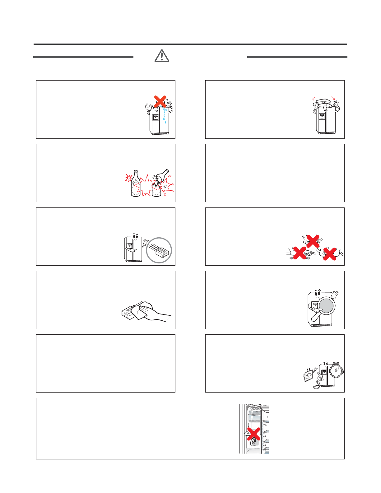
Do not put glass bottles or other
sealed containers in the freezer.
They may burst, leaving
glass fragments in the food
and possibly causing injury.
Be sure to use rated parts for
replacement of electric parts.
Use factory replacement parts.
Secure the cord behind the
refrigerator.
Do not allow the cord to
hang where it can be
pinched, damaged, or rolled
over by the refrigerator.
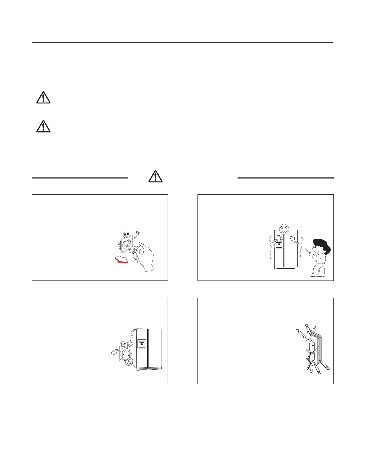
Pull the plug out by the plug body;
do not pull the wire to disconnect
the cord.
Damage to power cords
may cause fire or electric
shock.
Keep electrical parts and
connections free from dust and
contamination.
There is danger of fire
from shorting or arcing.
Be sure replacement parts are an
exact fit.
Replacement parts should look
and fit exactly like the original
parts and have the same electric
rating.
Do not let moisture drop onto
electrical parts.
If there is a problem in this area, replace the
parts or tape the wires to prevent
contamination and degradation.
If you unplug the refrigerator or
turn off the power, wait 5 minutes
before plugging it back in
or turning the power on.
Rapid cycling of the compressor
could cause failure.
Do not put your hands, fingers, tools, or other
objects into the icemaker, crusher, or discharge
outlet. Do not check the operation of the ice
dispenser or crusher in this manner.
You may damage your product, fingers, or tools.
Do put the vessel that flower base,
cup, cosmetics or drugs, etc
are contained on the
refrigerator.
Fire or electric shock may occur, or
injury due to dropping may occur.
Do not accumulate objects on a
refrigerator or do not keep
foods in random method.
Dropping of objects when opening
or closing the door may cause
physical injury.
Safety Warning and Cautions
WARNING

Unplug the refrigerator if it is
going to be unused for an
extended period.
Remove all food items,
wipe down the inside of
the refrigerator, dry it
thoroughly, and prop the
doors open to allow air
circulation.
Be sure the floor will support the
weight of the refrigerator.
If the refrigerator is not installed
at a firm, level location, the
doors and icemaker may not
operate properly.
Do not install the refrigerator in a
place where it is subject to
splashing and excess moisture.
Deterioration of insulation
may cause electrical
leakage.
To carry the refrigerator, use the
handles at the top of the back, and
beneath the edge of the front.
Using these handles will
ensure safety and reduce
the possibility of injury.
Do not touch foods, containers, or
the inside of the freezer
compartment with wet hands.
Your hands may stick
to the cold items. It
could cause frost bite.
Be careful to avoid pinching hands
or feet when opening the doors.
Do not stick your hands or fingers
under the bottom of the
refrigerator.
Watch out for sharp
edges.
Do not put live animals in the
refrigerator.
power plugs catching with the end
of plugs without catching cords.
Fire may occur due to electric
shock or short-circuit.
Do not use power cords or power
plugs when they are damaged or
holes of power plugs are loose.
Fire may occur due to
electric shock or
short-circuit.
Safety Warning and Cautions
WARNING

Product Standards
LSXS26336V / LSXS26336D
742.49L (26.22 Cu.)
260.59L (9.20 Cu.)
481.90L (17.02 Cu.)
35 7/8" x 35 7/8" x 70 3/8"
298
105 ± 15%(W)
Heater 260 ± 10%(W)
Indirect cooling(F-Control)
Temperature
control MICOM(Outside)
Forced method
Auto
Auto
Forced method
Cyclo-Pentane
3
1
3
-
-
2
A Logic Inverter operaon
Pin tube type
Forced convecon method
Freol Alpha5 oil(175cc)
R134a(175g)
Φ0.75
MOLECULAR SIEVE XH-9
Inial defrost 4~5 hours (vary depending on condion)
Defrost cycle 9~11 hours (vary depending on condion)
niM3emittseR
Defrost sensor Returend to defrost funcon when reaching to 5
Temp.fuse (rated/
C°27/V052)erutarepmetnoitarepo
W062/V511CAhtaehSretaeH
-retaehroodtcudresnepsiD
-retaehrabemohmooR-R
-retaehrabemohmooR-F
W5.2/V21CDretaehresnepsiD
Fµ02/V054CAgninnuR’pmoC
I/maker geared motor
Fµ41/V054CAg
ninnuR
Magic room Damper Heater -
R-Room Damper Heater DC 12V / 1W
-retaeHknaTretaW
W8.0/V21CDretaeHylppusretaW
MRA12325
DC 13V
DC 13V
DC 12V / 5W (1EA)
DC 12V / 5W (1EA)
250 V / 0.5 A
250 V / 0.5 A
250 V / 10 A
AC 125 V / 10 A
Main Fuse
Power cord
Inside lamp at R-Room
Door switch (F-Room/R-Room)
Home bar door switch
F-Room fan motor
Fan motor for cooling condenser
Inside lamp at F-Room
For prevenng ice
making
Overload protecve device
Capacitor
Electrical Standard
parts
Parts related with
dewing prevenon
Capillary tube
Dryer (drying tube)
Freezing cycle
Compressor driving method
Evaporaon
Condenser
F-Room oil
Type of refrigerant
R-Room
Fixed Shelf
Shelf(Movable, Folding)
Egg container
Vegetable room
F-Room Fixed Shelf
Drawer
Defrost
Method
Start
End
Evaporaon
Type of heat shield
F-Room
Cooling method
F-Room
Outer dimension ( W X D X H )
Product weight (lb)
Rated consumpon power of motor
Model
Effecve inner
capacity
Total inner capacity(L)
F-Room
R-Room

Circuit Diagram

Specications
1. Specications
ltem
Width
Depth
Height
Minimum air
circulation
space
Model
Width (A)
When opening door by 90° (including handle) (B)
Case (including back handle) (C)
After disassembling door (including hinge, L) (D)
Including door (not including handle) (E)
Including handle (F)
When opening door by 90° (G)
Cabinet (H)
Including cover PWB (J)
Including door (K)
Top part
Side
Rear part
35.9 (912)
39.6 (1005)
28 7 730. ( )
31 5 800. ( )
33 4 848. ( )
35 9 912. ( )
50 6 1285. ( )
68 9 1750. ( )
69 3 1760. ( )
70.3 (1785)
11.8 (300)
0.8 (20)
2.0 (50)
Unit : inch (mm)
Front View
Top View
LSXS26336V / LSXS26336D

2. Main Name
MODEL : LSXS26336*
Appearance Size of Refrigerator and Name of Every Part
Freezer
Compartment
Refrigerator
Compartment
Automatic
Icemaker
Shelf
LED Lamp
Freezing Zone
Door Bin
Shelf
LED Lamp
Filter
Dairy Corner
Door Bin
Door Bin
Door Bin
Fresh zone

Micom Function
1. Operating Panel
c) MODEL : LSXS26336*
Ice Plus
Ice Plus
Button(1sec)
Ice On/Off
Ice Making
On/Off
Button(3sec)
Freezer
Temperature
adjustment
button for
freezer
compartment
Dispenser
Dispenser
Selection
Button(1sec)
Water Filter
Water Filter
Reset
Button(3sec)
ARefrigerator
Temperature
adjustment button
for refrigerator
compartment
Door Alarm
Door Alarm
Button(1sec)
Lock
Display
Lock/Unlock
Button(3sec)
E

Micom Function
Models: LSXS26336*
1-1. Display Function
When the Appliance is plugged in, it is set to step 4 for refrigerator and freezer. You can adjust the Refrigerator and the
Freezer control temperature by pressing the Freezer and Refrigerator Button.
When the power initially applied or restored after a power failure, it is set to the previously controlled temperature.
1-2. Demonstration Mode (OFF Mode)
1-3
1-4. Filter cartridge status reset button
1 Any Door must be opened to enter in this mode
2 To activate this mode press and hold ULTRA ICE and REFRIGERATOR TEMP button over 5 seconds
3 The display will show the word OFF”.
4 In this mode all loads are turned off Compressor Heater Fans etc
5 Lamps and Dispenser Functions works normally even in demonstration mode the refrigerator Lamp automatic off function
works normally
6 To exit Demonstration mode open any Door then press and hold and REFRIGERATOR TEMP button over 5
seconds Display return to normal mode
1) When the refrigerator is first turned on, the buttons are not locked. The display panel shows the padlock unlocked icon.
2) To lock the display, the dispenser, and the control panel, press, and hold the ALARM/LOCK button for 3 seconds. The
locked pad lock icon is displayed.
3) The ALARM/LOCK button is the only control feature that remains active in the locked state. The buzzer sound, other
control buttons, and the dispenser are deactivated.
4) To release from the locked state, press and hold the ALARM/LOCK button again for 3 seconds.
1) There is a replacement indicator for filter cartridge on the dispenser.
2) Water filter needs replacement once six months.
3) Initial filter icon condition is OFF.
4) After six months of use, change filter icon LED will be turned ON.
5) Once filter cartridge has been replaced, press and hold button for more than 3 seconds.
6) Icon LED will be turned OFF by a 6 months period.
.)
) .
“)
() , , , )
()
)
)
)( .
Ice Plus
Ice Plus
Water Filter
Key Lock Button (dispenser and display lock)
Ex) “LOCK”
Function OFF
Ex) “LOCK”
Function ON
In initial Power On /
Filter Reset
Replace indicator
light on

Micom Function
1-5. ICE PLUS selection
1-6. Ice Maker On/Off Button
1-7. Door Alarm Button
Please select this function for quick freezing.
1) Function is repeat icon whenever pressing button.
2) function automatically turns off after a fixed time passes.
1) When the Refrigerator is first turned on, the Ice Maker also turned On. And Ice Maker LED turned On.
2) If Ice On/Off Button is pressed and held for 3 seconds, Ice Maker OFF LED turned On.
3) To set Ice Maker On, press and hold the Ice On/Off button again for 3seconds.
1) When the Refrigerator is first turned on, the Door Alarm LED is turned on.
2) If Freezer or Refrigerator Door is opened and time has passed 60 seconds, Door Open Alert Sound is activated.
3) If time has passed 30 seconds after first Door Open Alert Sound is activated, Door Open Alert Sound is activated again.
4) Door Alarm Button is pressed, Door Alarm LED is turned Off and door open alert sound is deactivated.
Ice Plus Ice Plus
Ice Plus
ON OFF
ON OFF

2. Function description
2-1. Funnction of Temperature Selection
1. The actual inner temperature varies depending on the food status, as the indicated setting temperature is a target
temperature, not actual temperature within refrigerator.
2. Refrigeration function is weak in the initial time. Please adjust temperature as above after using refrigerator for minimum
2~3 days.
Notch
1st press
Power
Initiallly On
Freezer
Refrigeration
Micom Function
The automatic icemaker can automatically makes 120~ 220 cubes per day. This quantity may vary by usage condition, including
ambient temperature, door opening, freezer load, and etc.
Icemaker stops making ice when the ice storage bin is full.
If you don’t want to have the automatic icemaker make ices, press and hold ICE ON/OFF button until the indicator lights on. If you
want to have icemaker makes ices again, press and hold ICE ON/OFF button until the indicator lights off.
•When ice is lumped together, take the ice lumps out of the ice storage bin, break them into small pieces, and then place them into
the ice storage bin again.
When the ice dispenser produces too small or lumped together ice, the amount of water supplied to the ice dispenser need to be
adjusted. Contact the service center.
•If ice is not used frequently, it may lump together.
Ice may drop into the freezer compartment. Take the ice storage bin out and discard all the ice then dry it and place it back. After the
machine is powered again, the previous selection mode remains.
It takes about 12 hours for a newly installed refrigerator to make ice in the freezer compartment.
1. Ice Plus is function to improve cooling speed of the freezing room by consecutively operating compressors and freezing room
fan.
2. Ice Plus is released if power failure occurs and then returns to the original status.
3. Temperature setting is not changed even if selecting the Ice Plus.
4. The change of temperature setting at the freezing room or the cold storage room is allowed with Ice Plus selected and processed.
5. The cold storage room operates the status currently set with Ice Plus selected and processed.
6. If selecting the Ice Plus, the Ice Plus function is released after continuously operating compressor and freezing room fan.
7. If frost removal starting time is arrived during Ice Plus, Ice Plus operation is done only for the remaining time after completion of
frost removal when the Ice Plus operation time passes 90 minutes. If passing 90 minutes, Ice Plus operation is done only for 2 hours
after completion of frost removal.
8. If pressing Ice Plus button during frost removal, the Ice Plus LED is turned on but if pressing the Ice Plus, compressor operates
after the remaining time has passed.
9. If selection Ice Plus within 7 minutes (delay for 7 minutes of compressor) after the compressor stops, compressor operates after
the remaining time has passed.
2-3. When ice is not dispensed smoothly
2-4. Ice Plus
Ice is lumped together
Power failure
The unit is newly installed
•
2-2. Automatic ice maker
While ICE OFF indicator is on, Icemaker stops making ice. But you can dispense the ices until the ices run out from the ice
storage.Micom Function
Models: LSXS26336*
2nd press 3rd press 4th press 5th press 6th press 7th press

Doors of freezing /
cold storage room
or home bar
BUZZER
Micom Function
10. The freezing room fan motor operates at the high speed of RPM during operation of Ice Plus.
11. During 21 hours after Pill Down Operation, F-Room is controlled at Maximum F-Notch normally and F-Fan operates normal
RPM.
12. The light of Ice Plus would be turned off after Ice Plus.
13. Execute defrost immediately in case of defrost signal occurs in Ice Plus and defrosting time is included at execution time 21
hours.
14. If Ice Plus is started during 2nd Load response operation, 2nd Load response operation will be canceled.
15. If the button of Ice Plus in display is turned off, Ice Plus operation will be canceled. The compulsory operation of F notch in the
water tank’s preventing frost is prior to the one of Ice Plus.
2-5. Control of variable type of freezing room fan
2-6. Control of M/C room fan motor
2-7. Door opening alarm
2-8 Ringing of button selection buzzer
2-9. Ringing of compulsory operation, compulsory frost removal buzzer
1. To increase cooling speed and load response speed, MICOM variably controls freezing room fan motor at the high speed of
RPM and standard RPM.
2. MICOM only operates in the input of initial power or special freezing operation or load response operation for the high
speed of RPM and operates in the standard RPM in other general operation.
3. If opening doors of freezing / cold storage room or home bar while fan motor in the freezing room operates, the freezing
room fan motor normally operates (If being operated in the high speed of RPM, it converts operation to the standard RPM).
However, if opening doors of freezing room, the freezing room fan motor stops.
4. As for monitoring of BLDC fan motor error in the freezing room, MICOM immediately stops the fan motor by determining that
the BLDC fan motor is locked or poor if there would be position signal for more than 65 seconds at the BLDC motor.
Then it displays failure (refer to failure diagnosis function table) at the display part of refrigerator, performs re-operation in the
cycle of 30 minutes. If normal operation is performed, poor status is released and refrigerator returns to the initial status
(reset).
1. The M/C room fan motor performs On/Off control by linking with the Compressor.
2. If ambient temperature is under 34.5 , humidity condition is over 80%, there is not sensor error and the refrigerator do not
operate Ice Plus, first cycle after defrost, first cycle after power on, M/C room fan motor performs ON for 3minitus and OFF for
12minites repeatedly.
3. It controls at various RPM with ambient temperature and humidity condition.
4. Failure sensing method is same with freezing fan motor.(refer to failure diagnosis function table for failure display)
1. Buzzer generates alarm sound if doors are not closed even when more than a minute consecutively has passed with doors
of freezing / cold storage room or home bar opened.
2. Buzzer rings three times in the interval of 0.5 second after the first one-minute has passed after doors are opened and then
repeats three times of On/Off alarm in the cycle of every 30 seconds.
3. If all the doors of freezing / cold storage room or home bar are closed during door open alarm, alarm is immediately
released.
1. If pressing the front display button, “Ding ~ “ sound rings.
1. If pressing the test button in the main PCB, “Phi ~ “ sound rings.
2. In selecting compulsory operation, alarm sound is repeated and completed in the cycle of On for 0.2 second and Off for 1.8
second three times.
3. In selecting compulsory frost removal, alarm sound is repeated and completed in the cycle of On for 0.2 second , Off for 0.2
second, On for 0.2 second and Off for 1.4 second three times.
℃

Micom Function
2-10. Failure Diagnosis Function
ERROR CODE on display control panel
To display the error message, press and hold Ice Plus button and Freezer button. If no errors are displayed, all LEDs will be
illuminated. If a primary or secondary error is present, certain LEDs will be illuminated indicating failure mode.
SECONDARY ERROR INDICATOR LIGHT
REFRIGERATOR SENSOR (2) (LOWER SENSOR
IN REFRIGERATOR COMPARTMENT) ..........................................”ICE PLUS” INDICATOR WILL NOT LIGHT
ROOM TEMPERATURE SENSOR .................................................”FREEZER TEMPERATURE LOWER” INDICATOR
HUMIDITY SENSOR .......................................................................”WATER” INDICATOR WILL NOT LIGHT
NOTE 1:
1) Errors are divided in primary and secondary errors.
2) Secondary errors only can be displayed by performing “DISPLAY LED CHECK”
pressing ICE PLUS & FREEZER buttons simultaneously for more than 5 seconds, If
all LED are turned ON, errors are not present.
3) When a primary error occurs in the refrigerator, this error will be showed by display
after 3 hours after first occurrence. Anyway, if you perform “DISPLAY CHECK LED”
you can see the error present in the unit, regardless the time elapsed from the first
occurrence.
1 Normality None Normal Operation of Display.
2Freezer Sensor
Error
Short or Disconnection of
Freezer Sensor
3Refrigerator
Sensor 1 Error
Short or Disconnection of
Refrigerator Sensor
4Defrosting
Sensor Error
Short or Disconnection of
Defrosting Sensor
5Refrigerator
Sensor 2 Error
Short or Disconnection of
Refrigerator Sensor 2
6Room Temp
Sensor Error
Short or Disconnection of
Room Temp. Sensor
7 Poor Defrosting Even though it is passed 1
hour since then Defrosting, if
Defrosting sensor is not over
+41ºF (5ºC), it is caused
Temperature Fuse
Disconnection, Heater
disconnection, DRAIN Jam,
Poor Relay for Heater
8
Abnormality of
BLDC FAN Motor
for Freezer
It is caused when feedback
signal isn't over 65 seconds
during BLDC FAN motor
operating
Poor BLDC Motor connection,
DRIVE IC and TR
9
Abnormality of
BLDC FAN Motor
for Machinery
Room
It is caused when feedback
signal isn't over 65 seconds
during BLDC FAN motor
operating
Poor BLDC Motor connection,
DRIVE IC and TR
10 Communication
Error Communication Error
between Micom of Main PCB
and Display Micom
Poor Communication
connection, Poor TR of
Thermistor and Receiver
Tx/Rx between display and
main board
11 Humidity Sensor
Error
Short or Disconnection of
Humidity sensor
Poor connection of housing,
missing Humidity sensor
,
sensor defect itself, short or
disconnection of harness
Check each sensor and its
connector
.
Error Detection
Category
NO
Error Display
Error Generation Factors Remarks

Micom Function
2-12. Functions performed when Ice Dispenser and Water Dispenser are mounted
1. This is function to dispense ice and water outside without opening doors.
2. If pressing the Dispenser Pressing Switch after selecting ice (cube ice, Crushed ice) or water, relevant ice and water come
out. However, when selecting ice, the duct door is opened by electric Motor (duct door, Motor) if pressing the Dispenser
Pressing Switch. The duct door is closed after it remains for 5 seconds in open status if pressing and then releasing the
Dispenser Pressing Switch.
3. Function to dispense ice and water out stops in the F-door open status.
4. If there is no OFF signal for 3 minutes after pressing the Dispenser Pressing Switch after selecting ice (cube ice, crushed
ice) or water, the refrigerator automatically turns off both gear motor and solenoid (cube, water).
However, the Motor (duct door) stops when 5 seconds pass after turning off. (This is for preventing coil-short due to heating of
solenoid.)
5. Dispenser Lamp On/Off Function
If pressing the Dispenser Pressing Switch after selecting ice (cube ice, crushed ice) or water, the lamp on the dispenser part
turns on and if releasing it, turns off.
6. Crushed Ice/Cube Select Function
1) This is function to operate the refrigerator as Crushed Ice/Cube function on the function control part depending on user s
selection. If pressing the Select Dispenser button, display and selection are done.
2) For the initial Power On, Crushed ice is automatically selected.
3) If pressing the Press Switch when ices are generated in the ice bank for selecting Crushed Ice, the refrigerator operates the
gear motor so that crushed ices are supplied outside.
4) If pressing the Press Switch when ices are generated in the ice bank for selecting Cube Ice, the refrigerator operates the
gear motor so that Cube ices are supplied outside.
2-11. Test Function
1) The purpose of test function is to check function of the PCB and product and to search for the failure part at the failure
status.
2) Test button is placed on the main PCB of refrigerator (test switch), and the test mode will be finished after maximum 2 hour
for Test mode 1, 80minutes for Test mode 2.
3) Function adjustment button is not perceived during performance of test mode.
4) In finishing test mode, always pull the power cord out and then plug-in it again for the normal state.
5) If non conforming contents such as sensor failure are found during performance of test mode, release the test mode and
display the failure code.
6) Even if pressing the test button during failure code display, test mode will not be performed.
Compressor will turn ON after a 3 min delay, Freezer Fan 8 min and Stepping
Return to the normal mode when the defrost
sensor is above +41°F (5°C).
Motor 13 min.

2-13.
Built-in components such as the compressor, defrost removal heater, freezer compartment fan, Cooling Fan and step motor
damper are sequentially operated as follows to prevent noise and part damage from occurring during testing procedure.
Sequential operation of built-in product
Micom Function
Function Load Operation Sequence Remark
It si a load
movement
sequence in
case of the F/R
room closed.
If error occurs
during
operation,
initial
operation is
not done.
INITIAL POWER ON
•
0.3
sec.
0.3
sec.
0.3
sec.
0.3
sec.
0.3
sec.
0.3
sec.
0.3
sec.
0.3
sec.
0.3
sec.
Above 45°C
TEST MODE
Lower than 45°C
(In service)
TEST MODE1
TEST MODE 2
0.3
sec.
If pressing SW
once more in the
test mode 2 or
temperature of
defrost sensor
is more than 5°C
it returns to the
test mode for
initial operation
(comp operates
after 3 minutes).
0.3
Sec
10
Sec
5
Sec
0.3
Sec
5
Sec
0.3
Sec
5
Sec
60Sec
0.3
Sec
0.3Sec
0.3Sec
POWER
ON
POWER
ON
Defrost
H/T ON
Defrost
H/T OFF
PIPE
H/T ON
TEST SW
(PRESS
Once)
OTHER
LOADS
OFF
COMP
ON
F-FAN
&
C-FAN
ON
STEPPING
MOTOR
OPEN
PIPE
H/T OFF
Disp’
&
F Door
H/T
ON
H/Bar H/T
ON
H/Bar H/T
OFF
COMP
ON
DUCT
MOTOR
CLOSE
F-FAN
&
C-FAN
ON
STEPPING
MOTOR
ON
PIPE HTR
ON
Disp’
&
F Door
H/T
OFF
COMP
ON
F-FAN
C-FAN
ON
DAMPER
OPEN
TEST SW
(PRESS
2 times)
COMP
OFF
:In case of the defrost sensor
Temperature: +5°C↓
F-FAN
&
C-FAN
OFF
DEF
HEATER
ON
STEPPING
MOTOR
CLOSE

Micom Function
2-14 Ice On / Off function
Press ice on/off button 3secs to select ice making on or off.
Ice on Mode in factory default setting.
Ice on
Ice off
Ice on / off BUTTON
Ice on / off BUTTON
2-15. Smart Diagnosis system
1) Open the R-door.
2) Lock the display (refer to Lock Button).
3) To activate this mode press and hold FREEZER button over 5 seconds.
4) The buzzer will ring with the recognition sound of three “Ding~” and four tone sequence.
5) The display will start a countdown of 3 seconds.
6) At the end, the display will return to normal mode.
*NOTE: This function will be required only when the customer called to Service Center.
This manual suits for next models
1
Other LG Refrigerator manuals

LG
LG LFC20745 Series User manual

LG
LG LRSC26915 Assembly instructions

LG
LG LSFD2491ST User manual

LG
LG GR-389 User manual

LG
LG GWB207FVQA User manual

LG
LG GSX971NEAE User manual

LG
LG LFX31945ST User manual

LG
LG LDC24370 Series User manual

LG
LG LFC25776 Series User manual

LG
LG BOTTOM FREEZER REFRIGERATOR User manual