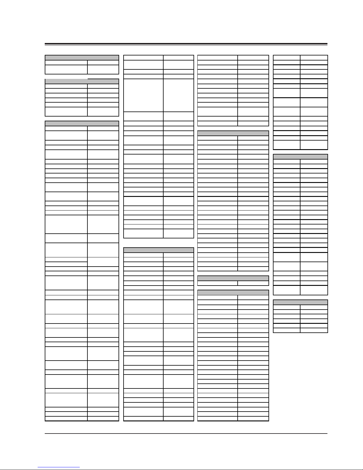
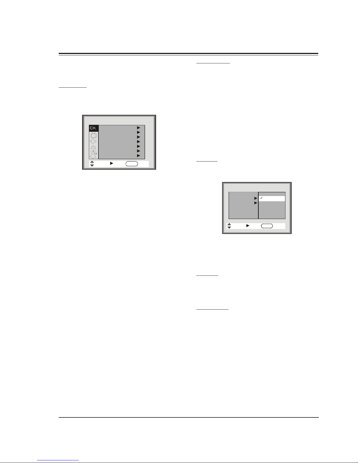
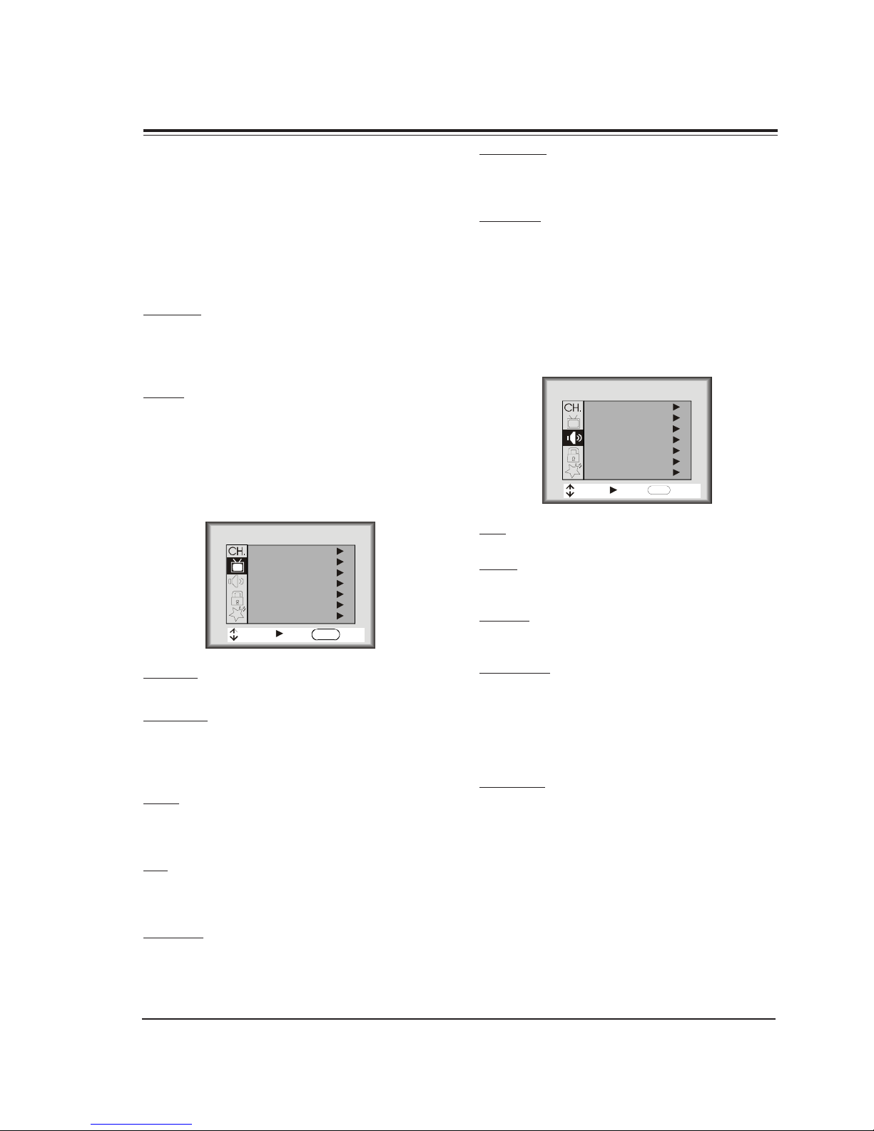
LG RP-29FA40-M User manual

website:http://biz.LGservice.com
E-mail:http://www.LGEservice.com/techsup.html
COLOR TV
SERVICE MANUAL
CHASSIS : FA
MODEL : RP-29FA40-M
RP-29FA40-O
RP-29FA40-P
RP-29FA40-R
CAUTION
BEFORE SERVICING THE CHASSIS,
READ THE SAFETY PRECAUTIONS IN THIS MANUAL.

OVERVIEW
1-1 FA - GENERAL
The FA chassis was developed for consumer market pur-
pose. This manual covers 27v True Flat CRT only. The
chassis is divided in two sections, the large signal board
is containing the deflection, dynamic focus, power sup-
ply circuitry & shutdown circuit. A second board, lo-
cated on the left side of the figure, is employed for
processing the RF, audio, communication (main BUS),
deflection, IF and video signals, this chassis does not
require any other daughter board.
The Analog Flat chassis features a total of 9 IC’s on the
small signal board, for RGB signal, video switching, (HV
sync signal processing included). This chassis only sup-
ports the NTSC-U (USA) video format and this is made
trough the IC2200, P221-01519, main video processor
located on the middle of the small signal board, which is
taking care of the IF, AGC, OSD switching, YUV process-
ing, Automatic Contrast Level Control Systems, SVM sup-
port, Audio/ Video & Chorma demodulation, including
Horizontal (East/West correction & X-ray protection) and
Vertical deflection signals. The IF signal come from the
WT1201, which is the main tuner.
A relationship between IC2200 and IC2990, P221-01438,
is linked, this last one is used for switching the video
signal inputs from the Front and Rear jacks. Also in-
volved is the digital comb filter IC2400, 221-01449,
which is used to separate the Y and C signals from any
composite video (RF or Video In). The YUV input is pro-
cessing directly through the IC2200.
The audio channels are applied to the audio processor
IC1400, 221-01127. The IC1400 is also processing the
TV- RF composite audio, this IC features function such
audio demodulation, SAP (second audio program), and
the audio processing for BASS, TREBLE and BALANCE ad-
justments, also includes the Surround and Soundrite fea-
tures.
Once the audio is processed by IC1400, both channels
are applied to the main stereo amplifier. The IC800, P221-
1488, is the final audio stage and its signal is applied
to the speakers.
CON2K6
AK
AK
SVM COIL
Interconnect Diagram

OVERVIEW
FA - GENERAL 1-2
The IC6000 is the 8 bits & 80K microcontroller and the
IC6001, 221-00745-05, is the EAROM memory. The
IC6000 handles the communication thru IIC BUS, I/O
ports, ADC converters for the keyboard, also supplies the
OSD signals for the On screen menus and the Close Cap-
tion decoding.
The main board is using three main linear regulators for
providing several voltage sources, the ICX3821 [5VSW]
for Tuner and IC2200 , ICX3820 [5VSB] for the IC6000/
1 and ICX3822 [9VSW] for most of the rest of IC’s. The
VSW stand for SWITCHED VOLTAGE, these regulators con-
tain an internal power switch to turn them on/off, from
a Power Control signal provided by the IC6000.
Finally the main board has a provision for an additional
IC, for switching the YUV inputs. The objective of this
IC2902 is for adding an extra YUV input. This circuit
will be available for a future model.
On the large signal module there are five IC’s , the ICX3612
is the main power switching and PWM hybrid circuit and
in conjunction with ICX3702 made the main power regu-
lation of this chassis. The purpose of this regulator is to
provide a proper protection for avoiding to shut the
main power supply off and therefore the complete TV set.
And of course, avoid the necessity of fuse replacement
due to a short circuit on the third party TV card.
The ICX2100 is the Vertical output amplifier and is pro-
cessing the small signal provided by the IC2200 on the
small signal board. Also the IC3300 is processing the
EAST/WEST correction for the screen geometry.
Finally The IC5100 is used to amplify the RGB small sig-
nals from the IC2200 and then display them on the CRT
cathodes.
S-VIDEO OUT S-VIDEO IN
RPr Pb
L
ANTENNA
CAB LE
VIDEO IN
YR AUDIO IN L
R AUDIO IN L
MATRIX OUT
COMPONENT VIDEO I NPUT
R AUDIO IN L
MODEL SCR CABINET F. JACKS R. JACKS EXTRA FEATURES REMOTE MICRO OP GUIDE
RP-29FA40-M 29 Table Top 4 13 TRUE FLAT, YUV INPUTS, AUTOVOLT 124-00233-P09 P221-01524-00 P206-04552
RP-29FA40-P 29 Table Top 4 13 TRUE FLAT, YUV INPUTS, AUTOVOLT 124-00233-P09 P221-01524-00 P206-04552
RP-29FA40-O 29 Table Top 4 13 TRUE FLAT, YUV INPUTS, AUTOVOLT 124-00233-P09 P221-01524-00 P206-04552
RP-29FA40-R 29 Table Top 4 13 TRUE FLAT, YUV INPUTS, AUTOVOLT 124-00233-P09 P221-01524-00 P206-04552
FA Chassis Model Information
ALL MODELS ARE MODULE LEVEL REPAIR

1-3 FA - REMOTES
MBR3447LG MODEL REMOTE CONTROL
PROGRAMMING THE REMOTE
If you’re using Zenith products, the remote is already pro-
grammed for most common codes: TV= 101, VCR= 201,
CABLE=353, and AUX=401. For other brands, or if your
remote fails to control your Zenith products, you’ll have
to program the remote.
After installing the batteries, follow these steps for each
product:
1. Press and hold PRG using a blunt pointed object.
Release PRG after the indicator light turns on.
2. Press the device button to be programmed (CATV,
VCR, AUX, or TV).
3. Enter the 3-digit product code from chart on the
next page.
4. Press and release ENTER to save the code.
5. Point the remote at product and press POWER to
test the product’s operation. If it does not turn on,
reprogram remote using a different code.
6. Write the code on the label inside the battery
compartment for future reference.
FLASHBK (Flashback)
Returns to previous Channel.
POWER
Turns TV On or Off.
MODE
Selects the remote's mode of operation
MUTE
Turns sound Off and On
while picture remains.
VOLUME (Left/Right)
Increases TV’s sound level.
ENTER
Shows Channel/Time, enters
channel, or removes any
on-screen menus.
UP and DOWN ARROWS
Moves highlighted bar within
menu to select an option.
CC
Displays closed caption menu.
TV/VCR SOURCE
Steps through source options.
SURF
Turns Channel Preview On/Off.
When on, the Channel Up/Down
keys only Scroll through channels
selected in the Add/Del/Blnk.
CHANNEL (Up/Down)
Selects next channel in
TV’s memory. Press
and hold to repeat.
NUMBER PAD
Selects channels directly.
MENU
Displays menus for TV
and other options.
LEFT/RIGHT ARROWS
Chooses and shows the
desired menu option.
A, B, C Keys
In commercial TV’s, doesn’t
have functionallity.
TIMER
Displays the Sleep Timer menu.
Press repeatedly to set desired
TV shut-off time.
QUIT/ (Three Functions Key)
It doesn’t function in commercial TV.
MBR3447LG
124-00233-P09

FA - REMOTES 1-4
AUTO FIND
If none of the codes in the code table operate your equip-
ment, use Auto Find to search for the proper code.
1. Turn on the product you want to operate.
2. Press and hold PRG using a blunt pointed object.
Release PRG after the indicator ligth turns on.
3. Press any key to be programmed (CAT, VCR, AUX, or TV).
4. Enter ”000”, then press ENTER within two seconds.
Auto Find is active after the indicator light flashes
and remains lit.
5. Point the remote at the product.
6. Press and release POWER repeatedly, about once a
second, until your products turns off. The indicator
light turns off when you press POWER and on when
you release it.
7. Press ENTER immediately to save the code. The
indicator light flashes to indicate the code has been
saved.
8. Press POWER to turn On your product.
9. Test your product. If the remote fails to operate
some of the basic functions, use Auto Find again to
search for a better code. (Auto Find resumes its
search after the last code that was entered and
saved in step 7).
NOTE: If the indicator light stays on as you press POWER,
Auto Find has tried all of the codes. If the product
you want to control has not turned off, your
remote will not work with that product. To cancel
Auto Find, press PRG at any time during Auto
Find.
CABLE BOX
This remote can control the cable/converter box volume
and muting (instead of the TV’s) is available on your
equipment.
1. Program the cable/coverter box normally.
2. After programming the cable/converter box. Press
and hold PRG again using a blunt pointed object.
Release PRG after the indicator light turns on.
3. Press and release the device button the cable box is
assigned to.
4.This time, enter the special code 3-9-9 instead of
the product code.
5. Press and release ENTER to save.
VOLUME OVERRIDE
These remotes can override TV, VCR, or Video Disk
Player volume functions with an amplifier’s volume and
muting.
1. Program the amplifier normally.
2. After programming the amplifier, Press and hold PRG
again using a blunt pointed object. Release PRG
after the indicator light turns on.
3. Press and release the device button whose volume
control is to be replaced by the amplifier volume
control. For example, pressing TV will operate the
amplifier’s volume while the remote is in TV mode.
4. This time, enter the special code 4-9-9 instead of
the product code.
5. Press and release ENTER to save.
AUXILIARY CAPABILITY
This remote can control up to seven devices. If the
remote has been programmed for four components
using the TV, VCR, CABLE, and AUX keys, you may also
program it for up to three additional using AUX+1,
AUX+2 and AUX+3
To Program AUX+1, AUX+2 AND AUX+3
1. Locate three digit code for product in code table.
2. Press and hold PRG until indicator lights up
3. Press the AUX and 1 simultaneously to select
AUX+1.
4. Enter the three-digit code and press ENTER. The
indicator light should flash and then turn off to
indicate the code has been accepted. If the light
stays on, repeat steps 3 and 4 or try a different
code.
5. Repeat steps 2-4 for AUX+2 and AUX+3.
6. Write the codes on the labels inside battery
compartment for future reference. Hold down AUX
and press 1,2 or 3 to access AUX+1, +2 or +3
mode.
UNIVERSAL ERASER 911
To restore the transmitter back to its initial default
settings, enter the Programming Mode as usual (by
holding PRG until the LED indicator lights), and press 9
1 1, followed by ENTER. The LED indicator will flash
three times to indicate that the transmitter has
returned to its initial default brand codes. Universal
Erase will work in any mode.
REMOTE PROGRAMMING

PROGRAMMING CODES
FA - REMOTES 1-5
TV's Portland 246,727 SL Marx 326 Sears 936
Daewoo 149 ProScan 216,260,266, Sprucer 313 Sharp 441,442
Zenith 101,121,149 282,725 Stargate 326,379 Sherwood 449
152 Quasar 259,295 Standard Comp 335 Hitachi 950
Radio Shack 213,265,730 Teleview 326 JVC 949,954
TV/VCR RCA 216,220,228, Texscan 339,356,371 Kenwood 441,931,948
A
dventura TV/VCR 154 240,242,249, Tocom 317,318,346 Luxman 930
Daewoo TV/VCR 148 260,266,282, Unika 325,348,362 Magnavox 421,422,433,
Funai TV/VCR 154 283,284,285, Universal 325,358,362 434
Goldstar TV/VCR 153,172 286,287,288, Vid Tech 340 Son
y
420,443,444,
Symphonic TV/VCR 154 708,710,711, Video Way 349 445,934
Zenith TV/VCR 150,153,154 725 Viewstar 327,354,355, Soundesign 461,498,901,
172 Realistic 212,213,265, 372 902
730 Zenith HT-2000 353 Sylvania 433
VCR's Saisho 722 Zenith PM 374 Teac 418,419
A
dmiral 261 Salora 297 Technics 432
Akai 292,717,718, Samsung 220,230 SATELLITE Yamaha 414,941,942
719,720 Sansui 289,292,709,
A
lphastar 516 Zenith CD Reco
r
415
A
udio Dynamics 726 726 Chaparral 501,502 Zenith 460,461,498,
Bell + Howell 247 Sanyo 212,247,294 Cheyenne 502 901,902
Broksonic 221,250,255, Scott 243,290,729 Dishnet 515
729 Sears 211,212,213, Drake 503 TUNER/AMP
Candle 727 265,274 GE 510,517 Citizen 914
Canon 704 Sharp 261,730 General Instruments 504,505 GE 916
Capeheart 728 Signature 2000 216,219,249 Hitachi 519,520 Goldstar 460,474
Citizen 727 Sony 232,723,724 Hughes Network 514 Hitachi 919
Craig 212 Sylvania 275,297 JVC 518 JVC 908
Curtis Mathes 259,266,725, Tatung 268,292 Macom 314 Kenwood 484
727 Teac 268 Magnavox 521 Luxman 467
Daewoo 244,246,248, Teknika 272 Philips 521 Marantz 903,913
254,703,729 Toshiba 213,274,290, PrimeStar 513 Memorex 485
Daytron 246 297 ProScan 510,517 Nad 904
DBX 726 Vector Research 726,727 RCA DSS 373 Nakamichi 493
Electrohome 730 Victor 726 RCA 510,517 Onkyo 471,906
Emerson 203,221,243, Video Concepts 726,727 Realistic 506 Optimus 905
250,293,721, XR - 1000 243 Sierra I 502 Panasonic 912
722,729,730, Yamaha 726 Sierra II 502 Pioneer 470,485,907
731,732 Zenith 201,224,225, Sierra III 502 Proton 910
Fisher 211,212,213, 229 Sony 511 Quasar 912
247,265,274 STS1 507 RCA 909
GE 216,220,266, STS3 508 Sharp 483,917,918
282,701,702, CATV Toshiba 509,512 Sherwood 900
725
A
llegro 358,362 Uniden 522 Son
y
486,489,490,
Go Video 256,262,263,
A
llegro A-B Switch 361 United 344 491,492
700
A
rcher 325 Zenith Drake 312,328,330 Soundesign 461,498,901,
Goldstar 253 Century 325 Zenith 351,378,500 902
Harman Kardon 296 Citizen 325 Toshiba 915
Hitachi 257,270,273, Comtronic 326 AUDIO - TAPE DECKS Technics 912
292,705,706, Everquest 379 Sony 452 Victor 908
707,708 Garrard 325 Zenith 460,461,498,
JC Penney 268,726 GE 367 COMPACT DISC 901,902
Jensen 292 Gemini 305,331,338
A
DC 940
JVC 224,225,258, General Instrument 304,305,306, ADO 939 DVD Players
268,292,299, 307,308,309,
A
iwa 938 JVC 965
726 310,318
A
kai 937 Mitsubishi 964
Kenwood 268,292,726, Hamlin 302,303,345, Denon 935 Pioneer 963
727 365,366 Dynatech 953 Son
y
962
Magnavox 275 Jasco 325 Emerson 952 Toshiba 961
Marantz 267,268,726, Jerrold 304,307,308, Fisher 438,933,951 Zenith 960
727 309,310,318, GE 932
Memore
x
212,298 360,363 Goldstar 460
MGA 297,730 Kale Vision 335 Hitachi 950
Mitsubishi 276,277,278, Macom 321 Kenwood 441, 931, 948
279,280,296, Magnavox 327,334 JVC 949, 954
297,730 NSC 335,339,368, Luxman 930
Montgomery Ward 216,219,249, 369,370 Marantz 929,947
291,730 Oak 311,332,342 MCS 928
Multitech 727 Panasonic 313,320 Mitsubishi 927
NEC 267,268,269, Philips 325,327,347, Nakamichi 925,926
281,292,709, 350,352,354, Onkyo 923,924,946
726 355 Optimus 920,921,922
Orion 250 Pioneer 315,343 Panasonic 431,432,945
Panasonic 245,251,259, RCA 341 Philips 421,433,434
713,714,715, Regency 329 Pioneer 431,435,944
716 Samsung 326,335 Quasar 432
Penta
x
708,727 Scientific Atlanta 316,323,336, Radio Shack 431,441
Philco 275 337,364 RCA 437,943
Pioneer 210,282,726 Signal 326 Sanyo 438,439

1-6 FA - MENUS
USER MENUS P221-01524-00
CHANNEL MENU
Below is the Channel Menu for the FA chassis with each
of its options.
EZ PROGRAM
The EZ Program feature automatically searches for all avail-
able channels and marks them as ‘Added’ so that they
may be accessed via the channel Up/Down key.
MOVE NEXT EXIT
EZ Program
Add/Del/Surf
EZ Clock
Captions
Caption/T
ext
Language
Source
CHANNEL
ENTER
In the EZ Program option, the current RF input type (Off
Air Antenna or Cable TV) is highlighted. Use the Up/
Down Arrow keys to change the RF input type.
To start the EZ Program, press the Right Arrow key. If the
Cable TV input type is selected, the EZ Program routine
will determine what type of cable system is present.
Notes:
• EZ Program clears all Surfing channels, which were
added.
• While searching for channels, all keys except for the
Power key are disabled. This prevents an incomplete
EZ Program procedure.
• Running the Auto Program will clear the factory mode,
if it was active. This happens at the end of the EZ
Program.
• If the EZ Program line in the Setup Menu is ‘red’, this
indicates that the module did not pass by Chassis.
When ‘green’, this indicates that the module did not
pass by Tracking. When ‘blue’, this indicates that the
module did not pass by Programming. To clear this
line to ‘white’, set the upper nibble of the EEPROM
location $1FFh to $B0h.
• If no channels are found then the following message
will appear: “Make sure that the cable/ant. is
connected, and try again.”
ADD/DEL/SURF
After running the Auto Program, all channels found by
the Auto Program feature will be marked ‘Added’. How-
ever, some of these channels may be scrambled, or un-
desired by the customer. The Add/Del/Surf feature al-
lows the customer to selectively mark any channel as
‘Deleted’ or ‘Added’.
To change the status of a channel, press the Up/Down
Arrow keys.
To change the channel while adding or deleting chan-
nels, use the Channel Up/Down keys, or press the de-
sired channel digits, followed by the ENTER key. If only
one channel is present, to change the channel the cus-
tomer must use the digit keypad to select a channel.
EZ CLOCK
When the EZ Clock item is selected, pressing the Right
Arrow key allows entry into the clock set menu.
Clock Mode
Time Set
Manual
Auto
CLOCK
Manual
MOVEMOVE NEXTNEXT BACKBACK
ENTERENTER
DAYLIGHT SAVINGS TIME
The customer also has the option of selecting the Day-
light Savings Time to be On, Off or Auto using the Left/
Right Arrow keys.
CAPTIONS
This feature allows the customer to select: Off, On, or EZ
when Muted options.
To change the status of captions, press the Left/Right
Arrow key to select either On, Off, or EZ Mute.
CAPTION/TEXT
This feature allows the customer to activate or
desactivate Captions or Text.
Pressing the Left/Right Arrow keys sequentially through
each of the following Caption/Text options.
Caption 1 Caption 2 Caption 3 Caption 4
Text 1 Text 2 Text 3 Text 4

1-7 FA - MENUS
USER MENUS P221-01524-00 (continued)
Notes:
• When the Text option is selected and a text box
appears, if the CC key is pressed, the Caption box
that allows setting to On, EZ Mute or Off will appear,
• When captions are being displayed, if one of the
Volume Up/Down keys is pressed, the volume bar will
not appear.
• When the Captions are not activated and the CC key
is pressed, the Caption Box will appear, that allows
choose On, EZ Mute or Off.
LANGUAGE
This feature allows the customer to change the menu
language to English, Spanish or French by pressing the
Up/Down Arrow keys.
SOURCE
This feature allows the customer to select: Antenna, Rear
Video, Rear-SV, Front Video, or Comp. Video.
PICTURE MENU
All menu items are adjusted with the Left/Right Arrow
keys.
Contrast
Brightness
Color
Tint
Sharpness
Color Temp
EZ Picture
PICTURE
MOVE NEXT EXIT
ENTER
CONTRAST
Contrast adjustment has 101 steps (0 to 100).
BRIGHTNESS
The brightness value sent to the video processor is (RfBrt
+ Customer Brightness) if the source is the RF source, or
(AuxBrt + Customer Brightness) if the source is the AUX
source. RfBrt and AuxBrt appears in the factory menu.
COLOR
Color adjustment has 101 steps (0 to 100). The color
value sent to the video processor is according to the
next equation and look up table.
TINT
Tint Adjustment has 101 steps (0 to 100). A center
mark indicates step 50. The tint value sent to the video
processor is (custom Tint + TintOffset)*127
SHARPNESS
Sharpness adjustment has 101 steps (0 to 100).The sharp-
ness value is sent to the video processor as (Custom
Sharpness).
COLOR TEMP
Sets the color temperature. The two settings are COOL
and WARM.
EZ PICTURE
This feature allows the customer to maintain 8 separate
Contrasts, Brightness, Color, Tint, Sharpness by setting
“Custom, Normal, Movie, Digital, Video Game, Sports,
Night Time, Weak Signal”.
SOUND MENU
All menu items are adjustment with the Left/Right Arrow
keys.
Bass
Treble
Balance
Audio mode
Front Surr
EZ Soundrite
EZ Sound
SOUND
MOVE NEXT EXIT
ENTER
BASS
Bass adjustment has 101 steps (0 to 100).
TREBLE
Treble adjustment has 15 steps (0 to 14).
BALANCE
Balance adjustment has 29 steps (0 to 28).
AUDIO MODE
There are three audio modes available: Mono, Stereo, 2nd
Audio/SAP.
If 2nd Audio/SAP is selected, but the current channel
does not support SAP, then either Stereo or Mono will
be heard.
FRONT SURR
Front Surround can be set ‘ON’ or ‘Off’, regardless of the
current Audio Mode setting. However, the Front Sur-
round effect can only be heard when the Audio Mode
has been set to ‘Stereo’ and a Stereo signal is present.
When this condition exists, there will be a short mute
(200ms) while toggling the Surround ‘On’ to ‘Off’, to
embellish Front Surround activation.

USER MENUS P221-01524-00 (continued)
FA - MENUS 1-8
EZ SOUNDRITE
The Sound Rite feature is used to obtain a uniform vol-
ume level, particularly while changing channels. The
Sound Rite feature can be best demonstrated on a chan-
nel with no signal (snow).
EZ SOUND
The EZ Sound Control has six selections the customer
can select. The selections available are: Custom, Normal,
Stadium, News, Music and Theater. The Left/Right Arrow
keys may be used to select any of the choices mentioned.
LOCK MENU
As show above, with the Lock Menu on-screen, use the
Up/Down arrow to highlight an option Like Content Blk,
then press ENTER.
Use the Up/Down/Left/Right arrows to select and ad-
just or set the rating for an option. For Sex Scenes for
example , use the “From TV-PG” setting. (See the Mini
Glossary, Ratings Charts on this and the previous page
for rating definitions).
Aux Sources
MPAA
Age Block
Content Blk
Cdn. Ratings
Set Hours
Set Password
Lock On/Off
LOCK
MOVE NEXT EXIT
ENTER
AUX SOURCES
To Block or Unblock the sources, press the Up/Down Ar-
row keys.
The SOURCE key may be used to view the other source.
MPAA
The MPAA selector allows the customer to select either
to have the channel Unblocked, G and Above, PG and
Above, PG-13 and Above, R and Above, NC-17 and Above,
or X.
AGE BLOCK
Use the Right Arrow key to select the Age Block Menu.
Once entered into the Age Block Menu, the customer
has the option to block channels for general age or to
block channels for children.
GENERAL BLOCK
To block channels for a general age, the customer may
either select: Unblocked, TV-G and Above, TV-PG and
Above, TV-14 and Above or TV-MA.
General
Unblocked
TV-G
TV-PG
TV-14
TV-MA
AGE
Children
General
MOVE NEXT BACK
ENTER
CHILDREN BLOCK
To block channels for children, select either: Unblocked,
TV-Y and Above or TV-Y7.
CONTENT BLOCK
To block a television program according to its content,
use the Right Arrow key to select the Content Block Menu.
General
Unblocked
TV-PG
TV-14
CONTENT
Language
Violence
Sex Scenes
F Violence
No Rating
Dialog
MOVE NEXT BACK
ENTER
DIALOG BLOCK
To block a television program with Dialog rating, use the
Up/Down Arrow keys to select either: Unblocked, TV-PG
and Above or TV-14.
LANGUAGE BLOCK
To block a television program with Language rating, use
the Up/Down Arrow keys to select either: Unblocked,
TV-PG and Above, TV-14 and Above, or TV-MA.
VIOLENCE BLOCK
To block a television program with Violence rating, use
the Up/Down Arrow keys to select either: Unblocked,
TV-PG and Above, TV-14 and Above, or TV-MA.
SEX SCENES BLOCK
To block a television program with Sex Scenes rating,
use the Up/Down Arrow keys to select either: Unblocked,
TV-PG and Above, TV-14 and Above, or TV-MA.

1-9 FA - MENUS
USER MENUS P221-01524-00 (continued)
F VIOLENCE BLOCK
To block a television program with F Violence rating, use
the Up/Down Arrow keys to select either: Unblocked,
TV-Y7.
NO RATING BLOCK
To block a television program with No Rating , use the
Up/Down Arrow keys to select either: Unblocked and
Blocked.
CANADIAN RATINGS
Use the Right Arrow key to select the Content Block,
and use the Left/Right Arrow keys to select the Cnd.
English or Cdn. French.
General
Exempt
Children
8+
General
PG
14+
18+
CDN. RATINGS
Cd. French
Cdn. English
MOVE NEXT BACK
ENTER
SET HOURS
Use the Up/Down Arrow keys to adjust the number of
hours the Parental Control feature will be active. The
valid hour range is 1 through 99 hours.
SET PASSWORD
Press the Right Arrow key to allow Password entry.
TO ENTER PASSWORD
The software accepts four-digit codes only. The cus-
tomer must enter a password
REPEAT PASSWORD
After a four-digit code has been entered, the software
requires the customer to re-enter the same four-digit
code.
PASSWORD NOT ACCEPTED!
If an invalid code is entered, or the two codes entered
do not match, a blinking error message (“Not Accepted!”)
will appear. This error message also appears when no code
is entered for the password or if only one digit is en-
tered and no other digit has been entered.
LOCK ON/OFF
This item turns the Parental feature On or Off. The Pa-
rental Ctrl. feature can only be turned on if the hours >
0, and a password has been set. Otherwise the Lock On/
Off line will display either of the following error mes-
sages: “Must Set Hours” or “Must Set Password.”
RE-ENTERING PARENTAL CONTROL MENU
If the Parental Control feature has been activated,
the software will not allow immediately entry into
the Parental Control Menu. Instead, it will prompt
for the correct password. If the correct pass-
word is entered, the Parental Control menu will
be unlocked so the user can change the con-
figuration for parental options. If an incorrect
password is entered, an error message (“Not Ac-
cepted!) appears, and will not disappear until 5
seconds. This extended time provision increases
the amount of time necessary for a child to “crack”
the password.
Notes:
• The Parental Control menu will remain up for
15 seconds after the last key press.
• The QUIT key may be pressed to remove the PC
menu.
• Entry into the Factory Menu will immediately
turn off the PC feature
• The PC Hours and Password will be cleared
upon exit of the Parental Ctrl menu (unless
the Parental Ctrl feature has been turned on.)
DISPLAY WHEN PARENTAL CONTROL IS ACTIVE
When the Parental Control has been activated
the channel is blocked. The display on the screen
shows two lines. The first line displays a mes-
sage saying that the “PARENTAL LOCKOUT IS AC-
TIVE.”
The second line displays the amount of time (in
hours) left in the lockout.

USER MENUS P221-01524-00 (continued)
FA - MENUS 1-10
SPECIAL MENU
This Menu contains the EZ Timer , Ch. Labels, XDS Dis-
play, EZ Demo and EZ Help.
EZ Timer
CH. Labels
XDS Display
EZ Demo
EZ Help
SPECIAL
MOVE NEXT EXIT
ENTER
EZ TIMER
The Timer Menu contains the Sleep Timer and the On/Off
Timer features.
SLEEP TIMER
Sleep Timer (via Timer Menu)
The Left/Right Arrows can be used to adjust the current
sleep timer setting:
Off, 0:10, 0:20, 0:30, 1:00, 1:30, 2:00, 3:00 or 4:00
EZ Timer
CH. Labels
XDS Display
EZ Demo
EZ Help
PRESS
TO SET
SPECIAL
MOVE NEXT BACK
EZ Timer
ON/OFF TIMER
This feature consists of three menu lines: “On Time”,
“Off Time”, and “On/Off Timer”. This feature allows the
set to turn on and off at the times specified in “On
Time” and “Off Time”.
The “On Time” and “Off Time” are set identical to the
Clock Set feature in the Channel Menu.
An Off Time must be specified, before turning on the “EZ
Timer”—otherwise an error message (“Must Set On/Off”)
will be displayed on the On/Off Timer line.
The On/ Off Timer option turns the Timer On or Off.
If there is no Off Time set, then the On/Off Timer dis-
plays the above message saying: “Must Set Off Timer.”
Once the Off timer has been set, the customer can then
set the option to either On or Off.
CHANNEL LABELS OPTION
This feature allows the customer to select a channel la-
bel for the current station. This channel label is dis-
played in the Channel/Time display. Initially, all channel
labels are set to ‘——‘, which results in no channel be-
ing displayed in the Channel/Time display.
A&E CMTV ESPN HSE NOS TBN VC
AB
C
CNCB ESP2 HSN PBS TELE VCR
ACTS CNN E
T
IC PLA
Y
TL
C
VH-1
AD
C
COM EWTN INSP PT
L
TM
C
VISN
AMC CSPN FAM JCN QV
C
TNN VJN
BCC CSP2 FNN LIFE RDS TNT WB
BET CTN FO
X
MAX REQ TRAV WGN
BRAV CTV F&V ME/U S
C
TSN WTBS
CA DIS F
X
MM
T
SCFI TVA WWOR
CBC DIS
C
GALA MTV SHOW TWC YTV
CBN E! HBO NB
C
SIN UPN ----
CBS EN
C
HN NICK TBS USA None
CHANNEL LABELS
To change the current channel label, press the Up/Down
Arrow key.
To change the channel while adjusting channel labels,
use the Channel Up/Down keys, or press the desired chan-
nel digits, followed by ‘Enter’. (If Channel Up/Down is
pressed, the next or previous channel which was marked
‘Added’ will appear.)
Note:
• When in the channel label is selected ————, then
the Auto channel label is activated, in other words,
the program automatically take the channel label
of the signal that is send by broadcasting through
the XDS service.
• If the label None is selected, the Auto channel label
is disactivated.
XDS DISPLAY
Pressing the Left/Right Arrow Keys allows the customer
to select the XDS Display either On or Off.

1-11 FA - MENUS
USER MENUS P221-01524-00 (continued)
EZ DEMO
The EZ Demo is designed to show-off the icon menus
and other icon displays on the sales floor. The EZ Demo
feature can be turned On/Off with the Up/Down Arrow
keys.
Initially, when the feature is activated, as soon as the
OSD times out, the EZ Demo will start. At this point,
pressing any key will temporarily disable the EZ Demo for
18 seconds, and if the EZ Demo is working and the Menu
key is pressed then the Special Menu will be displayed
and the EZ Demo feature will be selected allowing the
customer to disable it.
Note:
• The Auto Demo On/Off setting is not stored to the
EEPROM.
EZ HELP
The special features EZ Help option may be accessed us-
ing the Right Arrow key. The EZ Help feature provides
help on certain options and also provides support for
the EZ Programm, Add/Surf/Del, Degaussing, EZ Picture
and EZ SoundRite features. There is a simple explanation
of each options.
The EZ Help has a main screen called EZ Help. This screen
gives a solution to the most common problems that a
customer may encounter; i.e., To program channels.
MISC DISPLAYS
SLEEP TIMER
To press the timer key for activate the sleep timer.
The user can choose to activate the timer to turn off the
Television in 10, 20 or 30 minutes or 1, 1:30, 2,3 or 4
hours just by clicking on the sleep timer clock.
VOLUME DISPLAY
When the Volume key is pressed, the following display
appears on the screen.
23
CLOSED CAPTIONS
If the CC key is pressed the following displays appears.
The customer may change the settings of the Closed Cap-
tions to Off, On or EZMute
CHANNEL/TIME/AUDIO DISPLAY
Pressing the ENTER Key allows the customer to display
the channel, time audio mode as well as information of
the current program along with the rating of the pro-
gram.
OFF

FACTORY MENU
2-1 FA - INSTALLERS MENU
INSTALLERS MENU
Access the Installer’s Menu by using the remote control
or the keyboard on the front of the set.
With the remote: Press & Hold MENU key until the
Channel/Time display appears, then press 9, 8, 7, 6, and
ENTER.
With 6 button keyboard: Press and hold MENU until the
Channel/Time display appears. Simultaneously press the
VOLUME UP and CHANNEL DOWN keys.
Notes:
•When the factory mode is set to “1”, then
press ‘9’, ‘8’, ‘7’, and ‘6’, followed by
‘ENTER’ to access the Installer’s Menu.
•To acces the G2 re-adjustment mode, press 2 hold
the Menu key until the Channel/Time display appears,
then press ‘9’, ‘8’, ‘7’, ‘6’, and quit key.
00 Fact Menu: Use the Select key to select item #00,
which is the first item in the Installer’s Menu. The
Factory Mode item should always be left off (Zero is
off). When left in this mode, only items from 0 to 27
are visible. When the factory mode is set to 1, all menu
(Audio or Video settings) items will be available. Also
they will appear on the screen one at a time at the top
left of the screen.
When The Factory Mode is on, the Factory Menu line
appears at the middle of the screen to allow for proper
setting of the video.
When the Factory Mode is turned off, all TV functions
are returned to normal. The simbols at the top of the
channel menu icons is removed indicating that the
Factory Mode is off. There are 4 ways to turn off the
Factory Mode:
1. Change Installer’s Menu Item “00 F Mode” to 0.
2. Run Auto Program.
3. Use the Clock Set feature to set the time.
4. Use Factory off IR code.
Notes:
•Video Preference Settings Inhibited:In the Video
Menu, the Custom Video Preference settings are
inhibited while the Factory Mode is on and will
NOT be stored in EEPROM. (This allows the factory
to temporarily change the settings and not store
them permanently.)
01 Preset Px: Used to store the customer menu adjust-
ments in the nonvolatile memory of the EAROM. Set-
tings for Contrast, Brightness, Color and Tint are
stored in this manner. 0 is Custom and 1 is Preset.
02 Preset Ax: Saves your custom audio settings
(Bass,treble,balance,audio mode,sound rite,front
surr,speaker) in nonvolatile memory (not affected by
power loss). Memory status is indicated by a 1 for
“custom settings already stored”, or 0 for “custom set-
tings have not been stored.”
03 Vert Pos: Sets On Scree Display vertical position. Use
the ADJUST keys.
04 Horz Pos: Sets On Screen Display horizontal position.
Use the ADJUST keys.
05 Band/Afc: There are 8 possible settings for this op-
tion.
06 Ac on: Allows the TV to turn ON just by applying AC
power. Pressing the ON button is not necessary. This
is desirable when the TV is plugged into a cable box
or a power outlet controlled by a wall switch. Use ad-
just to select 0 or 1, where 0 is OFF and 1 is ON.
Note: When set to 1 (ON), the TV does not respond to
ON/OFF commands from either the remote or the
control panel, and the SLEEP TIMER is also
nonfunctional.
07 Feature Level: Set to 1 to see Zenith Code, when set
to 0 Private Codes are shown.
08 Trap: Turn On 3.58 MHz internal trap in Video Proces-
sor.
09 RF Band Pass Activates the Band Pass Filter for RF
(Antenna) input
10 RF BRT Set Black Level for RF input (Antenna)
11 Aux BRT Set Black Level for Auxiliar input (Video:
Composite & Y/C)
12Yuv BRT Set Black Level for YUV input (Component
Video)
13Max Bright Set maximum internal Brightness Register
14Max Contrast Set maximum internal Contrast Register
15 Vert Size: Vertical amplitude adjustment Variable in
factory menu. Range: 0-127, Initial value: 63.
16 Horz Size: Horizontal amplitude adjustment Variable
in factory menu. Range: 0-63, Initial value: 31.
17 Vert Phase: Adjust the Vertical Phase, screen up -
down. Range 0-5. Initial value: 0
18 Horz Phase: Adjust the Horizontal Phase, screen left-
right. Range: 0-31. Initial value: 32
19 Audio Level: Adjust the composite audio level aoutput
of the video processor.
20 RF AGC: Adjust the AGC delay for maximum gain with
a reference level of 0 dBmV.

FACTORY MENU (continued)
FA - INSTALLERS MENU 2-2
21 Horz AFC: Set the automatic horizontal frecuency con-
trol on, should be 1.
22 WPL: Activates White Peak Limiter
23 Tint Offset: Set the Tint offset
24Red Cut: Set the Red Cutoff of Low Luminance White
Balance adjustment
25Green Cut: Set the Green Cutoff of Low Luminance
White Balance adjustment
26Blue Cut: Set the Blue Cutoff of Low Luminance White
Balance adjustment
27Green Gain: Set the Green Gain of High Luminance
White Balance adjustment
28Blue Gain: Set the Blue Gain of High Luminance White
Balance adjustment
29Air AFT: Set the AFT when watching air signal.
30 A ATT: Adjust the composite input level to the audio
decoder to have the standard input level.
31 A VCO: Adjust Stereo VCO and SAP VCO free running
frequency.
32 A Filter: Adjust the filter for Stereo, SAP and DBX.
33 A Spectral: Adjust high frequency stereo separation
(3KHz.)
34 Wide Band: Adjust low frequency stereo separation
(300Hz.)
35 Max Blk. Hrs: Adjust the maximun number of hours
the TV can remain Blocked (even 99 hours)
36RGB Contrast: Set OSD Contrast level
37SUB Contrast: Set internal Sub-Contrast Register
38 EW Correct: East- West Correction. Range 0-63, Ini-
tial value:26
39 EW Top-Corr East-West Corner Correction (top). Range
0-31, Initial value: 14
40 EW Bott-Corr: East-West Corner Correction (bottom).
Range 0-31, Initial value: 23
41 EW Trap-Corr: East-West Trapezium Correction.Range
0-63. Initial value 30. Range 0-31, Initial value: 23
42 V Centering: Vertical Centering. Range 0-63. Initial
value: 30
43 V Linearity: Vertical Linearity. Range 0-15. Initial
value: 12
44 V S-Corr: Vertical S-Correction. Range 0-15. Initial
value: 11
45 H EHT Comp: Horizontal Extremely High Tension
Compesation. Range 0-7. Initial value: 4
46 V EHT Comp: Vertical Extremely High Tension
Compesation. Range 0-7. Initial value: 6
47DC Rest Set the DC Restoration level
48BLK Stretch Set the Black Stretch start point
49ABL Gain Set the Automatic Black Level Gain
50SVM GAIN Adjust the Scan Velocity Modulator gain
51SVM PH Adjust the Scan Velocity Modulator Phase
52ACB SW Activates Automatic Control Beam
53SHARP PF Sharpness peak frequency selection: 0 to
3.2 MHz and 1 to 4.0 MHz
54CORING Activates the enhancement of Sharpness from
1 to 2 MHz
55B-Y ATT Set the attenuation level of Cb of YUV signal
56R-Y ATT Set the attenuation level of Cr of YUV signal
57AUTO FLESH Activates the Flesh tone control
58 ABL START POINT Set the Automatic Black Level Start
Point
59Y GAMMA Set the non-linear Gamma curve for Lumi-
nance signal
60ACB PULSE P Set Automatic Control Beam Start Point
61SCREEN Not used
62AKB SETUP Mute the RGB Cathodes
63AUX BAND PASS Activates the Band Pass Filter for
Auxiliar (Composite, Y/C, YUV) input
64CD MATRIX Set the relative phase and amplitude of
Color response to demodulate de Chroma
65YCbCr Select the Demodulation System for Component
Video YUV or YCbCr
66C GAMMA Switch the Color Gamma

3-1 FA - SERVICING
SERVICING
LARGE SIGNAL
POWER SUPPLY
The FA is a COLD chassis of a single sided circuit board,
developed for a 27”. The power supply section features
four IC’s for voltages sources. The FA chassis has the
capability to meet the Energy Star requirement for a
low power consumption on stand-by mode.
·9Volts, 1Amp ON/OFF Switch Regulator, 221-01460-07
·5Volts, 1Amp ON/OFF Switch Regulator, 221-01460-03
·5Volts, 0.150 Amp Switch Linear Regulator,
0IKE780500P
·Main regulator for Horizontal Deflection (B+), +15V,
Switch mode regulator 223-00061-01.
·Error amplifier 221-00265-03A.
B+
+VAUD
+16VSB
LINE
FILTER
SWIT CHING
HYBRID I C
RECTIFER
SECTION
OPTO
DEVICE PWR CTRL
+5VSBF
ST EREO
DECODER
SWITCH & VOL-
CTL
ST AUDI O
SW EEP
TRANSFORME
R
+V AUD@ 1400mA
+130V@900mA
HV
6.3Vrms
-14VSW
+35VSW
+12~14VSW
+9VSW
+9VSW@55m
A
VIDEO
PROCESSOR
+9VSW@120m
A
+5VSW@70m
A
MI CROPROCESSO
R
+5VSBF@27mA
TUNER
+33VSW
+33VSW@ 15m
A
+5VSW@100m
A
VERTICAL
DEFLECTION
-14VSW@
HORIZO NTAL
DRIV E
+15VSB@100mA
AC LINE
FILAMENT
6.3Vrms@315m
A
SHU NT
REGULATOR
+5VSB
MPI
(INTERFACE)
+5VSB@2mA
+5VSW
+9VSW@5m A
COMB FILTER
+5VSW@80m
A
+9VSW@50m
A
SWITCHER
CXA2089S
+9VSW@70m
A
+21VL
+12VSB@600mA
+14VSW@
205VSW
ABL
+12VUP
LSP
PROTECTION
SWITCH MODE REGULATOR
The FA chassis employs a switching power supply, quasi-
resonant topology type. The AC line is supplied thru
the bridge rectifier BRX3400 and CX3410 circuit through
the fuse FX3400 (5A @ 250 V fast blow), The AC opera-
tion range is between 90 Vrms to 135 Vrms (see TABLE
1.1) and a filter, consisting of LX3400, LX3401, CX3401,
CX3403 and CX3408, which is employed before the rec-
tifier circuit to reduce noise from the AC line and vice
versa (EMI).
The voltage output of the rectifier, VDC, is supplied to
the Switch Mode Regulator Power Supply, and its out-
put should be in this range [127 VDC to 352.5 VDC].
The SMPS consisting of ICX3612, ICX3701, ICX3702 and
the chopper transformer TX3600. Through 100 KOHM
resistor (Rst), RX3601 and CX3604 (Cst), which is de-
rived the VCC from CX3410. These feed the pin 3 into
the internal zener diode located within ICX3612.
POWER SUPPLY BLOCK SCHEMATIC

SERVICING (continued)
FA - SERVICING 3-2
At the same time this voltage is also applied to an inter-
nal comparator. So the voltage of this power source must
be within a set range, between a 5VDC reference (Vref)
and a 32VDC zener diode (Vz).
This set range is verified through the UVLO (Under Volt-
age Lock Out) circuit of the Switch Power IC.
START UP
When the VCC reaches a upper threshold voltage (15
VDC) the comparator switches to enable the ICX3612
including all internal bias circuits, control circuits, PWM
modulator & Power MOSFET.
Due the demand of energy from Cst and Rst the VCC volt-
age starts to fall. Before to fall too low, a bootstrap
winding on the power transformer (pins 13 & 16) reforces
adequately the VCC power to keep the full system opera-
tion.
VOLTAGE SOURCES
There are Five secondary windings on the TX3600 and
each has its own half wave rectifier.
Consequently there are Five stand-by DC voltages: B+,
24VAUD, 21VL, 16VSB & 12VUP.
The first is used to source the horizontal sweep circuit,
HOT (Horizontal Output Transistor). The second is used
for audio. The third is exclusively for the LSP source,
which is always on stand-by. The four is used for video
low signal processing and The fifth is used for
microcontroller.
The main microprocessor IC6000 and the EAROM memory
IC6001 are supplied by a five volts stand-by source,
+5V SB, which is derived through ICX3820 (0IKE78500P).
The +16 VSB and +12 VUP volts stand-by are protected
by fuses FX3613 and FX3614 ( 4A @ 125V) Very Fast
Acting, the +21VL and +24 VAUD volts stand-by are pro-
tected by fuses FX3611 and FX3612 ( 4A @ 125V) Slow
Blow. B+ as mentioned before are protected by the OCP
circuit. So they do not need fuse.
The FA chassis can be turn it on with the keyboard on
the front of the set or with the remote hand control.
The microcontroller IC6000 receive a signal and it out-
put a high, about 4.8V, on pin 32 which is called PWR-
CTL. This pin is connected to RX3832, RX3831 and
RX3540; producing the +VAUD, +9VSW, +5VSW.
DEGAUSSING
The FA chassis employs a new method of degaussing,
which is performed through software. The IC6000 gen-
erate a pulse of about 1 second, time fixed, on pin 43.
This pin is set to high, about 4.8 VDC, through R3900,
4.7K 5% ¼watt. And it applies to Q3900, which drives
the 12 VCD relay KX3900. So the degaussing is performed
when the degauss coil is plugged to CN3T8 connector.
POWER SUPPLY ALIGNMENT PROCEDURES
ELECTRICAL ADJUSTMENT
The FA chassis SMPS does not need any manual measure-
ment. All the output voltages are regulated through
ICX3702 (221-265-03A), error amplifier. The ICX3702
keeps the regulation using a reference voltage, through
a voltage divider. The voltage divider is formed by two
precision RX3706 and RX3704.
The values of these resistors depends of the B+ output
voltage.
NOTES:
·When servicing make sure to use a 120 VAC- 60Hz 25
Amp isolated source.
·Use a full white field on the video pattern generator.
PIN DESCRIPTION
PIN # DESCRIPTION FUNCTION
1 POWER MOSFET DRAIN To drive the chopper xfmr,capable of switching a max of 650V.
2GROUND
(HOT) MOSFET Source connection.
3DRIVE
(+VCC) Positive supply voltage, 32VDC
4 FEEDBACK (Vfb The output voltage error is applied to this pin.
5SYNCHRONY
(Vs/s External sync signal & Soft star capacitor.

3-3 FA - SERVICING
SERVICING
DEFLECTION
HORIZONTAL
PINCUSHION CORRECTION CIRCUIT
This circuitry provides a east/west pincushion correc-
tion by providing a smaller horizontal deflection current
at the upper and lower portions of the flat screen, thru
the dual OP-AMP IC3300 . In addition, the overall hori-
zontal width is adjusted using this circuit.
SHUTDOWN CIRCUIT
This shuthdown circuit operates by means of a sample of
HV taken from pin 3 of the sweep transformer TX3200.
This sample of voltage is rectified, filtered and then com-
pared with a reference voltage (fixed by ZDX3002) by
the transistor QX3001. When the HV reaches the maxi-
mum permitted voltage, the transistor QX3001 enters in
conduction mode; like consequence the transistor QX3002
also enters in conduction too, switching a DC voltage
on pin 32 of IC2200.
When IC2200 receives this DC voltage, the X-ray protec-
tion is activated and the TV set is shutting off.
VERTICAL
The FA chassis uses a 221-01410 on ICX2100, which
contains; On-chip Thermal Protection, Pump-Up Stage
and Power Amplifier. The vertical drives comes from pins
13 & 14 from the video processor IC2200, which are a
negative and positive vertical Ramps. The Output to
the yoke is on PIN 2 of ICX2100 . Dual power supply is
needed for this IC (+/- 14Vdc), Applied on pins 6 & 1
respectively.
SMALL SIGNAL
AUDIO & VIDEO PROCESSING
The FA chassis has a stereo amplifier, IC800 P221-1488,
which is the final audio stage. This chassis does not
have phone output, however it has Matrix Output. The
Matrix output is used to connect a center speaker, in
serial with the two stereo speakers. This feature is used
to connect an additional 8 Ohm 10W speaker.
The stereo amplifier provides an power output of 10W x
2. The IC1400, 221-01127 is the audio processor and
provides the Bass, Treble, Balance, front surround and
soundrite features, this IC is controlled thru the IIC bus.
AUDIO
AMPLIF
Output
IC6000
IC800
TDA7263
Hard
L
R OUTPUT
REAR
JACK -
Output R
L
R INPUT
IC1400
CXA2054S
19
RV1
LV
FRONT
JACK-
I C
2
A/V
SWITC
IC2900
CXA2089S
RV3
LV
Comp. Audio In
7
6
AUX1-
AUX1-
R
L
39
40
47
45
SVin R L
VR L
SVout
SVin
22
24
8
10
1
5
10
8
3
AUX2-R
AUX2-
41
42
Matri x-
RV2
LV
15
17
RV4
LV
I C
2
28
30 Pb R L
Pr
VRL
Y
17
VIDEO PROCESSING
The IC2200, P221-01519 or TB1253AN/N is a TV Signal
Processor IC, which contains PIF,SIF, Video, Chroma
and deflection signal processors for NTSC systems. Also,
it has V and EW geometric correction Outputs.
Features
IF Stage.
Inter-carrier input.
Digital AFT
Tank coil less PIF VCO
Adjustment Free
Video Stage
Built-in AV Switch
Video monitor Output for CCD MCU
Built in chroma trap
Black stretcher, DL Aperture Control
Scan Velocity Modulation output.

SERVICING (continued)
FA - SERVICING 3-4
During the introduction of FA chassis the TA1253AN version was introduced, which is an upgrade from the N
version, the following is a comparison of both processors:
The IC2200 receives the video signal from the A/V switch
IC2990, P221-01438, which is switching the video sig-
nals from the Front and Rear jacks. Also involved is the
digital comb filter IC2400, 221-01449. The YUV input
is processing directly through the IC2200. The ABL cir-
cuit employed has been adjusted to allow to the IC2200
a maximum permissible Cathode current of 1.8 mA.
Data
TB1253AN
S
p
ecifications
ITEM TB1253N
PIF block
- < Improve>
- -
Y white --> black rin
g
in
g
PIF horizontal noise
AFT defeat (" IF lock" detection)
920 KHz beat
H VCO temperature drift
V-S correction
Color Gain
A
uto flesh control ran
g
e
H output re-start frequency
V skew performance
Read Bus "V lock"
,
"VP"
V wide BLK1 specification
V centering variable range
"H lock" detection
10 de
g
ree
OK Below Y 100%
CHROMA block
38dB
+100KHz
Y block
OK Below Y 130%
TINT control center shift
C-TRAP fo shift
Y linearity
-
"Vlock"
+/-20%
EVEN: 9/8.5H, ODD 8.5/8H
(upper/lower)
+/-25%
45dB
below +20KHz
below 3de
g
ree
"Lock-in" by Hsync 16 counts
14.7 KHz
Asyncronous
1.9 Hz/mV
-
0.62 Vp-p
1
0.86 Vp-p
2 dB UP
(
narrow
)
TEXT block
(
wide
)
CR input D range
15.7KHz
Stop when low lwvwl
2.5 Hz/mV
DEF block
H output stop timing
H AFC sensitivity
< Improve >
20%/-12%
EVEN: 9/9.5H, ODD 8.5/9H
(upper/lower)
+/-22%
"Lock-out" by no Hsync 56 counts
-
"VP"

3-5 FA - SERVICING
SERVICING
Y/C loo
p
Ctrl
CRT
Y
o
k
e
CrCb Ri Li
Ri
i
Y/
Ci
Li
Y/
Co
M
o
Ri Li
Vf Lf Rf
Y/
Cf
Y Main Sw
SUMMARY OF AUDIO/VIDEO SIGNALS
REAR JACK PACK:
YUV + LR Input (Component Video) … directly trough
Video Proc
Y/C + LR Input (Rear SVideo)
CV + LR Input (R Video)
Y/C loop + Matrix Output
FRONT JACK PACK:
Y/C or CV + LR Input (Front SVideo/Video)
CXA2089S SONY IC
48 pins DIP package with 9 DC Vcc
It drives 3 Y/C+LR and 3 CV+LR input, plus Y/C output
3 CV cross trough Comb filter and come back like Y/C

SERVICING (continued)
FA - SERVICING 3-6
DIGITAL COMB FILTER
The IC2400 is the digital comb filter for NTSC-U format
it is a 1H, 2L Digital comb filter.
It separates luminance (Y) and chrominance (C) signals
from NTSC system composite video signal by using 2
horizontal (H) lines and delaying 1horizontal line on
memory.
This logical comb filter reduce color dot interference
and realizes high performance Y/C separation.
COMB FILTER CRITICAL SIGNAL
On the Pin 10 (Fsc) color sub carrier signal tuned to
3.58 Mhz for chrominance and luminance separation.
If this signal is not present the next problems could
be happened:
a) Color flicker
b) Chroma beat
c) Luminance signal noise
1
2
1
VIDEO OUTPUT
The RGB signals are applied to the IC5100, which is the
video RGB output.
IC5100 is triple Amplifier with fix gain equal to 51, op-
erating at 9 Mhz of Bandwidth with small signal. It uses
one +Vcc equal or less of 200 DC Volts. AKB option is
not used for this model.
Using LR array the output is connected to its respective
Cathode
SCAN VELOCITY MODULATOR
This signal comes from directly from Video Processor
IC2200.
Three stages for signal are:
1: Class A NPN Amplifier
2: Complementary symmetry Driver
3: Complementary symmetry output Amp
Impedance coupling network connects to SVM coil in
CRT assembly.
YUV SWITCH PROVISION
FA chassis also has a provision to support an additional
YUV input thru IC2902, 74HC4053AP,but this is only a
provision. This IC is a 6x3 DEMUX controlled by control
signal sent by IC6000, MICOM. The outputs point to
rear jack’s YUV (Normally Closed inputs).
Other manuals for RP-29FA40-M
1
This manual suits for next models
3
Table of contents
Other LG TV manuals

LG
LG 19LV2500 User manual

LG
LG 50PC3D - - 50" Plasma TV User manual

LG
LG LG24V55 Product information sheet

LG
LG 21FJ4AB/RB User manual

LG
LG PT-43A80 User manual

LG
LG RT-21FU1RLD-T3 User manual

LG
LG Pro Centric 49UT567H User manual

LG
LG LA643 Series User manual

LG
LG 29FX5REE User manual

LG
LG 49UH6500 User manual