manuals.online logo
Brands
  1. Home
  2. •
  3. Brands
  4. •
  5. LG
  6. •
  7. VCR System
  8. •
  9. LG BC989NI User manual

LG BC989NI User manual

Other LG VCR System manuals

LG VRC421 User manual

LG

LG VRC421 User manual

LG BC999NI User manual

LG

LG BC999NI User manual

LG GC990W User manual

LG

LG GC990W User manual

LG LGXBR342 User manual

LG

LG LGXBR342 User manual

LG KF-20P31 User manual

LG

LG KF-20P31 User manual

LG GC980W User manual

LG

LG GC980W User manual

LG EC290W User manual

LG

LG EC290W User manual

LG GC260W User manual

LG

LG GC260W User manual

LG ShowView LV4787 User manual

LG

LG ShowView LV4787 User manual

LG LG-E297M User manual

LG

LG LG-E297M User manual

LG AF491P User manual

LG

LG AF491P User manual

LG AS111I User manual

LG

LG AS111I User manual

LG BN200IR User manual

LG

LG BN200IR User manual

LG CC990M User manual

LG

LG CC990M User manual

LG KB-14P2B User manual

LG

LG KB-14P2B User manual

LG BC999NI User manual

LG

LG BC999NI User manual

LG V280N-P1Z User manual

LG

LG V280N-P1Z User manual

LG LG-E297M User manual

LG

LG LG-E297M User manual

LG BC450Y User manual

LG

LG BC450Y User manual

LG TL-AT130M User manual

LG

LG TL-AT130M User manual

Popular VCR System manuals by other brands

RCA VR678HF user guide

RCA

RCA VR678HF user guide

Zenith VRL4270HF Operating guide & warranty

Zenith

Zenith VRL4270HF Operating guide & warranty

Akai VS-606EA Operator's manual

Akai

Akai VS-606EA Operator's manual

Panasonic NV-SJ412EE operating instructions

Panasonic

Panasonic NV-SJ412EE operating instructions

FUNAI 27C-450 Service manual

FUNAI

FUNAI 27C-450 Service manual

Sanyo VHR-M262EV Service manual

Sanyo

Sanyo VHR-M262EV Service manual

Sony SLV-X37 operating instructions

Sony

Sony SLV-X37 operating instructions

JVC SR-VS20U - Dual Format S-vhs/minidv Recorder instructions

JVC

JVC SR-VS20U - Dual Format S-vhs/minidv Recorder instructions

Grundig GV 7400 EURO Service manual

Grundig

Grundig GV 7400 EURO Service manual

Zenith VCM321 Installation and operating guide

Zenith

Zenith VCM321 Installation and operating guide

JVC HR-A43U, HR-A63U instructions

JVC

JVC HR-A43U, HR-A63U instructions

Aiwa VX-S135U operating instructions

Aiwa

Aiwa VX-S135U operating instructions

RCA VR725HF user guide

RCA

RCA VR725HF user guide

JVC 0703-AH-PJ-BJ instruction manual

JVC

JVC 0703-AH-PJ-BJ instruction manual

TruTech ZV450TT8 owner's manual

TruTech

TruTech ZV450TT8 owner's manual

JVC HR-DVS1EK instructions

JVC

JVC HR-DVS1EK instructions

Sensory Science DDV2120 user guide

Sensory Science

Sensory Science DDV2120 user guide

JVC HR-VP78U instructions

JVC

JVC HR-VP78U instructions

manuals.online logo
manuals.online logoBrands
  • About & Mission
  • Contact us
  • Privacy Policy
  • Terms and Conditions

Copyright 2025 Manuals.Online. All Rights Reserved.

NICAM/Hi-Fi STEREO
Video Cassette Recorder
With VIDEO Plus+
OWNER’S MANUAL
MODEL: BC989NI
PAL
Before connecting, operating or adjusting this product,
please read this instruction booklet carefully and completely.
FOR THE GUARANTEE TERMS & CONDITIONS,
PLEASE REFER TO BACK COVER OF THIS
MANUAL.
2
Precautions &
Plug wiring
Information
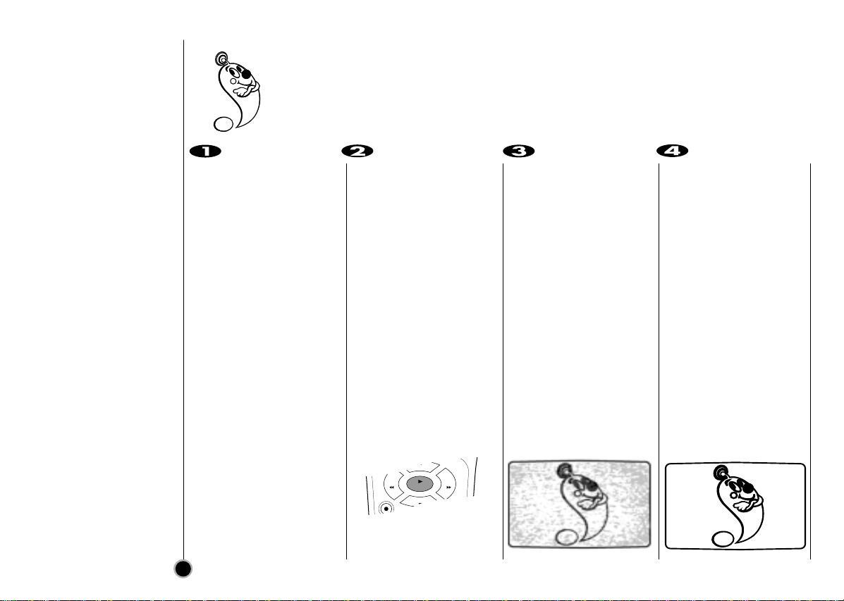
Position your VCR so that no bright light or
sunlight falls directly onto it.
Care should be taken not to expose your
VCR to any unnecessary vibration,
moisture, dust or heat.
During electrical storms it is advisable to unplug both
the aerial cable and mains plug to prevent accidental
damage to your VCR and TV.
Do not operate your VCR if it is damaged.
Your VCR should not be repaired by anyone
except qualified service personnel.
Never remove the top cover of your VCR as this can
expose you to very high voltage and other
hazards. If your VCR does not operate properly,
please check the Troubleshooting Check List on page
34. If your VCR still does not operate properly, unplug
it and call your dealer.
Ensure that your VCR is placed in a position to
allow a free flow of air.
This product is manufactured to comply
with the radio interference requirements
of EEC DIRECTIVE 89/336/EEC,
93/68/EEC and 73/23/EEC.
This appliance is supplied with BS 1363 approved 13
Amp fused mains plug. When replacing the fuse
always use a 5 Amp BS 1362 approved type.
Never use this plug with the fuse cover omitted. To
obtain a replacement fuse cover contact your
supplying dealer or LG Electronics U.K. LTD.
If the mains sockets in your home differ, or are not
suitable for the type of plug supplied then the plug
should be removed and a suitable type fitted.
If the mains plug becomes severed from the mains
lead it must be destroyed. A mains plug with bared
wires is hazardous if engaged in a mains output line
socket.
If a 13 Amp BS 1363 plug is not suitable or any other
type of plug used, then this appliance must be
protected by a 5 Amp fuse.
Should you need to change the plug
The wires in this mains lead are coloured in accordance
with the following codes
BLUE ~ Neutral
BROWN ~ Live
GREEN & YELLOW ~ No connection to be made
As the colours of the wires in the mains lead of this
appliance may not correspond with the coloured markings
identifying the terminals in your plug proceed as follows :
The wire which is coloured BLUE must be connected to the
terminal which is marked with the letter N or coloured
BLACK.
The wire which is coloured BROWN must be connected to
the terminal which is marked with the letter L or coloured
RED.
DO NOT connect the wire which is coloured GREEN &
YELLOW or GREEN.
3
Table of Contents
Welcome to LG
Thank you for buying this LG video cassette recorder Model BC989NI.
Description 2 - 5
Precautions & plug wiring 2
Remote Control Location & function 4
Your VCR’s Controls 5
Setting Up 6 - 16
Connecting to a TV & Satellite 6
Connecting to a Hi-Fi & Camcorder 7
Tuning in a video channel on your TV 8 - 9
How to use the main menu 10
Using your VCR for the very first time 11
Tuning in TV Stations Automatically 12
Tuning in TV Stations Manually 13 - 14
Changing the order of TV Stations 15
Deleting & Selecting TV Stations 16
Basic Operations 17 - 20
Playing a tape 17 - 18
Setting the Colour System 19
Setting the Clock Manually 20
Advanced Operations 21 - 32
Instant Timer Recording (ITR) 21 - 22
VIDEO Plus+ Recording 23 - 24
Timer Recording using On Screen
Display 25- 26
Energy Saving 27
On Screen Display 27
Tape Counter Memory Stop 28
Child Lock 28
Wide Screen Compatibility (16:9) 29
Automatic Memory Power Shut-Off 30
Video Doctor (Self-Diagnosis) 30
Hi-Fi Stereo Sound System 31
ez (easy) operations 32
Helpful Hints 33 - 34
Tape Copying 33
Specifications 33
Troubleshooting Check List 34
Remote Control
Location & Function
Your video recorder (VCR) is designed so that almost all of its features can be controlled from the
REMOTE CONTROL HANDSET. Some features can also be controlled from the FRONT PANEL
of the video recorder. The maximum operating distance that you may control your video recorder
is about 7.5 metres (25 feet). It must also be within an angle of 30 degrees either side of the
REMOTE SENSOR on the front of your video recorder.
To avoid damage from possible battery leakage, remove the batteries if you do not plan to use the remote
control handset for an extended period of time. Do not use batteries of differing age or type. Always discard
batteries safely.
To install batteries:
Your REMOTE CONTROL
HANDSET is powered by
two AA type batteries.
1. To insert them, push
the tab backwards and
lift off the cover of the
handset.
2. Put the two batteries
into the compartment
making sure the + and
– are correctly
positioned.
3. Replace the cover.
POWER
EJECT
CLK/CNT
REC/
ITR
123
456
789
TV/VCR
C.LOCK
ez POWER OFF ez REPEAT
LP AV
0
CM SKIP
CLEAR
OK i
P
/
S
T
I
L
L
S
T
O
P
PLAY
REW FF
SHOWVIEW
VIDEO Plus+
POWER
Switches the VCR on and off
CLEAR
Reset tape counter to zero
OK/CLOCK/TAPE COUNTER
Calls the on screen display.
PAUSE/STILL
Switches to a still picture
REW
Rewinds the tape
Reverse high speed picture play
REC/ITR
Starts instant recording
Numbered buttons
To select channels.
Programme number information on
screen.
TV/VCR
VCR; to monitor, view playback or
view the VCR’s tuner
TV; to watch TV or view another
programme while recording
another programme
VIDEO Plus+
To display the programme menu
for VIDEO Plus+ programming
CHILD LOCK
Switches the Child Lock on and off
ez POWER OFF
(see p. 32)
EJECT
Ejects tape
CURSORS
During playback, tracking control
To control on screen display
information, channel up & down
selection and vertical tremble
during still picture.
i
Displays on screen menu
FF
Winds the tape forwards
Forward high speed picture play
PLAY
To play the tape
STOP
To stop the tape
CM SKIP
To fast forward picture search
through 30 seconds of a
recording
AUDIO/VIDEO MODE
Select input source for recording
LP
To select the recording speed of
the tape
ez REPEAT
(see p. 32)
AA
AA
4
5
Your VCR’s
Controls
Each button on your VCR has the same function as its corresponding button on the
remote control handset.
ENTREE
ANTENNE
SORTIE
ANTENNE
G
R
AUDIO
EURO AV2
DECODER
EURO AV1
AUDIO/
VIDEO
L
D
OUT
SORTIE AERIAL
RF.OUT
VIDEO IN AUDIO IN PROG. REC/ITRP/STILL
(AV3)
L R
Power (ON/OFF)
Video IN
socket
Mains Lead EURO AV1
AUDIO/VIDEO
RF. OUT
(Connect to your TV using
this socket)
EURO AV2
DECODER
Audio IN
sockets Remote
Control Sensor
VCR Display
AERIAL
(Connect the aerial
using this socket)
Channel
Programme
Selectors
Pause/Still
Stop & Tape Eject Cassette
Compartment PLAY
REW
REC/ITR (Instant Record)
FF
AUDIO OUT
sockets
G
R
EURO AV2
DECODER
EURO AV1
AUDIO/
VIDEO
L
D
ENTREE
ANTENNE
SORTIE
ANTENNE
AERIAL
RF.OUT
AUDIO
OUT
SORTIE
6
Connecting
To a TV & Satellite
The guidance given on this page is the most common form of connection. However please check
with your manufacturer’s instruction books for specific information. Make sure all connections are
made with both your VCR and additional appliance unplugged from the mains to avoid
damaging your equipment. Connecting a VCR using a SCART lead is one of the best ways to
achieve optimum sound and picture quality from video-tape playback.
All connections
must be made
with all
appliances
unplugged from
the mains.
SCART Lead (not supplied)
If you use a SCART lead picture quality
will be improved and you will be able to
enjoy stereo when playing tapes (providing
your TV supports stereo sound).
Back view of your VCR
Aerial(not supplied)
The quality of the sound and
picture can be greatly influenced by
the positioning, quality and state of
repair of your external aerial. If you
are unsure about the condition of
your aerial please contact an AIB
registered aerial installation
specialist.
Television
(not supplied)
Satellite (not supplied)
If you connect your VCR
using the supplied
Aerial Connection
Cable (75 Ohms) you will
have to tune in a dedicat-
ed channel on your TV in
order to view video
tapes. Further on in the
book you will be given
guidance on how to tune
in your TV.
Aerial Connection
Cable (75 Ohms)
Do not try and force
the connector into
place, it should plug in
easily.
7
Connecting
To a Hi-Fi &
Camcorder
An audio system can be connected to the
AUDIO OUT sockets on the back of your
VCR.
Please remember to turn the
volume to minimum on your Hi-Fi, then
gradually increase the volume; this will
prevent damaging your speakers and
save you from an extremely noisy shock!
Make sure all connections are made with
both your VCR and camcorder unplugged
from the mains to avoid damaging your
equipment. To make connecting your
camcorder easier we have designed the
Audio IN (Left and Right) and Video IN
sockets on the front panel of your VCR.
VIDEO IN AUDIO IN
SYNC
UBB
LIV
HAL 60 160 400 1K 6.3K
L R
SYNCSYNC
UBBUBB
LIVLIV
HALHAL 60 160160 400 1K 6.3K6.3K
MEMOR
SLEE
AUTO
KHz
MHz
AM
PM
REPEAT 1
1234
5678
9101112
13 14 15 16
AL DIS
RECORD
RE
NR
SYNC
UBB
DISCO
LIV
60 160 400 1K 2.5K 6.3K 16kHz
PM
AM
FLA PO ROC
STEREO MEMORY
SLEEP
AUTO
KHz
MHz
CLASSI
HAL
MUTE
DSP
AB
RANDOM
PROGRA
OVER HI- DUBB
ENTREE
ANTENNE
SORTIE
ANTENNE
G
R
AUDIO
EURO AV2
DECODER
EURO AV1
AUDIO/
VIDEO
L
D
AERIAL
RF.OUT
Hi-Fi
Back view of your
VCR
Audio out sockets & Phono Leads
The phono sockets for connecting your VCR to your Hi-Fi are on the back of the set; L = Left sound output,
R = Right sound output. You normally have to select the AUX function on your Hi-Fi.
Camcorder
Front view of your VCR
Audio Left &
Right Lead
Video Lead
Audio Left &
Right Lead
Make sure that you have
correctly installed your
VCR as described earlier
in this book.
Press POWER to turn on
your VCR.
Turn on your TV.
Insert a pre-recorded
video tape into your VCR
and press PLAY on the
remote control.
Select a TV channel
number on which you
wish to watch videos.
Don’t worry if you don’t have
a video-tape to play at this
stage!
If you switch your VCR on
and continue stages 3~4,
instead of seeing video
playback tune your TV until
you see a bright blue
screen.
Tune this channel until
the video picture is sharp
and the sound is clear.
If you have used a SCART
or AUDIO and VIDEO cables
you will not have to tune your
TV, simply select the AV
channel. The AV channel is
already pre-tuned for opti-
mum video playback on your
TV.
Store this channel on
your TV.
You will need to look at the
TV instruction book if you do
not know how to do this.
8
Tuning in a
Video channel
On your TV
Your TV receives signals from the video recorder (VCR) like another TV station.
You have to select a channel number on your TV and tune it in so that you may watch video
tapes.
If you have used a SCART or AUDIO and VIDEO cables then your TV should already have
a dedicated video channel built into it, usually called AV.
The output frequency of
this video recorder (VCR)
is set at UHF channel 22.
If channel 22 is already
used by another TV
station, or if the picture is
distorted, you can
change the transmitter
channel of your VCR.
Stages 5~8 will show you
how to change the output
frequency of your VCR.
REC/
QSR
P
/
S
T
I
L
L
S
T
O
P
PLAY
REW FF
D
OK
i
9
Only carry out stages
5~8 if you cannot
obtain clear video
playback as described
in stages 1~4.
Select a TV channel
number on which you
wish to watch videos.
Make sure that your VCR
is in standby by pressing
POWER on the remote
control.
(Only the clock will be
displayed.)
Press PROG. Dor E on
the front of your VCR for
more than 4 seconds.
CH22 will appear in the
VCR display.
The following picture will
be displayd on the TV
screen.
Press PROG. Dor E on
the VCR to select
another video channel.
You may select any
channel number between
22 and 68.
Select a TV channel
number on which you
wish to watch video’s.
Tune this channel so that
a bright blue screen
appears.
Store this channel on
your TV.
Press POWER on the
front of your VCR when
you have finished.
Tuning in a
Video channel
On your TV
Make sure that you
have correctly
installed your VCR
and successfully
tuned in a dedicated
video channel on your
TV. If you do not tune in
a dedicated video
channel on your TV you
will be unable to view
and record video tapes!
D
OK
i
i
RF CHANNEL : 22
PR
Turn on your TV set.
Press POWER to turn on
your VCR.
Press i.
The main menu will
appear on the TV screen.
Press F or Gto select
the desired menu.
Press OK and press Dor
Eto select the sub
menu.
Press “i”to remove the
menu.
10
How to
use the main menu
This VCR can easily be programmed by using the menus displayed on screen.
The menus are controlled from the REMOTE CONTROL HANDSET.
LANGUAGE
SELECTION
You can select the
language among English,
Russian, Deutsch,
Français and Polski.
CLK/CNT
CLEAR
OK i
P
/
S
T
I
L
L
LECT
REW AV
CLK/CNT
CLEAR
OK i
P
/
S
T
I
L
L
LECT
REW AV
POWER
EJECT
POWER
EJECT
CLK/CNT
CLEAR
OK i
P
/
S
T
I
L
L
OREC - Timer recording setting (see p. 25 to 26).
OPR - Manual tuning setting (see p. 13 to 14).
OACMS - ACMS (Automatic Channel Memory System) (see p. 12).
OTIME DATE - Date & clock setting (see p. 20).
OSYSTEM - To set the Colour System (see p. 19).
OABC OSD - To change the language setting for OSD (see left).
ODR - To check a problem with your VCR (see p. 30).
OAUDIO - To select the channel for audio output (see p. 31).
OOSD ON/OFF - To switch the display of operational mode of your
VCR ON or OFF (see p. 27).
O16:9/4:3 - To select the aspect ratio of your TV (see p. 29).
OOPR - To improve the playback picture (see p. 18).
ONIC - To activate or deactivate the NICAM digital sound
(see p. 31).
REC REC
OK
i
SYS-
TEM
PR
OPR
AUDIO
Pr-12
ACMS
OSD
ON
OFF
OSD
f
12
TIME
DATE
16:9
4:3
NIC
DR
VCR
AB
C
OSD