LG WM3770H A Series User manual


CONTENTS
1. Specifications .................................................................................................................................. 3
2. Features and Technical Explanation ............................................................................................ 4-6
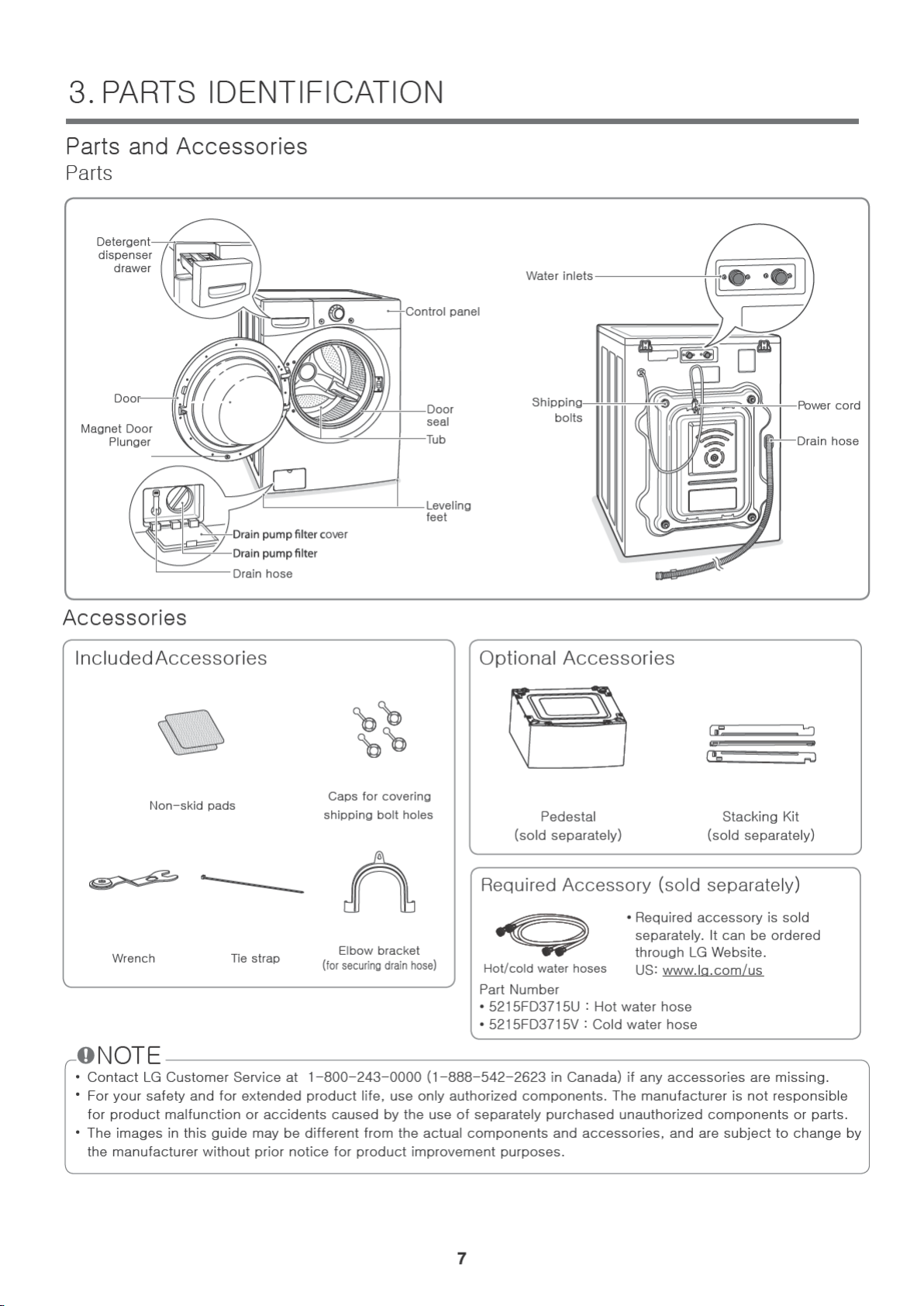
3. Parts Identification ........................................................................................................................... 7
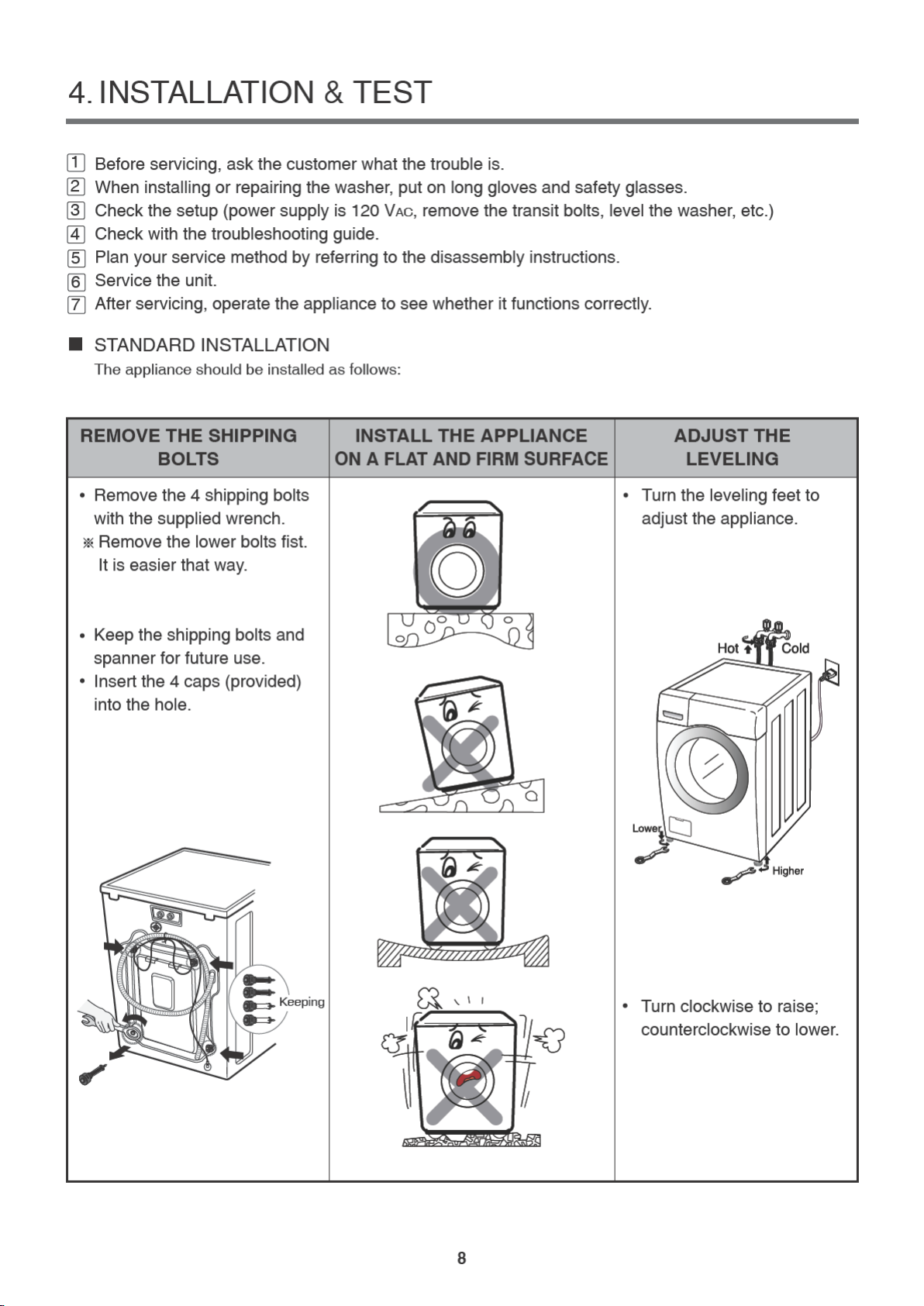
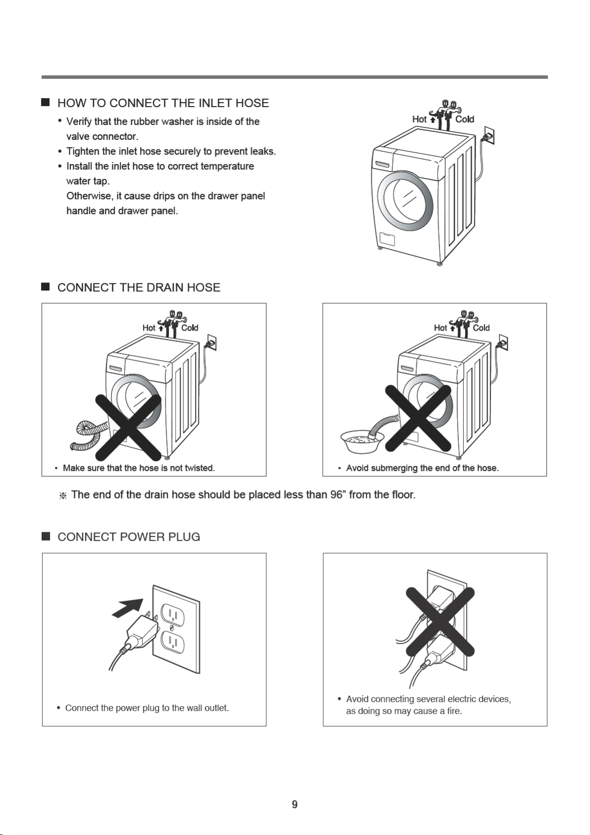
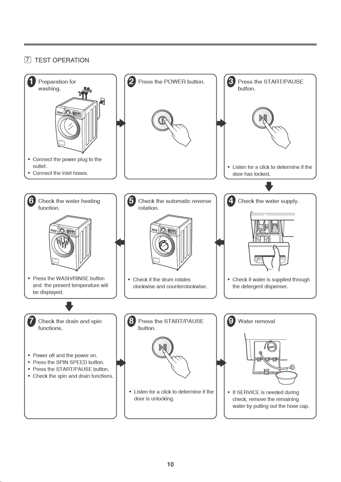
4. Installation and Test ................................................................................................................... 8-10
5. Operation ................................................................................................................................. 11-17
5-1. Control Panel Features ..................................................................................................... 11-13
5-2. Cycle Guide ........................................................................................................................... 14
5-3. Special Functions ................................................................................................................... 15
5-4. Explanation of Each Process ............................................................................................ 16-17
6. Test Mode ...................................................................................................................................... 18
6-1. Safety Caution ....................................................................................................................... 18
6-2. Load Test Mode ..................................................................................................................... 18
6-3. How To Read the Display in Load Test Mode ........................................................................ 18
7. Troubleshooting ............................................................................................................................ 19
7-1. Safety Caution ....................................................................................................................... 19
7-2. Error Mode Summary ....................................................................................................... 19-20
7-3. Troubleshooting With Error ............................................................................................... 21-27
7-5. Before using the Tag On function .......................................................................................... 32
7-4. Troubleshooting Else ........................................................................................................ 28-31
8. Component Testing Information .................................................................................................... 33
8-1. Filter Assembly (Line Filter) ................................................................................................... 33
8-2. Door Look Switch Assembly ............................................................................................. 34-36
8-3. Stator Assembly ......................................................................................................................36
8-4. Pump Motor Assembly ............................................................................................................37
8-5. Inlet Valve Assembly ...............................................................................................................38
8-6. Thermistor Assembly ........................................................................................................ 39-40
9. Disassembly Instructions ........................................................................................................... 41-49
10. Exploded View ......................................................................................................................... 50-52
11. Wiring Diagram ............................................................................................................................. 53
10-1. Cabinet and Control Panel Assembly ................................................................................... 50
10-2. Drum and Tub Assembly ...................................................................................................... 51
10-3. Dispenser Assembly ............................................................................................................. 52
2


5-2. Cycle Guide
The cycle guide below shows the options and recommended fabric types for each cycle.
●
= Available option
CYCLE FABRIC TYPE
BASIC OPTION (
=DEFAULT) ADDITIONAL OPTIONS
Wash
Temp.
Spin
Speed
Soil
Level
Pre
Wash
Extra
Rinse Steam Cold
Wash™
Turbo
Wash™
Fresh
Care
Tub CleanThis cycle is
designed to remove
a mildewy or musty
smell.
Allergiene™
Cotton, underwear,
pillow covers,
bed sheets, baby
wear
Extra High
High★
Medium
Low
No Spin
Sanitary Heavily soiled
underwear, work
clothes, diapers,
etc.
Extra Hot
★Extra High
High★
Medium
Low
No Spin
Heavy
Normal
★
Light
Bright
Whites
™
White Fabrics Hot★
Warm
Cold
Tap Cold
Extra High
High★
Medium
Low
No Spin
Heavy
Normal
★
Light
Bulky/Large Large items such as
blankets and
comforters
Hot
Warm ★
Cold
Tap Cold
Medium ★
Low
No Spin
Heavy
Normal
★
Light
Cotton/
Normal Cotton, linen,
towels, shirts,
sheets, jeans,
mixed loads
Extra Hot
Hot
Warm ★
Cold
Tap Cold
Extra High
High★
Medium
Low
No Spin
Heavy
Normal★
Light
HeavyDuty
Heavy soiled Cotton
FabricsHot
Warm
Cold
Tap Cold
Extra High★
High
Low
No Spin
Heavy★
Normal
Light
Perm.PressDress shirts/pants,
wrinkle-free
clothing, poly/
cotton blend
clothing,
tablecloths
Hot
Warm ★
Cold
Tap Cold
High
Medium ★
Low
Heavy
Normal★
Light
DelicatesDress shirts/
blouses,
nylons, sheer or
lacy garments
Warm
Cold★
Tap Cold
Medium ★
Low
No Spin
Heavy
Normal
★
Light
Towels
Towels Hot
Warm ★
Cold
Tap Cold
Extra High★
High
Medium
Low
No Spin
Heavy
Normal★
Light
Speed WashLightly soiled
clothing
and small loads
Hot★
Warm
Cold
Tap Cold
Extra High★
High
Medium
Low
No Spin
Heavy
Normal
Light★
-Cycle time depends on type and amount of load and detergent,water pressure and chosen additional
options.
-If the Turbo Wash™ option is on, you cannot select “No Spin” as your Spin Speed.
(If the Turbo Wash™ option is off, you can select “No Spin” as your Spin Speed.)


5-4. Explanation of each process
No. noitanalpxEssecorP
1. Stay •Electrical power is supplied.
•Washer is ready to work and the micom is in the active mode.
2. Water
supply
•After loading laundry and selecting a course and a cycle, water is
supplied and drum rotates.
•When a user selects Pre-wash course, water is supplied through pre
wash valve.
3.
Soaking
and washing
laundry
•To get laundry wet, drum rotates clockwise and counterclockwise.
•If water amount is insufficient at this time, the Inlet valve will supply
water again.
4.
Heating and
washing
•The heater heats the water in drum to the selected water temperature
and drum rotates for washing.
5.
6.
Washing
and heating
/ washing
•When the water temperature reaches to the selected temperature,
the heating stops and only the drum rotates.
•If water temperature becomes lower than selected because of
re-supplied water, the heating starts again.
7. Washing •Fuzzy logic decides washing time according to the laundry load, water
temperature, and other factors.
8. Drainage •A pump motor drains the water from the drum.
•After sensing drained water amount by water level frequency, spin starts.
•When a heating course is selected, stay cooling process is performed to
decrease the water temperature gradually to prevent laundry from being
damaged and for safety reasons.
9. Untangling
(Sensing
eccent-
ricity)
•It balances laundry load and senses the eccentricity of the load, to only
allow spinning without vibration.
•If the eccentricity is worse than the allowed level, it repeats the
disentangling process. When the repeated time is more than allowed
level, it displays UE.
•If the eccentricity is good, the intermittent spin starts.
•During this process, the drain pump works for drainage intermittently.
16

No. noitanalpxEssecorP
10 Intermittent
spin
•To reach the correct set speed, the motor rotates clockwise and
counterclockwise directions after spin process starts.
•If the water level frequency is lower than 23.0 kHz,
a washer senses suds and starts suds removal process.
11 Rinse
spin
•In this process, the remaining water during washing process is
extracted and the selected speed is kept.
•Removing suds process is in active mode at this cycle.
12 Remaining
spin
•After spin finishes, the drum rotates by remaining spin power until it
stops. Motor power is off.
•This process is overlapped with next process.
13 Rinse water
supply
•Water supply for rinse process.
14 Rinse •Rinsing process.
15 Last
drainage
•After spin finishes and power is not supplied to motor, the drum
rotates by remaining spin power.
•If rinse hold is selected, the drainage is not proceeded after rinse
finishes.
16 Disentangling •The same as item 9.
17
Intermittent spin
•The same as item 10.
18
19
20
21
22
Main spin1 •The same as item 11.
Main spin2•At the end of a main spin, the spin speed will reach the selected rpm.
Remaining spin•The same withitem 12.
Disentangling•After spin finishes, disentangling starts to remove unbalanced
laundry.
End •After ‘end’ signal is displayed, it stays for 8 seconds and power is
automatically turned off. (Auto type door switch)
•After door switch is off, end signal is displayed in the case of
manual type and it takes around 2 minute to turn off door switch.
17


Table of contents
Other LG Washer manuals