Disassembly and Reassembly
A. Removing the PC Boards
1. Power the LI-6400 off, and disconnect all cables and batteries
2. Assemble the tools shown below; be sure to use the disposable grounding wrist strap (not pictured) before
opening the LI-6400 console case or beginning the installation procedure.
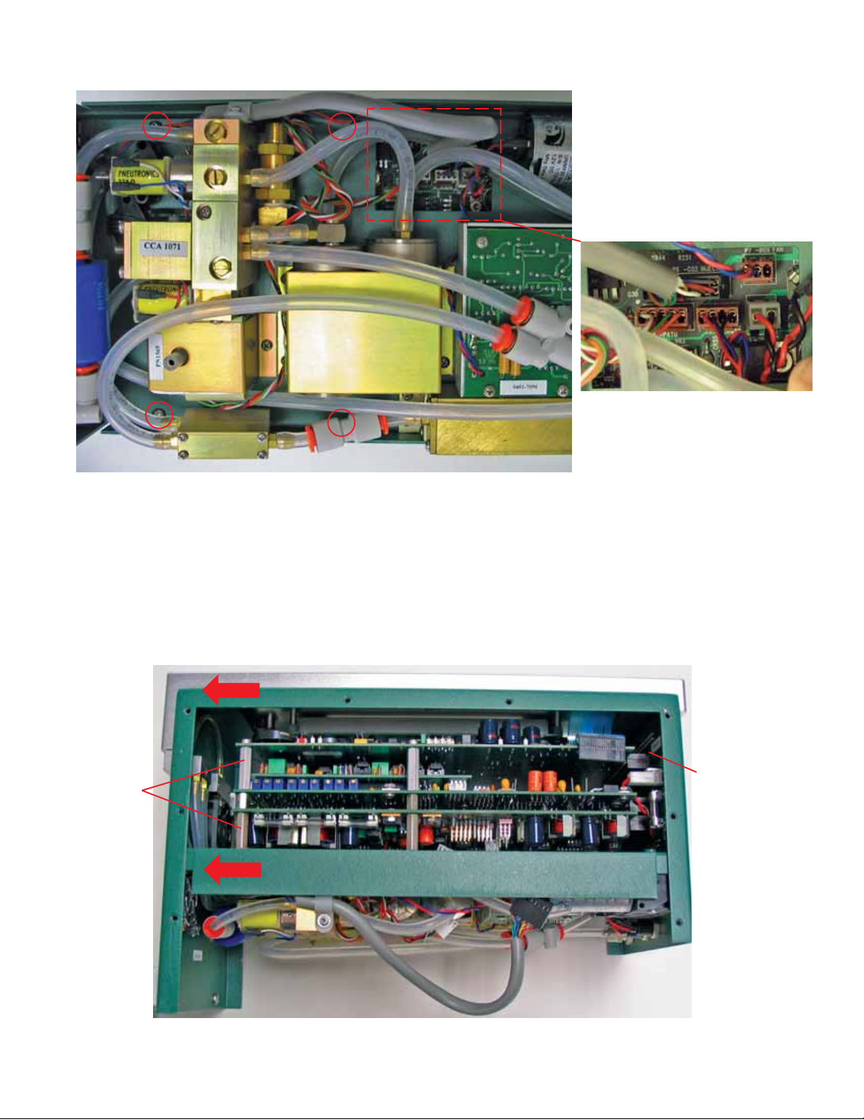
3. Remove the console bottom shell
There are 8 screws on the front and rear panels that must be removed. Remove the batteries from the shell; the
old shell will not be re-used, and can be discarded. Make sure to loosen the 4 spring-loaded screws on the
bottom of the shell; remove the plate that has the rubber feet attached and install the plate on the new shell.
4. Unplug the display and keyboard connectors
Unplug the keyboard connector by carefully lifting it up from the pins on which it sits (Figure 6).Then, unplug
the display connector on the other side of the console (B). Finally, if there is one, unplug the back light connec-
tor (C).
Phillips head screw-
driver (#1 or #2)
11/32" nut driver
11/32" open end wrench
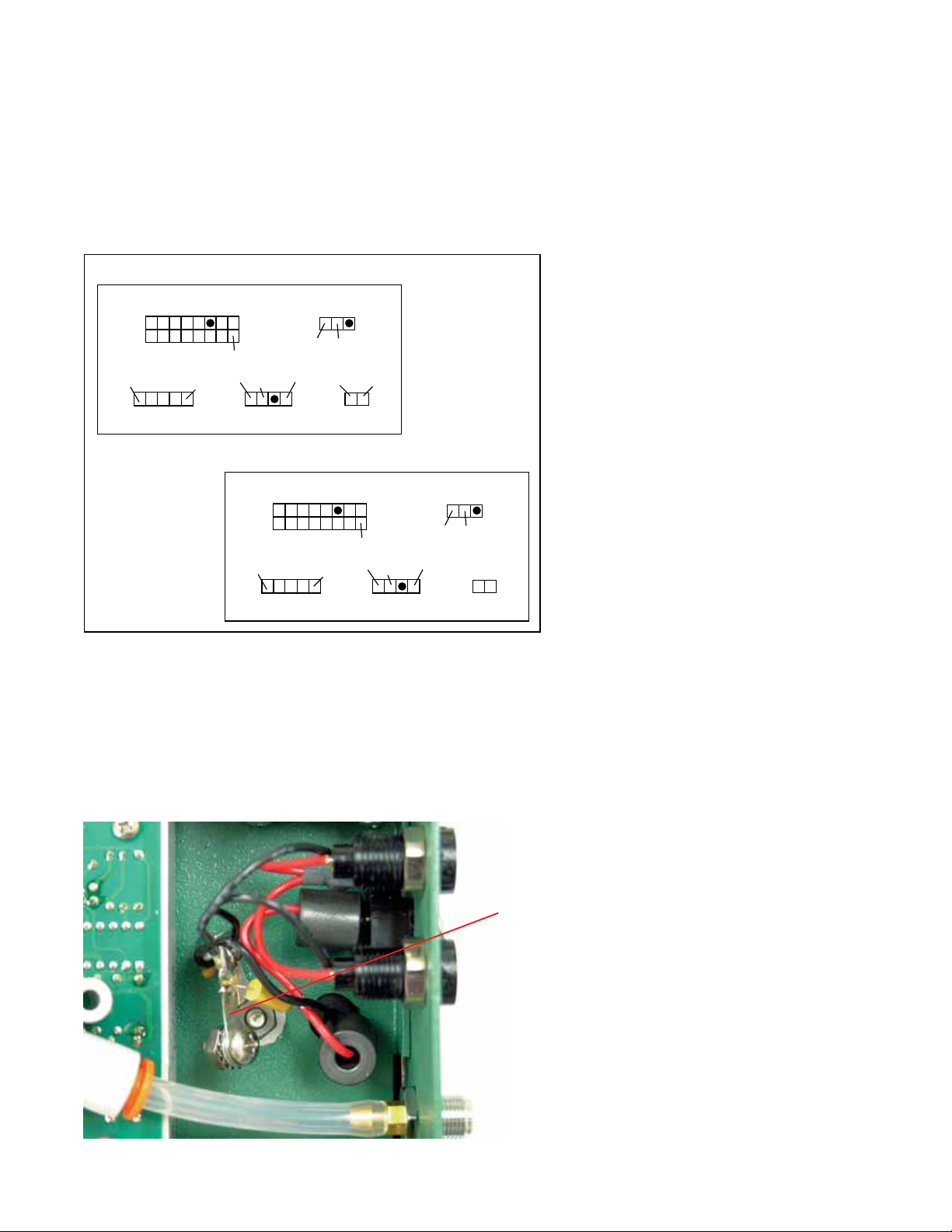
Diode circuit
Needle nose pliers
Kep nuts, star
washer, and
screw
NOTE: The 11/32” nut driver and open
end wrench are required only when
installing the diode circuit. Your
instrument may have the diode circuit
installed already; if so,you can skip the
instructions on page 7 (Installing the
Diode Assembly). See page 7 for
location of diode assembly.
4
Figure 4. Unplug the keyboard connector
by lifting straight up; be careful not to bend
the ribbon cable attached to the connector.
Keyboard connector
Backlight connector
Figure 5. Turn the console around and unplug
the display and backlight connectors (if
present).
Display connector