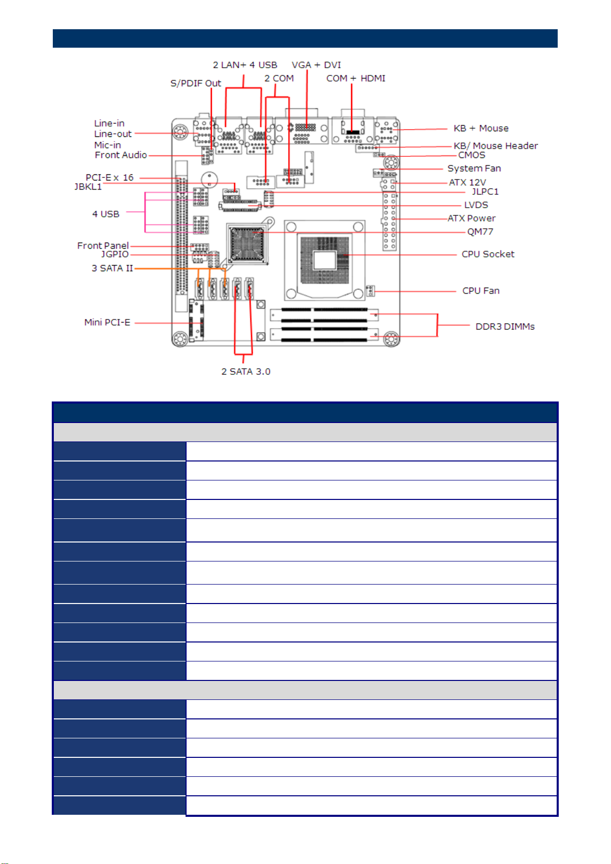
Liantec ITX-QM77 User manual

ITX-QM77
Mini-ITX Intel QM77 Ivy Bridge Mobile Motherboard
Supports Intel 3rd Generation Core-i7 / i5 / i3 Processor
Quick Installation Guide
Packing List
Before you begin installing your single board, please make sure that the
following parts have been shipped.
1 x ITX-QM77 Mini-ITX motherboard
1 x CPC-1500C 1U copper-based CPU cooler
2 x SATA cable with lockable clips
2 x RS-232 COM port DB9 male cable with brackets
1 x DVD disc with OS drivers and user’s manual
1 x Quick Installation Guide
Disclaimer and Notice
The manufacturer reserves the right to make changes,
without notice, to any product, including circuits and/or
software described or contained in this manual in order to
improve design and/or performance. The manufacturer
assumes no responsibility or liability for the use of the
described product(s), conveys no license or title under
any patent, copyright, or masks work rights to these
products, and makes no representations or warranties
that these products are free from patent, copyright, or
mask work right infringement, unless otherwise specified.
For the detail product information, please refer to user’s
manual.
Safety Declaration
This device complies with the requirements in Part 15 of
the FCC rules. Operation is subject to the following two
conditions:
1. This device may not cause harmful interference.
2. This device must accept any interference received,
including interference that may cause undesired
operation.
2012-09-07

Product Overview
Specifications
System
CPU
Intel Core i7/ i5/ i3 Pentium®/ Celeron® Mobile CPU
BIOS
AMI 64Mb SPI ROM
System Chipset
Intel QM77
I/O Chipset
Nuvoton NCT6776F
Memory
Two 204-pin SODIMM support up to 16GB dual channel DDR3 1600/ 1333
SDRAM, Non-ECC
Watchdog Timer
Reset: 1 to 255 sec/min per step
H/W Status Monitor
Monitoring temperature, voltage and cooling fan status. Auto throttling control
when CPU overheats.
Expansion Slots
1 PCI-E x 16 Gen. 3, 1 Mini PCI-E, 1 CFast
Power State
S1, S3, S4, S5
TPM
TPM 1.2 by Infineon SLB9635 (optional)
Wake up / Boot on LAN
LAN (WOL,PXE)
Smart Fan Control
Yes
Display
Chipset
Intel GMA HD 4000 /2500 (22nm) , 3000/2000(32nm)
Display Memory
Shared Memory, up to 256MB
Dual Display
VGA + LVDS, VGA + HDMI, VGA + DVI, LVDS + HDMI, LVDS + DVI, HDMI + DVI
VGA
Onboard, supports max resolution 2048 x 1536 (@75Hz)
LVDS
Onboard 24-bit LVDS, supports max resolution 1920 x 1200
HDMI
Onboard HDMI 1.3, supports max resolution 1920 x 1200

DVI
Onboard DVI-D, supports max resolution 1920x1200
LVDS Backlight
Yes
Audio
Audio Codec
Realtek ALC892, 5.1 Channel HD Audio
Audio Interface
Line-in, line-out, Mic-in, S/PDIF Out, Front Audio Header
Ethernet
LAN1
Intel 82579LM GbE LAN supports iAMT 8.0
LAN2
Intel 82583V GbE LAN
Jumpers
Label
Function
Note
JCMOS1
Clear CMOS
Normal *
Clear CMOS
JCOMPWR2
JCOMPWR3
COM2 COM3
RI/+5V/+12V Select
RI
+5V
+12V
JLVDS_BKL1
BL POWER SELECT
5V
3.3V
JPSON
AT MODE
ATX MODE
Connectors
Label
Function
Note
CPU_FAN
CPU Fan
Connector
SYS_FAN1
System Fan
Connector
Connectors
Label
Function
Note
COM2
COM3
Serial Port
Connector
F_PANEL1
Intel Front
Panel
connector
1.GND
2.CPUFAN1_VCC(PWM)
3.CPUFAN1_IO
1.GND
2.SYSFAN1_VCC(PWM)
3.SYSFAN1_IO
1.ATSEL IN
2.PWRBT
3.ATXSEL
IN
1.+5V
2. BRIGHT 1
3. 3.3V
1.DCD 6.DSR
2.RXD 7.RTS
3.TXD 8.CTS
4.DTR 9.RI/PWR
5.GND
1.HDDLED+ 2.POWERLED+
3.HDDLED- 4.POWERLED-
5.GND 6.PWSWITCH
7.RESET 8.GND
9.NC

JLVDS
24-bit LVDS
Connector
JBKL
LCD Inverter
Connector
JLPC1
LPC
Connector
FPAUD1
Audio Mic.-In
& Line-Out
Connector
JGPIO1
GPIO
Connector
SPDIF_OUT
SPDIF OUT
Connector
USB56
USB78
USB910
USB1112
USB 2.0
Connector
ATX12V1
1.VDD(+3.3V) 11.LVDS_A1- 21.LVDS_B1+ 31.GND
2.VDD(+5V) 12.LVDS_A0- 22.LVDS_B0+ 32.GND
3.VDD(+3.3V) 13.GND 23.LVDS_B1- 33.LVDS_B_CK+
4.VDD(+5V) 14.GND 24.LVDS_B0- 34.LVDS_A_CK+
5.I2C_CLK 15.LVDS_A3+ 25.GND 35.LVDS_B_CK-
6.I2C_DATA 16.LVDS_A2+ 26.GND 36.LVDS_A_CK-
7.GND 17.LVDS_A3- 27.LVDS_B3+ 37.GND
8.GND 18.LVDS_A2- 28.LVDS_B2+ 38.GND
9.LVDS_A1+ 19.GND 29.LVDS_B3- 39.VDD(+12V)
10.LVDS_A0+ 20.GND 30.LVDS_B2- 40.VDD(+12V
9.NC
8.GND 7.GND
6.USB+ 5.USB+
4.USB- 3.USB
2.USB+5V 1.USB+5V
1.+5V
2.
3.SPDIF OUT
4.GND
1.SIO_GPIO0 6.SIO_GPIO6 11.GND
2.SIO_GPIO4 7.SIO_GPIO3 12.VCC GPIO
3.SIO_GPIO1 8.SIO_GPIO7
4.SIO_GPIO5 9.SMB_CLK_RESUME
5.SIO_GPIO2 10.SMB_DAT_RESUME
10.LINE_JD 9.LIN2_L
8.NC 7.FIO_SENSE
6.MIC2_JD 5.LIN2_R
4.PRESENSE 3.MIC2_R
2.GND 1.MIC2_L
1.NC 7.LPC_FRAME#
2.+3.3 8.LPC_AD0
3.LPC_AD3 9.
4.PRST_SIO# 10.GND
5.LPC_AD1 11.CLK33M_LPC
6.LPC_AD2 12.GND
1.+12V
2.GND
3.ENBKL
4.VR
5.+5V
KB/Mouse PIN Header
1.KB b CLK
2.KB b DAT
3.MS b DAT
4.GND
5.VCC_KBMS
6.MS_b_CLK
Table of contents