manuals.online logo
Brands
  1. Home
  2. •
  3. Brands
  4. •
  5. Liberty Pumps
  6. •
  7. Water Pump
  8. •
  9. Liberty Pumps ProVore PDC-115 User manual

Liberty Pumps ProVore PDC-115 User manual

Installation Manual
7000 Apple Tree Avenue
Bergen, NY 14416
ph: 800-543-2550
fax: 585-494-1839
www.LibertyPumps.com
Copyright © Liberty Pumps, Inc. 2019
All rights reserved.
8338000E
# NITW.E134903
# NITW7.E134903
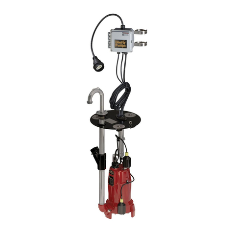
ProVore® Duplex Control
Designed for use with Liberty Pumps ProVore®1 hp residential grinder pumps
Indoor Models
PDC-115
115 Volt
PDC-230
230 Volt
Outdoor Models
PDCW-115
115 Volt
PDCW-230
230 Volt
Contents
Safety Precautions . . . . . . . . . . . . . . . . . . . . . . . . . . . . . . . . . . . . . . . . . . . . . . 2 | EN
Control Panel Design . . . . . . . . . . . . . . . . . . . . . . . . . . . . . . . . . . . . . . . . . . . . 3 | EN
Primary Power . . . . . . . . . . . . . . . . . . . . . . . . . . . . . . . . . . . . . . . . . . . . . . . . . 3 | EN
Battery Backup Power . . . . . . . . . . . . . . . . . . . . . . . . . . . . . . . . . . . . . . . . . . . 5 | EN
Warranty . . . . . . . . . . . . . . . . . . . . . . . . . . . . . . . . . . . . . . . . . . . . . . . . . . . . . . 6 | EN
2 | EN Copyright © Liberty Pumps, Inc. 2019
All rights reserved. 8338000E
Safety Guidelines
Safety Precautions
Accidental contact with electrically live parts, items, fluid, or
water can cause serious injury or death.
Always disconnect pump(s) from power source(s) before
handling or making any adjustments to either the pump(s),
the pump system, or the control panel.
All installation and maintenance of pumps, controls,
protection devices, and general wiring shall be done by
qualified personnel.
All electrical and safety practices shall be in accordance with
the National Electrical Code®, the Occupational Safety and
Health Administration, or applicable local codes and
ordinances.
Pump shall be properly grounded using its supplied
grounding conductor. Do not bypass grounding wires or
remove ground prong from attachment plugs. Failure to
properly ground the pump system can cause all metal
portions of the pump and its surroundings to become
energized.
The electrical power supply shall be located within the length
limitations of the pump power cord, and for below grade
installations it shall be at least 4 ft (1.22 m) above floor level.
Do not use this product in applications where human contact
with the pumped fluid is common (such as swimming pools,
fountains, marine areas, etc.).
Do not use an extension cord to power the product.
Extension cords can overload both the product and extension
cord supply wires. Overloaded wires will get very hot and can
catch on fire.
This product requires a separate, properly fused and
grounded branch circuit, sized for the voltage and amperage
requirements of the pump, as noted on the nameplate.
Overloaded branch circuit wires will get very hot and can
catch on fire. When used, electrical outlets shall be simplex of
the appropriate rating.
Do not modify the pump/pump system in any way.
Modifications may affect seals, change the electrical loading
of the pump, or damage the pump and its components.
All pump/pump system installations shall be in compliance
with all applicable Federal, State, and Local codes and
ordinances.
Do not use this product with flammable, explosive, or
corrosive fluids. Do not use in a flammable and/or explosive
atmosphere as serious injury or death could result.
This safety alert symbol is used in the manual and on the pump to alert of potential risk for serious injury
or death.
This safety alert symbol identifies risk of electric shock. It is accompanied with an instruction intended to
minimize potential risk of electric shock.
This safety alert symbol identifies risk of fire. It is accompanied with an instruction intended to minimize
potential risk of fire.
This safety alert symbol identifies risk of serious injury or death. It is accompanied with an instruction
intended to minimize potential risk of injury or death.
Warns of hazards which, if not avoided, will result in serious injury or death.
Warns of hazards which, if not avoided, could result in serious injury or death.
Warns of hazards which, if not avoided, could result in minor or moderate injury.
Read every supplied manual before using pump system. Follow all the safety instructions in
manual(s) and on the pump. Failure to do so could result in serious injury or death.
Installer: manual must remain with owner or system operator/maintainer.
Record information from pump nameplate:
Keep this manual handy for future reference. Model #:
For replacement manual, visit
LibertyPumps.com, or contact Liberty Pumps at
800-543-2550.
Serial #:
Manufacture Date:
Retain dated sales receipt for warranty. Install Date:
RISK OF ELECTRIC SHOCK RISK OF FIRE
RISK OF SERIOUS INJURY OR DEATH
8338000E Copyright © Liberty Pumps, Inc. 2019
All rights reserved. 3 | EN
Control Panel Design
The ProVore®Duplex Control system (PDC-Series) monitors the
operation of two ProVore grinder pumps. The control system
comes in two parts: the controller with user interface and the float
switches mounted inside the basin. The P680 system includes two
ProVore pumps and two float switches.
The control panel monitors the liquid level in the basin and
alternates the two grinder pumps each cycle such that both
pumps receive equal wear. In the event one pump should fail, the
system automatically switches to the other pump.
LEDs and pushbuttons allow the operator to monitor and control
the system. Controllers require a dedicated circuit of proper
amperage. The PDC(W)-115 requires 115V/20A dedicated service,
while the PDC(W)-230 requires 230V/15A dedicated service.
The controller normally operates on primary power (115 VAC or
230 VAC), but if that power fails, an internal 9-volt battery allows
the controller to monitor liquid level and activate the alarm as
required.
On backup power (9-volt battery), the controller cannot run the
pumps. Pumps will only operate when primary power is supplied
to the control panel. The operator can test the alarm circuits,
change the horn status. Since pumps do not operate while the
controller is on backup power, the manual pump run feature will
not be functional.
Indoor PDC Models
The two float switches are connected such that only three cords
exit the cover. All three cords (two pump power cords and one
control cord) must be plugged into the controller box.
Outdoor PDCW Models
Outdoor models require power and control cord hardwiring. The
inner panel must be removed to provide access to the terminal
blocks inside the panel. The pump and switch plugs must be cut
off and wires stripped. Feed the cords, along with the incoming
power, through the liquid-tight strain relief bushings and wire into
the terminal block mounted in the PDC panel. A wiring schematic
is provided next to the terminal block. The panel has a secondary
terminal block for auxiliary contacts as required.
Primary Power
General Operation (115 VAC and 230 VAC)
The PDC panel controls the operation of two ProVore grinder
pumps in a pump-down application. Two floats are mounted to
the quick tree: a primary pump control float switch and an alarm
float switch. On the controller are indicators that show operating
conditions: High Water Alarm status, Pump Run status, Horn
status (indoor model), and incoming Power status. Operator
pushbutton controls are available to manually run the pumps, test
the alarm, enable or disable the horn (indoor model), as well as
reset the system. Both pumps are individually protected with a
manual resettable fuse to isolate a failed pump.
When the incoming water activates the primary pump float switch,
the controller will energize one of the pumps. Normally the water
level in the sump will recede as the pump operates and the pump
will turn OFF when the primary pump float switch drops to the
OFF position. Upon the next pumping cycle, the controller will
activate the next pump in sequence from the one that ran
previously, providing a pumping redundancy for the system. The
controller will continue to alternate pumps on each cycle.
Power cord
PDC-115: 115V 20A
PDC-230: 230V 15A
Switch disconnect
User interface buttons
LED indicators
9-Volt battery
backup
Receptacles
pump 1 and 2
Resettable breakers
20 Amp (115V)
15 Amp (230V)
Lockable latch
Alarm silence switch
RED alarm beacon
Alarm horn
9-Volt battery
backup
Liquid-tight connectors
Resettable breakers
20 Amp (115V)
15 Amp (230V)
User interface buttons
LED indicators
inner panel must be
removed in order to
hardwire the system
terminal block:
• incoming power
• pump 1
• pump 2
• float switch
cord entry liquid-
tight strain relief
ground lugs
auxiliary contacts
4 | EN Copyright © Liberty Pumps, Inc. 2019
All rights reserved. 8338000E
Controller Indicators
The horn, LED indicators, and Alarm Beacon (outdoor models) are
used to show various conditions of the controller. Each indicator is
described in Table 1. *A flashing LED indicates a component has
failed or is disabled.
Figure 1. Indoor and Outdoor Panels
Operator Controls
The operator has access to controls to silence the horn alarm, test
the alarm circuits, manually run the pumps, and reset the panel.
Each pump is protected by a manual resettable fuse. Fuses are
located on the side panel for the indoor models and inside the
cover for the outdoor models.
Table 1. Indicators
Indicator State Description
High Water
Alarm LED
OFF No alarm condition.
ON Steady An alarm condition is present.
Flashing*
Alarm float switch is not working
properly, may be mechanically
stuck closed or tangled in a closed
condition.
Horn
Disabled
LED
(indoor
models)
Flashing*
Horn operation is Disabled. The
horn will not sound in an alarm
condition.
OFF
Horn operation is Enabled. The
horn will sound in an alarm
condition.
Alarm
Beacon
(outdoor
models)
ON Steady An alarm condition is present.
Pump 1 Run
LED
OFF Pump is not being called to run.
ON Steady Pump is being called to run.
Flashing*
Pump failed to operate; fuse
tripped, jammed impeller,
unplugged, short circuit, etc.
Pump 2 Run
LED
OFF Pump is not being called to run.
ON Steady Pump is being called to run.
Flashing*
Pump failed to operate; fuse
tripped, jammed impeller,
unplugged, short circuit, etc.
Pump 1 Run
and Pump 2
Run LED
Flashing*
Primary float switch is not working
properly, may be mechanically
stuck closed or tangled in an open
condition.
Power LED
OFF
No AC power, main breaker has
tripped, or power outage and
battery is dead.
ON Steady Primary power to the panel is ON.
Flashing*
Primary power to the panel is OFF;
the panel is on alarm backup
power. Pumps will NOT run.
Alarm Horn
OFF
No alarm condition and the alarm
backup battery is in good
condition.
ON An alarm condition is present.
Chirping
The voltage of the alarm backup
battery is low and the battery
should be replaced.
Table 2. Operator Controls
Control
Pushbutton
Existing
Condition Action When Pressed
Alarm Test —
Alarm indicator, auxiliary relay,
and horn (if enabled) turn ON.
These actions remain until the
button is released.
Horn Silence
(indoor
models)
Horn
Disabled
LED flashing
Horn Disabled indicator will turn
OFF and the horn be Enabled.
Horn
Disabled
LED OFF
Horn Disabled indicator will start
flashing and the horn will be
Disabled for 12 hours. After 12
hours, the indicator will
automatically turn OFF and the
horn will then be Enabled.
Pump Run
A pump is
running
The pump that is running will be
turned OFF; the next pump in
sequence will be turned ON. That
pump will remain ON as long as
the pushbutton is held. When the
pushbutton is released, that
pump will turn OFF if the
condition calling for a pump to
run is no longer present.
Neither
pump is
running
The next pump in sequence will
be turned ON and will remain
ON until the button is released.
Table 1. Indicators (continued)
Indicator State Description
8338000E Copyright © Liberty Pumps, Inc. 2019
All rights reserved. 5 | EN
Alarm Operation
In the event water fills the tank faster than it can be pumped out,
or if a pump fails to operate, the level can reach an alarm point by
activating the alarm float switch. If the alarm float remains closed
(up position) for 6 hours but the primary float switch is open
(down position), the High Water Alarm LED will flash and the
pump is turned off. This feature prevents the pump from running
indefinitely.
Active Alarm Condition
The following occurs when an alarm condition activates:
1. The pump that is (or should be) running is turned OFF and
the next pump in sequence is turned ON.
2. If the alarm float remains closed (float switch in up position)
for 4 sec., the High Water Alarm LED will illuminate steady.
3. The auxiliary relay will activate, closing its normally open
contacts and opening its normally closed contacts.
4. If the horn is enabled (i.e., Horn Disabled LED not flashing),
the horn will sound.
Post Alarm Condition
An alarm condition will remain active until the liquid level drops
below the pump float switch. When this occurs, the following will
take place:
1. The running pump will turn OFF.
2. The High Water Alarm LED will turn OFF.
3. The auxiliary relay will deactivate.
4. The horn (if ON) will turn OFF.
Pumping Alarm Condition
The controller monitors a “pumping alarm condition” where a
pump is called to run and the liquid level continues to rise and
goes above the alarm float switch. If a pumping alarm condition
occurs three or more of the last five times a pump is called to run,
the pump LED will flash indicating system components should be
checked. Any of the following conditions could cause a pumping
alarm condition:
1. A pump fails to operate.
2. The alarm float switch stays (mechanically stuck) in the closed
(ON or up) position.
3. There is a problem (blocked or leak) in the outflow plumbing.
4. The water inflow rate is greater than the pump out rate.
5. The primary float switch stays (mechanically stuck) in the
open (OFF or down) position.
A flashing LED indicates a component has failed and service is
required. To assist the service technician, the controller will
indicate which component has failed. Refer to Table 1.
Battery Backup Power
General Operation
On battery backup power, the controller is limited to alarm and
horn status indicators. The controller cannot run the pumps.
Pumps will only operate when primary power (115 VAC or
230 VAC) is supplied to the control panel.
The alarm float switch mounted in the tank monitors the liquid
level to indicate when an alarm level is reached. The pump float
switch is not used when the panel is on battery backup power
since pumps cannot operate.
Panel indicators show operating conditions of High Water Alarm
and Horn status. Operator pushbutton controls are available to
disable the alarm horn and reset the system.
When the liquid level drops below the alarm float, the float switch
will open, removing the alarm condition; likewise when the liquid
level rises above the alarm float, the float switch will close and an
alarm condition will be indicated.
Alarm Operation
As water fills the tank and the liquid level rises above the alarm
float, the float switch will be ON and an alarm condition is
activated. The following occurs when an alarm condition activates:
1. The High Water Alarm LED will flash.
2. The auxiliary relay will activate once for one minute, closing
its normally open contacts and opening its normally closed
contacts, then will deactivate.
3. If the horn is enabled (i.e., Horn Disabled LED not flashing),
the horn will sound.
Test - Reset
High Water
Alarm,
Pump 1 Run
and/or
Pump 2 Run
LEDs are
flashing
When pushbutton is depressed,
the system will reset and LEDs
will stop flashing.
Alarm Silence
Switch on
unit exterior
(outdoor
models)
Alarm is
sounding Alarm is silenced.
Fuse Blown fuse. Reset fuse.
Table 2. Operator Controls (continued)
Control
Pushbutton
Existing
Condition Action When Pressed
6 | EN Copyright © Liberty Pumps, Inc. 2019
All rights reserved. 8338000E
Panel Indicators
The horn and LEDs are used to show various conditions in the
controller. Each indicator is described in Table 3. Note that on
backup power, no LEDs will be illuminated steady.
Operator Controls
The operator has access to controls to silence the horn alarm, test
the alarm circuits, and reset the panel.
Warranty
Liberty Pumps Wholesale Products Limited
Warranty
Liberty Pumps, Inc. warrants that Liberty Pumps wholesale
products are free from all factory defects in material and
workmanship for a period of three (3) years from the date of
purchase (excluding batteries). The date of purchase shall be
determined by a dated sales receipt noting the model and serial
number of the pump. The dated sales receipt must accompany the
returned pump if the date of return is more than three years from
the date of manufacture noted on the pump nameplate.
The manufacturer's sole obligation under this Warranty shall be
limited to the repair or replacement of any parts found by the
manufacturer to be defective, provided the part or assembly is
returned freight prepaid to the manufacturer or its authorized
service center, and provided that none of the following
warranty-voiding characteristics are evident:
The manufacturer shall not be liable under this Warranty if the
product has not been properly installed, operated, or maintained
per manufacturer instructions; if it has been disassembled,
modified, abused, or tampered with; if the electrical cord has been
cut, damaged, or spliced; if the pump discharge has been reduced
in size; if the pump has been used in water temperatures above
the advertised rating; if the pump has been used in water
containing sand, lime, cement, gravel, or other abrasives; if the
product has been used to pump chemicals, grease, or
hydrocarbons; if a non-submersible motor has been subjected to
moisture; or if the label bearing the model and serial number has
been removed.
Liberty Pumps, Inc. shall not be liable for any loss, damage, or
expenses resulting from installation or use of its products, or for
indirect, incidental, and consequential damages, including costs of
removal, reinstallation or transportation.
There is no other express warranty. All implied warranties,
including those of merchantability and fitness for a particular
purpose, are limited to three years from the date of purchase.
This Warranty contains the exclusive remedy of the purchaser,
and, where permitted, liability for consequential or incidental
damages under any and all warranties are excluded.
Table 3. Backup Power Indications
Indicator State Description
High Water
Alarm LED
OFF There is no alarm condition.
Flashing An alarm condition is active.
Horn
Disabled LED
(indoor
models)
OFF
Horn operation is Enabled. The
horn will beep in an alarm
condition.
Flashing Horn operation is Disabled.
Pump 1 Run
LED OFF The Pump 1 indicator will always be
OFF when on alarm backup power.
Pump 2 Run
LED OFF The Pump 2 indicator will always be
OFF when on alarm backup power.
Power LED
OFF Power is off to the panel and the
backup alarm battery is dead.
Flashing
Primary power to the panel is Off;
the panel is on alarm backup
power. Pumps will not run.
Alarm Horn OFF No alarm condition is present.
Beeping An alarm condition is present.
Table 4. Backup Power Operator Controls
Control
Pushbutton
Existing
Condition Action When Pressed
Alarm Test —
Horn, alarm indicator, and auxiliary
relay will turn on. They will remain
in that state until the button is
released.
Horn Silence
(indoor
models)
Horn
Disabled
indicator
is flashing
Horn Disabled indicator will stop
flashing and the horn will be
enabled.
Horn
Disabled
indicator
is OFF
Horn Disabled LED will start
flashing and the horn will be
disabled for 12 hours. After 12
hours, the indicator will turn off
automatically and the horn will
then be enabled.
Pump Run — Not available on battery power.
Test - Reset —Resets the system; all LEDs will stop
flashing.
Alarm Silence
Switch on
unit exterior
(outdoor
models)
Alarm is
sounding Alarm is silenced.
©2019 SJE, Inc. All Rights Reserved.
SJE RHOMBUS is a trademark of SJE, INC.
PN 1038601B • Rev 11/19

This manual suits for next models

3

Other Liberty Pumps Water Pump manuals

Liberty Pumps SumpJet SJ10 User manual

Liberty Pumps

Liberty Pumps SumpJet SJ10 User manual

Liberty Pumps Pro370 Series User manual

Liberty Pumps

Liberty Pumps Pro370 Series User manual

Liberty Pumps LSG202M User manual

Liberty Pumps

Liberty Pumps LSG202M User manual

Liberty Pumps Pro680 Series User manual

Liberty Pumps

Liberty Pumps Pro680 Series User manual

Liberty Pumps Omnivore RE Series User manual

Liberty Pumps

Liberty Pumps Omnivore RE Series User manual

Liberty Pumps Omnivore LSG Series User manual

Liberty Pumps

Liberty Pumps Omnivore LSG Series User manual

Liberty Pumps 404 User manual

Liberty Pumps

Liberty Pumps 404 User manual

Liberty Pumps 2LE Series User manual

Liberty Pumps

Liberty Pumps 2LE Series User manual

Liberty Pumps 404 User manual

Liberty Pumps

Liberty Pumps 404 User manual

Liberty Pumps 441 User manual

Liberty Pumps

Liberty Pumps 441 User manual

Liberty Pumps ProVore PRG101AV User manual

Liberty Pumps

Liberty Pumps ProVore PRG101AV User manual

Liberty Pumps Builder S30 Series User manual

Liberty Pumps

Liberty Pumps Builder S30 Series User manual

Liberty Pumps HT40 Series User manual

Liberty Pumps

Liberty Pumps HT40 Series User manual

Liberty Pumps 404 User manual

Liberty Pumps

Liberty Pumps 404 User manual

Liberty Pumps HT40 Series User manual

Liberty Pumps

Liberty Pumps HT40 Series User manual

Liberty Pumps 250-Series User manual

Liberty Pumps

Liberty Pumps 250-Series User manual

Liberty Pumps Ascent ASC-1 User manual

Liberty Pumps

Liberty Pumps Ascent ASC-1 User manual

Liberty Pumps XLE50 Series User manual

Liberty Pumps

Liberty Pumps XLE50 Series User manual

Liberty Pumps SumpJet SJ10 User manual

Liberty Pumps

Liberty Pumps SumpJet SJ10 User manual

Liberty Pumps PRG102M-3E User manual

Liberty Pumps

Liberty Pumps PRG102M-3E User manual

Liberty Pumps Omnivore LSG202-RE User manual

Liberty Pumps

Liberty Pumps Omnivore LSG202-RE User manual

Liberty Pumps Omnivore RE Series User manual

Liberty Pumps

Liberty Pumps Omnivore RE Series User manual

Liberty Pumps Pro370 Series User manual

Liberty Pumps

Liberty Pumps Pro370 Series User manual

Liberty Pumps 404 User manual

Liberty Pumps

Liberty Pumps 404 User manual

Popular Water Pump manuals by other brands

BUSCH DOLPHIN VL 0100 A Instruction manual supplement

BUSCH

BUSCH DOLPHIN VL 0100 A Instruction manual supplement

Wilo Stratos ECO Series Installation and operating instructions

Wilo

Wilo Stratos ECO Series Installation and operating instructions

KNF FP25 installation instructions

KNF

KNF FP25 installation instructions

Pratissoli MK Series Repair manual

Pratissoli

Pratissoli MK Series Repair manual

Grundfos JP Booster PM 1 Safety instructions and other important information

Grundfos

Grundfos JP Booster PM 1 Safety instructions and other important information

Pfeiffer Vacuum UnoLine UNO 35 Translation of the original operating instructions

Pfeiffer Vacuum

Pfeiffer Vacuum UnoLine UNO 35 Translation of the original operating instructions

Conel FLOW 12 operating instructions

Conel

Conel FLOW 12 operating instructions

Meganex ADBLUE MEG35110 Installation and operation manual

Meganex

Meganex ADBLUE MEG35110 Installation and operation manual

Annovi Reverberi AR70BP instruction manual

Annovi Reverberi

Annovi Reverberi AR70BP instruction manual

Ruris Aqua 1090 manual

Ruris

Ruris Aqua 1090 manual

RUTHMAN Gusher Pumps 7071 Series instruction manual

RUTHMAN

RUTHMAN Gusher Pumps 7071 Series instruction manual

Grundfos SMART Digital S DDC Series Installation and operating instructions

Grundfos

Grundfos SMART Digital S DDC Series Installation and operating instructions

Bestway FlowClear 58383 owner's manual

Bestway

Bestway FlowClear 58383 owner's manual

Salamander CT FORCE series Installation and warranty guide

Salamander

Salamander CT FORCE series Installation and warranty guide

ProMinent DULCO flex DFCa operating instructions

ProMinent

ProMinent DULCO flex DFCa operating instructions

Dover PSG ALL-FLO S100 Installation operation & maintenance

Dover

Dover PSG ALL-FLO S100 Installation operation & maintenance

EINHELL GE-AW 5537 E Original operating instructions

EINHELL

EINHELL GE-AW 5537 E Original operating instructions

Wilo NL-HE Series Installation and operating instructions

Wilo

Wilo NL-HE Series Installation and operating instructions

manuals.online logo
manuals.online logoBrands
  • About & Mission
  • Contact us
  • Privacy Policy
  • Terms and Conditions

Copyright 2025 Manuals.Online. All Rights Reserved.