www.lifebreath.com 2
Table of Contents
1 Location Notes ................................................................................................................................................................ 2
2 Ducting the System ......................................................................................................................................................... 2
3 Dimensional Drawings .................................................................................................................................................... 3
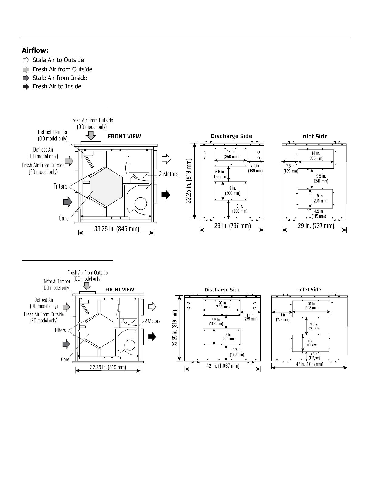
3 Dimensional Drawings .................................................................................................................................................... 4
4 The Integrated HVAC System.......................................................................................................................................... 5
5 The Integrated HVAC System.......................................................................................................................................... 2
6 Stale Air Return and Fresh Air Supply System ................................................................................................................ 3
7 Weatherhoods and Grilles .............................................................................................................................................. 4
8 Drain Connections........................................................................................................................................................... 5
9 Electrical Connections..................................................................................................................................................... 6
10 Function and Controls..................................................................................................................................................... 7
11 Main Wall Control ........................................................................................................................................................... 2
12 Main Wall Controls ......................................................................................................................................................... 2
13 Main Wall Control ........................................................................................................................................................... 2
14 Main Control (99-BC02/3/4) ........................................................................................................................................... 3
15 Main Control (99-500)..................................................................................................................................................... 4
16 Timers and Repeaters ..................................................................................................................................................... 5
16 Timers and Repeaters ..................................................................................................................................................... 6
16 Timers and Repeaters ..................................................................................................................................................... 7
16 Timers and Repeaters ..................................................................................................................................................... 8
17 Air Com Relays & Interlocking to a furnace/air handler ................................................................................................. 9
18 Reversing the Supply and Defrost Air Ports (DD Models only)..................................................................................... 10
19 Fan Defrost and Damper Defrost.................................................................................................................................. 11
20 Balancing the Airflows .................................................................................................................................................. 12
21 Balancing the Airflows .................................................................................................................................................. 13
22 Service and Maintenance.............................................................................................................................................. 14
22 Service and Maintenance.............................................................................................................................................. 15
23 Reverse Installation of the HRV .................................................................................................................................... 16
23 Reverse Installation of the HRV .................................................................................................................................... 17
24 Troubleshooting ............................................................................................................................................................ 18
24 Troubleshooting ............................................................................................................................................................ 19
25 Wiring Diagrams (455FD) .............................................................................................................................................. 20
25 Wiring Diagrams (650FD, 700FD, 1200FD).................................................................................................................... 21
25 Wiring Diagrams (455DD, 650DD, 700DD, 1200DD)..................................................................................................... 22
26 Warranty ....................................................................................................................................................................... 23