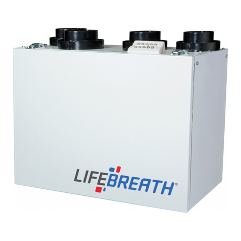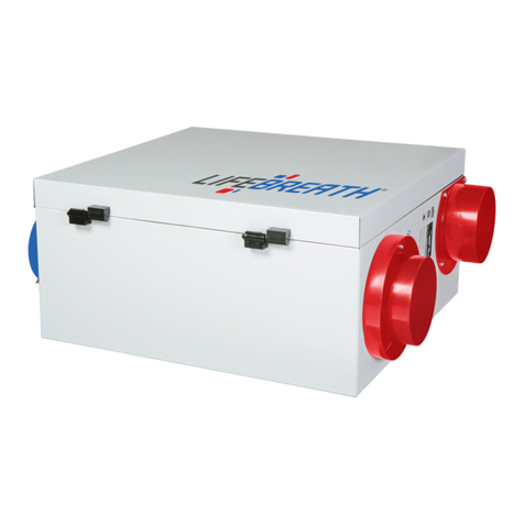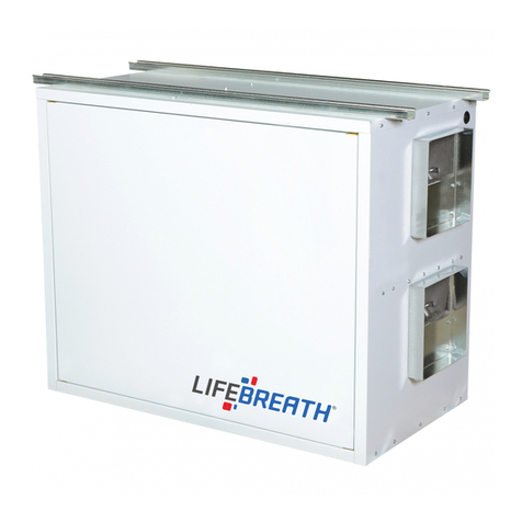
Table of Contents
Location .................................................................................................................................... 2
Pre-Installation Notes ................................................................................................................ 3
Simplified Installation (Return/Return Method) ............................................................................ 4
Partially Dedicated System ......................................................................................................... 5
Fully Dedicated System .............................................................................................................. 6
Hanging Straps .......................................................................................................................... 9
Drain Connection ......................................................................................................................10
Grilles ......................................................................................................................................12
Grille Fittings ............................................................................................................................ 13
Lifebreath Weatherhood............................................................................................................ 14
Weatherhood Requirements ...................................................................................................... 15
Main Control Installation ........................................................................................................... 16
Mechanical Timers Installation ................................................................................................... 17
Installation and Operation 20/40/60 Minute Timers: 99-DET01 and 99-20M01 ............................. 18
Installer Selectable High Speed Settings..................................................................................... 18
Dimensional Model Diagrams - 95/100/155 Models ..................................................................... 19
Dimensional Model Diagrams - 195/300/205 Models ................................................................... 20
Balancing the Airflows ............................................................................................................... 22
Determining the CFM ................................................................................................................ 23
Balancing Collar Instructions ..................................................................................................... 23
Balancing the Airflows with a Pitot Tube .................................................................................... 24
Balancing the Airflows Using the Door Ports ............................................................................... 25
Airflow Reference Chart - 155 Model .......................................................................................... 27
Airflow Reference Chart - 205 Model .......................................................................................... 28
Troubleshooting ....................................................................................................................... 30
2
Location - Installation Notes
Install the unit in a heated space that provides clearance for service access. A typical location is in
either a mechanical room or an area close to the outside wall within close proximity to where the
weatherhoods are mounted. If a basement area is inconvenient or non-existent, install the unit in a
utility room or laundry room. Attic installations are not recommended due to:
The complexity of work to install
Freezing conditions in the attic Difficulty of access for servicing and cleaning
If attic installation is necessary the unit must be situated in a conditioned space.
Leave sufficient clearance at the front of the access door for servicing the air filters and core. The
recommended clearance is a minimum of 25 in (635 mm) for opening and closing the door. Airia
provides four straps for hanging the unit from the basement floor joists.
Airflow Reference Chart - 100 Model .......................................................................................... 26
Optional duct configuration for models: 195DCS, 195ECM, and 300DCS ............................................. 7
Airflow Reference Chart - 65MAX Model..................................................................................... 29
Dimensional Model Diagrams - 65MAX Models............................................................................ 21
Drain Connection 65MAX........................................................................................................... 11
Mounting the 65MAX.................................................................................................................. 8

