www.LightingServicesInc.com Page 2 of 9 IS-0213_A 0616
Installing
the Fixture
with the
-00 Fitting
on an LSI
Track
FOR USE WITH LSI 3, 4, 5, 6, 8, AND 9 SERIES TRACK
INSTALLATION INSTRUCTIONS: The track must already
be installed according to code requirements. When installing
or using this track, basic safety precautions should always
be followed, including the following:
Read all instructions.
Do not install any part of a track less than 5 feet above the
floor (8 feet for 277V).
Do not install any fixture closer than 6 inches from any
curtain or similar combustible material.
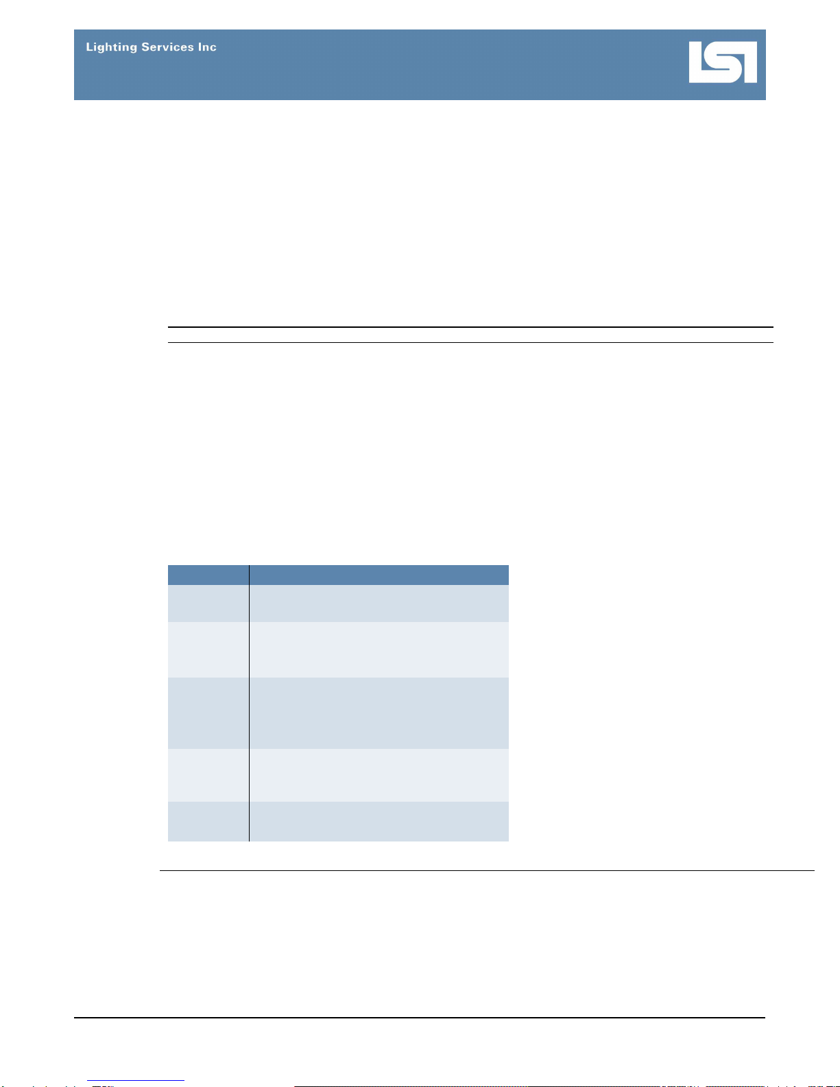
STEP ACTION
1 Flip the fitting switch off and open the fitting
handle (Fig. 1).
2 Are you using a one-circuit or two-circuit system?
If one-circuit, make sure the brass contacts that
protrude from the side of the fitting face the
copper busbars inside the track.
If two-circuit, inserting the fitting in one direction
connects to circuit one. Removing and
reversing the direction of the fitting connects to
circuit two.
3 Insert the fitting straight up into the track until fully
seated (Fig. 2).
4 Close the handle and flip the fitting switch on (Fig
3).
WARNING: Do not look directly at lit LED.
5 To remove the fitting, hold the fixture in place, flip
the fitting switch off, open the handle and pull the
fitting straight off the track.
Figure 1. Fitting with switch OFF
and handle OPEN.
Figure 2. Inserted fitting
Figure 3. Switch ON, fitting handle
closed
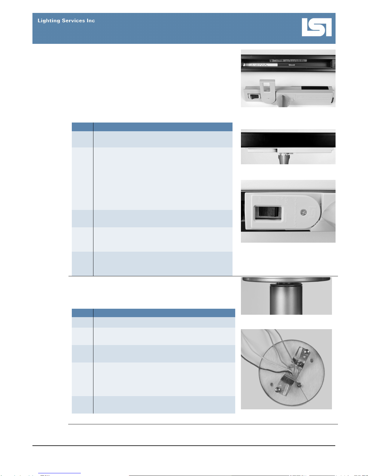
Installing
the Fixture
with a 5A
Canopy
Before Installing: Consult the code requirements for fixture
mounting. Mount the fixture to a ceiling constructed of non-
combustible material, away from any flammable materials.
STEP ACTION
1 Turn off all power to the fixture mount.
2 Unscrew the 2 supplied canopy mounting screws,
and remove the crossbar from the canopy (Fig. 4).
3 Attach the canopy crossbar (Fig. 5) to a ceiling
junction box with 2 screws (supplied by others).
4 Fasten the power wires (Fig. 5) from the junction
box to the fixture wires.
Note: Connect green to ground, black to the circuit
line, and white to neutral.
5 Attach the canopy to the ceiling with the 2 supplied
canopy mounting screws.
Figure 4. Fixture mounted on the
5A Canopy
Figure 5. Ground and power wires
with canopy crossbar