Lightline Lasertechnik Laserlink User manual

Preliminary Manual
1
Manual
Introduction
Dear customer,
thank you for choosing the Laserlink lasercontroller, which links lighting operators with showlasers in
real time.
The Laserlink is the 2nd Generation of the former successful Lightline DMX-Box.
Main feature is to operate a lasersystem easy as a lighting fixture from any lighting console.
For that DMX, ARTNET1 and RDM can be used.
Hence, the laserlink has up to 2 individual ILDA outputs being able to supply 2 independent scanning
systems with 16-bit XY-Scanning and 16-bit RGBO data as a standalone unit or can be mounted
directly into a lasersystem.
For automatic effects like rotations, all systems are synchronized by DMX protocol.
Another main feature is the possibility of using Syncronorm Depence2 WYSIWYG visualization. It is
fully integrated into the software without need of hardware.
As the standalone unit it is very small size and is very easy to integrate into your stage setup as there
is a mount for TV-Bolt or clamp and safety eye bolt.
Please, read the following safety notes carefully, especially before you connect the device to a laser
projector rated more than class 1.
1 Art-Net™ is Designed by and Copyright Artistic Licence Holdings Ltd.

Preliminary Manual
2
Content
Introduction ............................................................................................................................................. 1
Safety Notes ............................................................................................................................................ 4
Packaging List: ......................................................................................................................................... 6
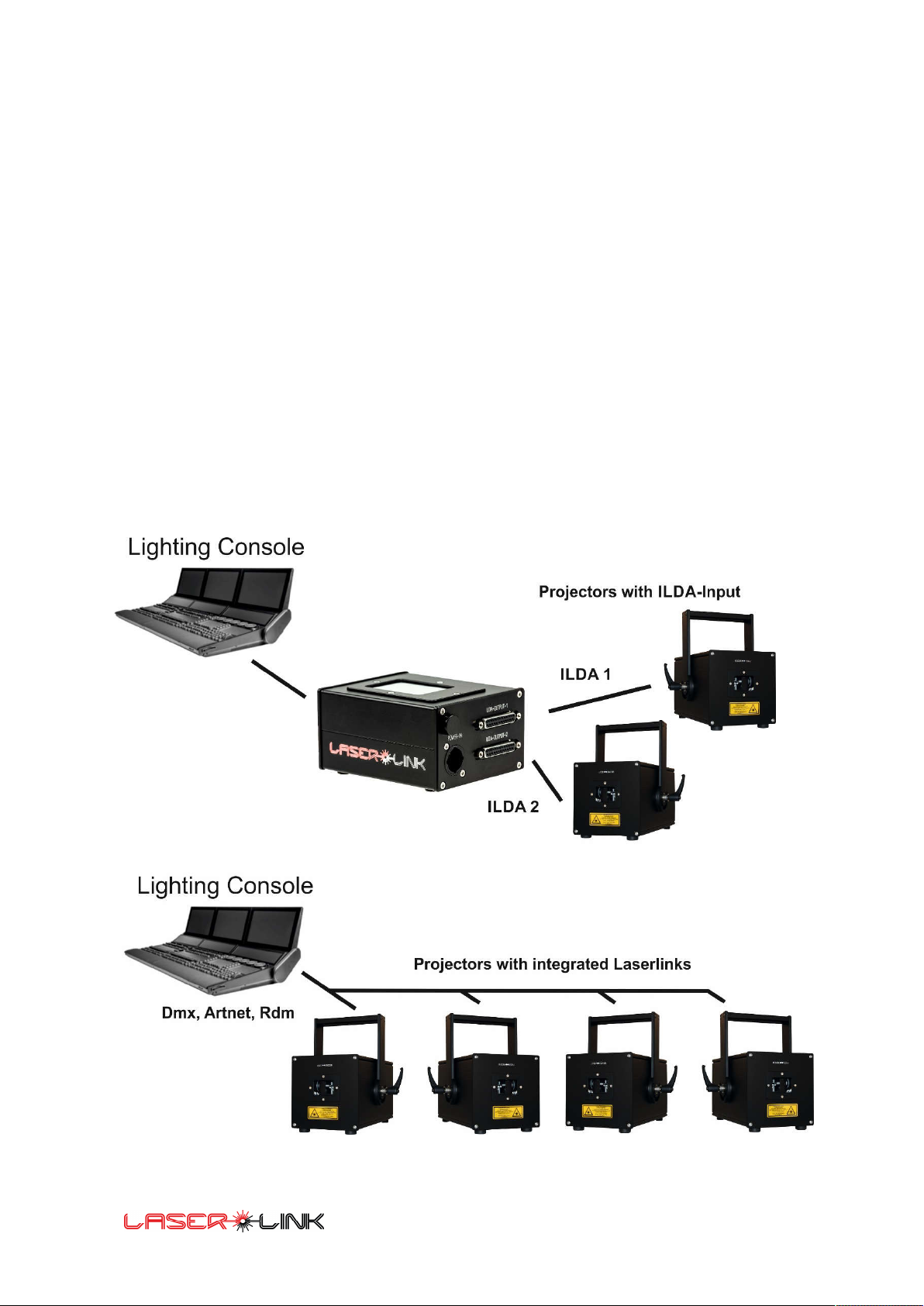
Installation of the system: ....................................................................................................................... 6
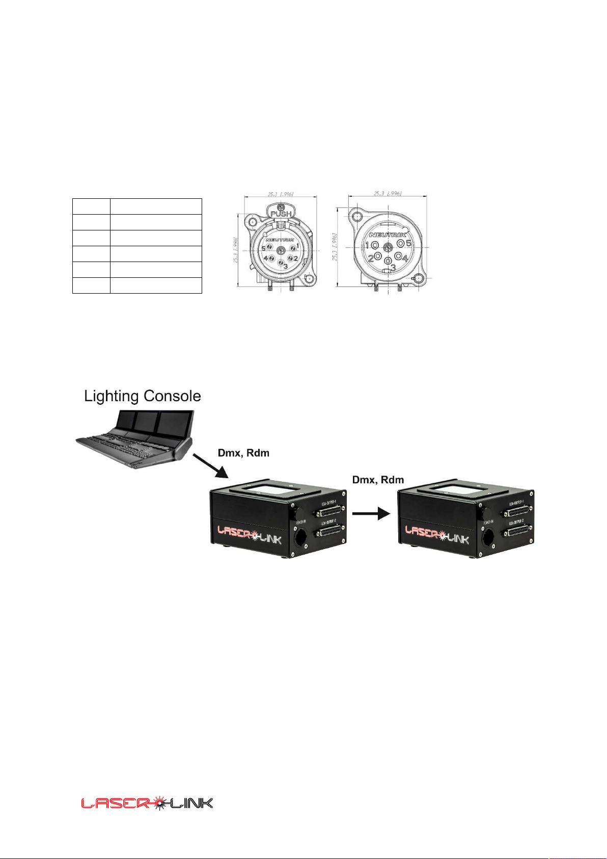
Laserlink PINOUT ..................................................................................................................................... 7
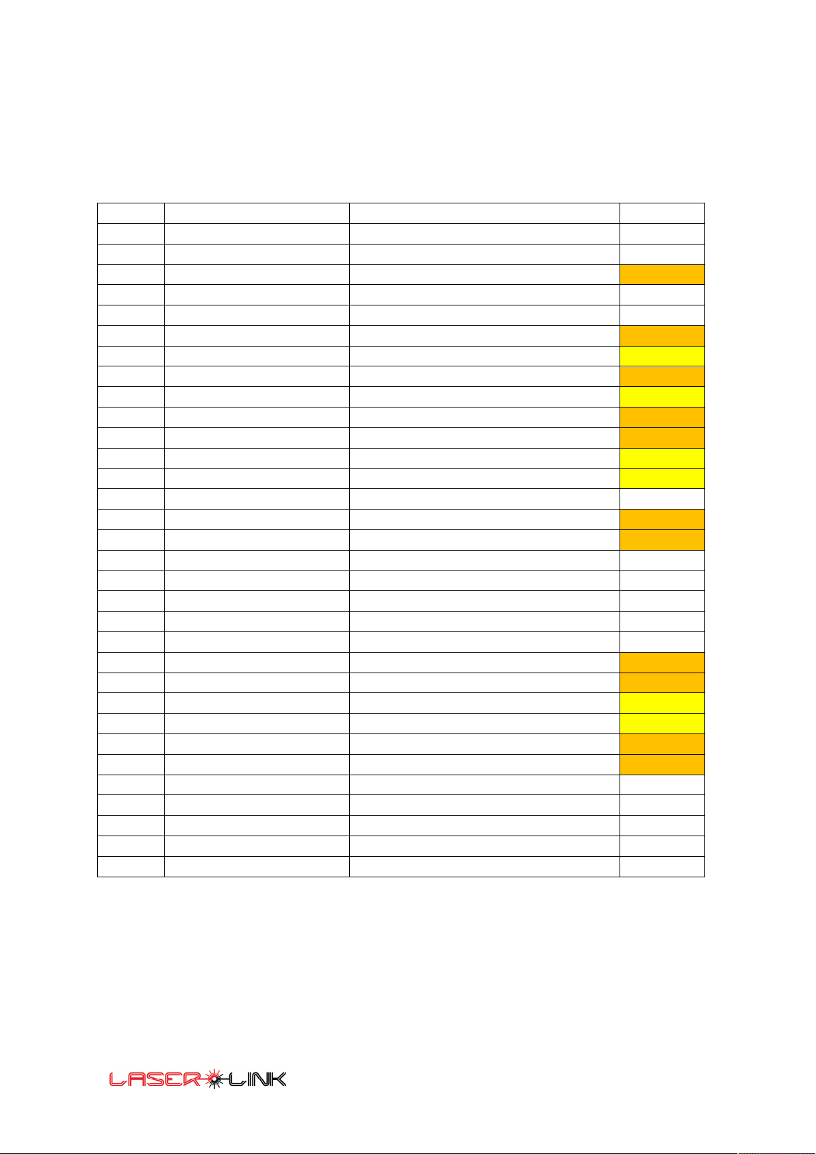
DMX Sheet for Fixture: .......................................................................................................................... 10
Patching: ................................................................................................................................................ 11
First startup: .......................................................................................................................................... 11
Adjustable values and value ranges. ..................................................................................................... 12
Main Screen ........................................................................................................................................... 13
CONTROL SETUP ................................................................................................................................ 14
Scanner Setup .................................................................................................................................... 17
System Setup ..................................................................................................................................... 20
Network Settings ............................................................................................................................... 21
Touchscreen Calibration .................................................................................................................... 22
Factory Settings ................................................................................................................................. 23
Error Log ............................................................................................................................................ 23
Update System .................................................................................................................................. 24
Reboot System .................................................................................................................................. 24
Testpicture ......................................................................................................................................... 25
Color calibration ................................................................................................................................ 31
Load/Save config ............................................................................................................................... 34
RDM operation ...................................................................................................................................... 35
General RDM Commands: ................................................................................................................. 35
RDM Commands Output 1: ............................................................................................................... 36
RDM Commands Output 2: ............................................................................................................... 37
DMX functionality: ................................................................................................................................. 38
Safety Channel ................................................................................................................................... 38
Service coarse 8-bit 0..255 ................................................................................................................ 38
Shutter/Strobe coarse 8-bit 0 .. 255 .................................................................................................. 39
Dimmer /Dimmer fine coarse 16-bit 0..65535 .................................................................................. 39
RED coarse linear 8-bit 0 .. 255 ......................................................................................................... 39
GREEN coarse linear 8-bit 0 .. 255 ..................................................................................................... 39
BLUE coarse linear 8-bit 0 .. 255 ........................................................................................................ 39

Preliminary Manual
3
Orange coarse linear 8-bit 0 .. 255 .................................................................................................... 39
PAN/ PAN fine coarse 16-bit 0 .. 65535 (- 32.768 .. 32767) ........................................................... 40
TILT/ TILT fine coarse 16-bit 0 .. 65535 (- 32.768 .. 32767) ........................................................... 40
Gobo coarse 8-bit 0 .. 255 ................................................................................................................. 40
ROT Z/ ROTZ fine coarse 16-bit 0..65535 (- 32.768 .. 32767) ........................................................ 42
Color1 Colorsegments coarse 8-bit 0 .. 255 ...................................................................................... 42
Color1 Colorspeed coarse 8-bit 0 .. 255 ............................................................................................ 44
Color2 Colorsegments coarse 8-bit 0 .. 255 ...................................................................................... 44
Color2 Colorspeed coarse 8-bit 0 .. 255 ............................................................................................ 46
ColorXFade coarse 8-bit 0 .. 255 ........................................................................................................ 46
ZOOM/ ZOOM fine coarse 16-bit 0 .. 65535 .................................................................................... 46
ROT X/ ROTX fine coarse 16-bit 0..65535 (- 32.768 .. 32767) ........................................................ 47
ROT Y/ ROTY fine coarse 16-bit 0 .. 65535 (- 32.768 .. 32767) ...................................................... 47
Modifier 1 Select coarse 8-bit 0 .. 255 .............................................................................................. 48
Modifier 1 Speed coarse 8-bit 0 .. 255 .............................................................................................. 49
Modifier 2 Select coarse 8-bit 0 .. 255 .............................................................................................. 50
Modifier 2 Speed coarse 8-bit 0 .. 255 .............................................................................................. 50
Delay/Point repeat coarse 8-bit 0 .. 255 ........................................................................................... 51
Laserlink Technical Data ........................................................................................................................ 52

Preliminary Manual
4
Safety Notes
Each person which is responsible for the installation, the use or service of this unit must be:
qualified
together with a laser: must have a "Laserschutzbeauftragtenschein" or must be a
certified laser-safety officer.
must follow the instructions in this manual.
WARNING!
Be careful when using the device. You risk an electrical shock from high voltage, if you touch the
wires!
Install and use according to the valid laser safety rules of your country.
The device has left our company in manufacturer proofed state. To maintain this status and
to ensure a permanent safe operation, it is absolutely necessary to follow the safety
instructions and warnings in this manual.
IMPORTANT!
Errors caused by not following these instructions are not covered by the warranty. The
manufacturer will not accept liability for any resulting defects or problems.
Keep the unit away from radiators or other heat sources!
If the unit has been exposed to tremendous temperature changes (e.g. after transportation),
do not turn it on immediately. The resulting condensation could damage the unit. Don`t
switch unit on until the device reaches room temperature.
This device belongs to protection class I. Therefore, it is imperative that the green/yellow
wire is connected to the earth contact of the plug. The electrical connection must be made
by a qualified person.
Make sure that the cable has never been squeezed or damaged by sharp objects. Check
the device and the cables regularly.
If the cable is damaged, it must be replaced immediately by the manufacturer, its service
agent or a qualified person in order to avoid danger.
Ensure that wires never come in contact with other wires! Handle the power cord and all
connections with caution!
Make sure that the line voltage is not higher than the voltage specified in this manual.
Disconnect the unit from the AC mains when it is not in use or when cleaning it.
Disconnect connections only by pulling the cable plug.

Preliminary Manual
5
Optical safety in use together with a connected lasersystem
RISK OF EYE INJURIES! RISK TO HEALTH!
Never stare into direct or scattered beam! Never point laser beams into the audience or
towards people. Do not point laser beams to animals.
Do not stare at laser light reflected from any surface.
Do not use laser in the presence of inflammable, explosives, or volatile solvents such as
alcohol or gasoline.
Direct eye contact with the output beam will cause serious injury and possible blindness.
Defects caused by modifications of the device by unqualified handling or an unqualified person
are not covered by the warranty.
Keep the product away from children and unskilled people.
There are no wear parts in the device. Maintenance and service must be performed only by an
authorized service partner.
Disconnect the unit from the AC mains when not in use or when cleaning it.
Laser beams might be also powerful enough to burn skin or clothing. Laser beams can ignite
volatile substances such as alcohol and can damage light-sensitive elements in video
cameras, and video beamer.

Preliminary Manual
6
Packaging List:
The Laserlink comes in following OEM configuration:
1 pieces of Laserlink
1 pieces of Neutrik Powercon True1 cable
Optional:
- Safety eye bolt, Safety 50cm
- Manfrotto clamp
- TV-bolt
- DMX Adapters
- Cat cable
- ILDA-Cable
Installation of the system:

Preliminary Manual
7
Laserlink PINOUT
Output connectors D-SUB 25 pol ILDA-Standard
It is recommended to use a standard 25 pol DSUB extension cable
Signal name: Pin Notes:
X + 1 0 to +10V
Y + 2 0V to 10V
Blanking + 3 Not connected
Interlock A 4 Connected Pin 17
R + 5 Red, 0V to + 5V
G + 6 Green, 0V to +5V
B + 7 Blue (typically 476nm), 0V to +5V
Deep Blue+ 8 Not connected
ORANGE+ 9 Orange, 0V to +5V
Cyan+ 10 Not connected
Z + 11 Not connected
Not connected 12 Not connected
Shutter 13 Shutter 0V off 5V on
X - 14 Connected to Ground pin 25
Y - 15 Connected to Ground pin 25
Blanking - 16 Not connected
Interlock B 17 Connected Pin 4
R - 18 Connected to Ground pin 25
G - 19 Connected to Ground pin 25
B - 20 Connected to Ground pin 25
Deep blue - 21 Not connected
Yellow - 22 Connected to Ground pin 25
Cyan - 23 Not connected
Z - 24 Not connected
Ground 25 GND

Preliminary Manual
8
DMX 512-Connection:
The laserlink is equipped with 5-pin XLR sockets for DMX in and DMX out.
The sockets are wired in parallel.
PINOUT DMX 5 pole Connector
Female Male
Pin Description
1 GND
2 Signal –
3 Signal +
4 not connected
5 not connected
For more than one Laserlink module you can daisychain:
Connect the DMX-Out from console to the DMX-IN of the first fixture. Then Connect DMX-Out to DMX-
IN of the second fixture and so on.
Attention: In some cases, the DMX-line has to be terminated with a 120OHM resistor at the last fixture
between Signal + and Signal –.
Note: The Laserlink is no Artnet Node. It’s not possible to go via Artnet to Laserlink No. 1 and from
there further on with DMX.

Preliminary Manual
9
Ethernet RJ45 connection
The Laserlink can be connected via Ethernet/Artnet to the NET socket. The Art-Net protocol is based
on UDP. Artnet has the advantage that you can send a larger number of channels than DMX 512.
For ARTNET communication you have to set an IP Address for identification and the Universe for the
DMX512 frame and channels.
The pinout of the Ethernet RJ45 connector is:
Pin Description
J1 TD+
J2 TD-
J3 RX+
J4 not connected
J5 not connected
J6 RX-
J7 not connected
J8 not connected
Connection to Mains
The Laserlink has an autoranging powersupply that goes from 100 to 240VAC and 50/60Hz.
Plug Marking
Connection
EU
US
L
Live
brown
black
N
Neutral
blue
white
Earth
Earth
Yellow/green
green
Note: For proper connection consult a qualified electrician.

Preliminary Manual
10
DMX Sheet for Fixture:
The Laserlink has one basic DMX-sheet which can be easily copied 4 times to get full access and
output of the Laserlink device:
Channel Laserlink Description Default
1 Safetychannel Safetychannel 0%
2 Servicechannel Output 1 Blanking options
3 Shutter/Strobe Shutter/ Strobe 100%
4 Dimmer 16 Bit 0%
5 Dimmer Fine
6 Red 0-255 100%
7 Green 0-255 100%
8 Blue 0-255 100%
9 Orange 0-255 100%
10 Pan PAN 16 bit 50%
11 Pan Fine
12 Tilt TILT 16 bit 50%
13 Tilt Fine
14 Gobo Maximum 255
15 RotZ Rotation Z 16-bit 50%
16 RotZ-Fine
17 Color 1 Colorsegments 255 Colorgobos 0-255 0
18 Color 1 Colorspeed Colorspeed 0-255 0
19 Color 2 Colorsegments 255 Colorgobos 0-255 0
20 Color 2 Colorspeed Colorspeed 0-255 0
21 Color X-Fade7mix Fade Colorprogram 1 into Colorprogram 2 0
22 Zoom ZOOM 16 Bit 50%
23 Zoom Fine
24 Rot X Rotation X 16 Bit 50%
25 Rot X Fine
26 Rot Y Rotation Y 16 Bit 50%
27 Rot Y Fine
28 Modifier 1 Animationseffects like Prism, Sparkle etc. 0
29 Modifier speed 1 Effect Speed 0
30 Modifier 2 Visible, Oscillate etc. 0
31 Modifier Speed 2 Effect Speed 0
32 Delay/Point Repeat Scanrate 0

Preliminary Manual
11
Patching:
If we assume the DMX start address is 1 then you will get following outputs:
Basic fixture 1: DMX 1-32 ILDA Channel 1 Object 1
Basic fixture 2: DMX 33-64 ILDA Channel 1 Object 2
The second object will be turned on when the Gobo channel is > 0 that means if Gobo channel > 0 the
second object output is sending to the scanner even if the dimmer channel is 0.
Basic fixture 3: DMX 65-96 ILDA Channel 2 Object 1
Basic fixture 4: DMX 97-128 ILDA Channel 2 Object 2
The second object will be turned on when the Gobo channel is > 0 that means if Gobo channel > 0 the
second object output is sending to the scanner even if the dimmer channel is 0.
First startup:
Connect all cables as in the diagram installation of the system with Lasers turned OFF.
When you connect the power plug the system boots up.
Please, enter the DMX start address or Art-Net settings.
Be sure that the lighting console has the right fixture and fixture patch:
To get something out of the box you do following in your lighting console:
With a function ready patched fixture:
Set the Dimmer channel less 10%
Shutter Channel 100%
Set Pan/Tilt to 50%
Set Zoom to 50%
Set RGBO channels to 100%
Choose GOBO > 0
Enable the Safety channel
A laser output should be achieved.

Preliminary Manual
12
Adjustable values and value ranges.
In the adjustment settings the values correspond the DMX values.
So a 8-bit DMX value can have the value range from 0..255
A 16-bit value has a range from 0..65535 or -32768..32767 respectively.
Usually, the scanner output is centered around coordinate XY=0,0. Therefore, the values reach from
-32768 to 32767. Hence the DMX values have an offset.

Preliminary Manual
13
Main Screen
In the main screen you can see the submenus, the Laserlink IP-Address and the MAC address.
Every Laserlink has a unique MAC address.
On the upper right you see the DMX address.
If there is no DMX signal connected or a DMX fault the DMX Address turns red.
In the bottom you see the Software version.
Then the following six submenus are accessible:
Control Setup
Scanner Setup
System Setup
Testpicture
Color Calib.
Load/Save Conf.
Control Setup
System Setup
Scanner Setup
Testpicture
Color Calib.
Load/Save Conf.
IP: 192.168.000.056
MAC: 80:1F:12:32:20:DA
DMX: 001

Preliminary Manual
14
CONTROL SETUP
If you press the Button Control Setup in Main menu you will access the Setup for the communication
settings. There you can choose between DMX, ARTNET and Static Data. With the checkbox RDM you
can enable the RDM Mode which is either used in DMX or ARTNET mode. In this menu the Safety
Channel can be disabled.
By choosing the Edit buttons, the settings for DMX, ARTNET and Static Data can be changed.
The DMX address can be entered directly by the Edit button or changed with the up and down
buttons.
Edit
Exit
Edit
Edit
DMX Control
Art-Net Control
Static Control
RDM
Safety Channel
safety function disabled
Exit
001
DMX Address:
Edit

Preliminary Manual
15
In the Art-Net setup, the ARTNET Universe, the ARTNET Net address and the ARTNET - Sub Net can
be changed.
The IP-Address of the Laserlink is derived from the Artnet specification and unique MAC address.
In the Static Data Setup pre-defined values can be stored that can be made active during boot. This
enables a fully standalone functionality. The Load DMX button reads the actual data (DMX or Art-Net).
Exit
00
00
00
Art-Net Universe:
Art-Net SubNet:
Art-Net Net:
IP: 192.168.000.056
MAC: 80:1F:12:32:20:DA
000
SafetyCh:
Edit
Exit
Ch: 1/2 | Obj: 1/2
Load DMX Steps:
100
000
Setup:
Edit
255
Shutter:
Edit
001
Dimmer:
Edit
<< >< >>
255
Red:
Edit
Exit
Ch: 1/2 | Obj: 1/2
Load DMX Steps:
100
255
Green:
Edit
255
Blue:
Edit
255
Orange:
Edit
<< >< >>
00000
Offset X:
Edit
Exit
Ch: 1/2 | Obj: 1/2
Load DMX Steps:
100
00000
Offset Y:
Edit
001
Gobo:
Edit
00000
RotZ:
Edit
<< >< >>
000
ColorProg1:
Edit
Exit
Ch: 1/2 | Obj: 1/2
Load DMX Steps:
100
000
ColorSpeed1:
Edit
000
ColorProg2:
Edit
000
ColorSpeed2:
Edit
<< >< >>

Preliminary Manual
16
000
ColorMix:
Edit
Exit
Ch: 1/2 | Obj: 1/2
Load DMX Steps:
100
32768
Size:
Edit
00000
RotX:
Edit
00000
RotY:
Edit
<< >< >>
000
Modifier1:
Edit
Exit
Ch: 1/2 | Obj: 1/2
Load DMX Steps:
100
000
ModParam1:
Edit
000
Modifier2:
Edit
000
ModParam2:
Edit
<< >< >>
000
RepeatDel:
Edit
Exit<< >
Ch: 1/2 | Obj: 1/2
Load DMX Steps:
100
000
-
Edit
000
-
Edit
000
-
Edit
< >>

Preliminary Manual
17
Scanner Setup
Scanner settings can be changed in Mainmenu Scanner Setup.
There you can see in the top Channel 1 /2. This represents output 1 Channel 2/2 represents output 2.
With the button Steps you can choose between 1, 10, 100 or 1000. This represents the value which
increase and decreases the values in the spin-boxes.
For example, if Step is set to 1 and Min Obj Size is 15 and you tab the decrease button 14 will be set.
The Scan Frequency is adjusted to fixed steps of 1000.
Then you can edit following parameters for each output:
Scan frequency:
Scan Frequency [Hz] can be selected between 10000 (slow scan speed) and 30000 (fast scan speed)
points per second.
Min Obj. [%]
The Min Obj. Size[%] is the minimum Size of the Gobo. Here it’s set to 15%. This is to prevent a single
beam from a Gobo with Zoom 0%. The laser output is faded out additionally for the last 1/3 percent
range of the Minimum Object Size.
Interpolation Length:
The Laserlink interpolates points into the Gobo output in order to make the output smoother.
The interpolation length is the maximum length between 2 Picture points before extra points will
added.
Smaller value here means increasing the number of output points.
Goto Channel 1 or 2 Choose increment / decrement
steps for the values

Preliminary Manual
18
With next you will access the Repeats Menu
Here you can adjust following parameters:
PreBlank On Repeats
It’s the time delay in repeats before the scanner reaches a blanked point and blanks because of his
mass inertia.
PreBlank Off Repeats
It’s the time delay before the blanking will be turned off.
PostBlank On Repeats
These are the numbers of repeats before the Picture will be shown.
PostBlank Off Repeats
These are the repeats which needed to delay the projection in order to put on the beam on again.
To start point repeats
After the output of the last picture point of a Gobo the scanner moves again to the start point of the
Gobo as fast as possible. Because of the mass inertia of the scanning mirror that takes some time.
To be sure that the scanner is again at the start point some start point repeats can be added.
Swap XY
Here you can swap the X with Y axis of the output. The picture will be turned 90 degrees.
Repeats:
ExitBack Next
Channel: 1/2
< >
Blank On:
Blank Off:
Picture:
Pre: Post:
00
00
06
06
06
19

Preliminary Manual
19
With next you will reach the new window for Visualisation Parameters.
LaserComProtocol
With this checkbox you can enable and disable the Ethernet Communication with Visualizers like
Reallizer and Depence2 from Syncronorm.
More Visualizers will follow in the future.
LaserDeviceID
Here you can give the Laseroutput a device ID which is necessary for Visualization.
ExitBack Next
Channel: 1/2
< >
Steps:
100
000
Laser Device ID:
LaserComProtocol

Preliminary Manual
20
System Setup
Here in this menu you can reach following settings:
Network settings
Calib. Touchscreen
Factory Settings
Error Log
With next you will reach following menu where you can choose between
Update System and Reboot System.
ExitBack Next
Network Settings
Calib. Touchscreen
Factory Settings
Error Log
ExitBack Next
Update System
Reboot System
Table of contents