10
Standard Components
In its standard configuration, the Light Viper 1832 is made up of the following primary
components.
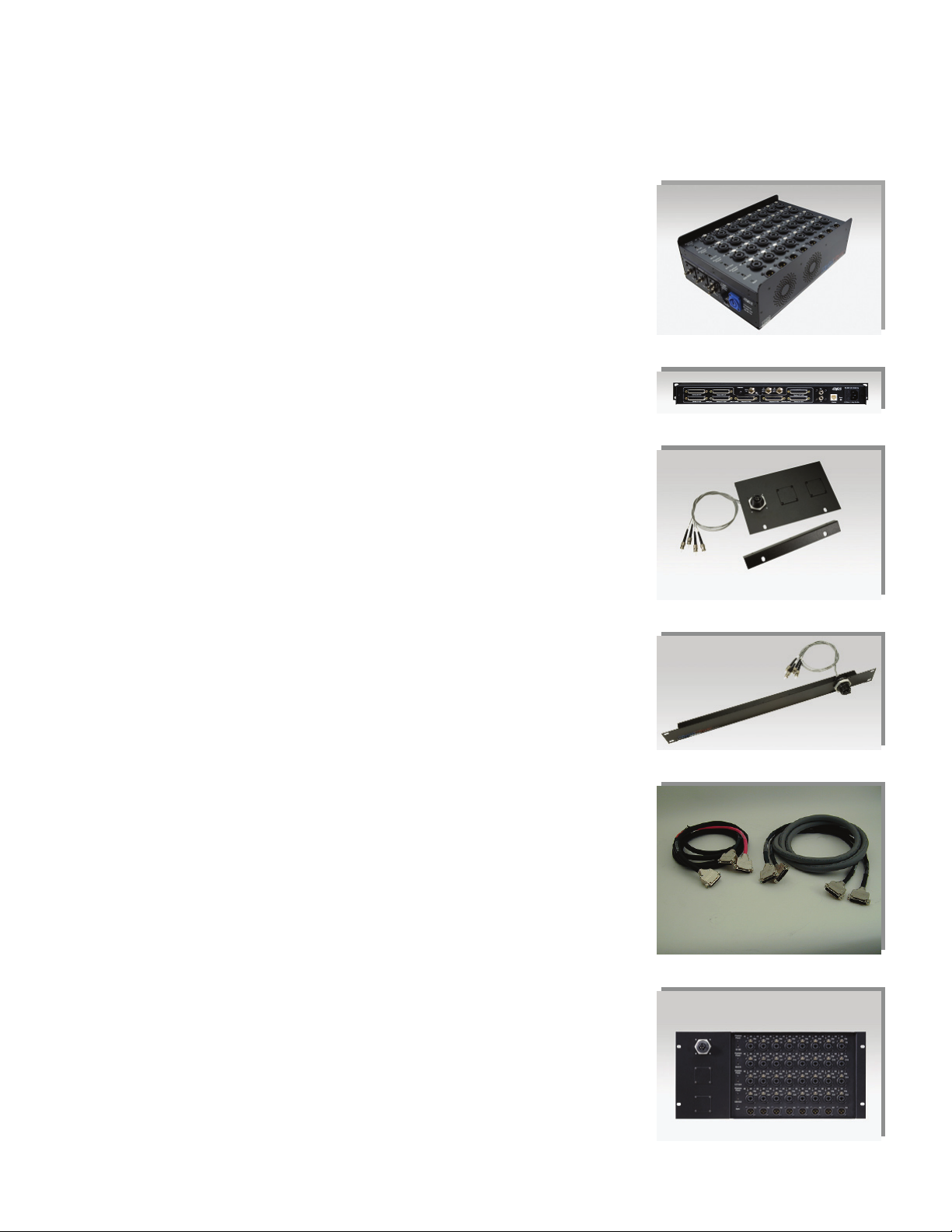
•The Stage Box (VIS-1832) — This is the box placed close to all the inputs. It can be
placed on the stage or rack mounted with the optional VER-1832 rack ears.
•The Mixer Box (VIM-1832) — The unit should be mounted in a rack close to the
primary (FOH) mixing console
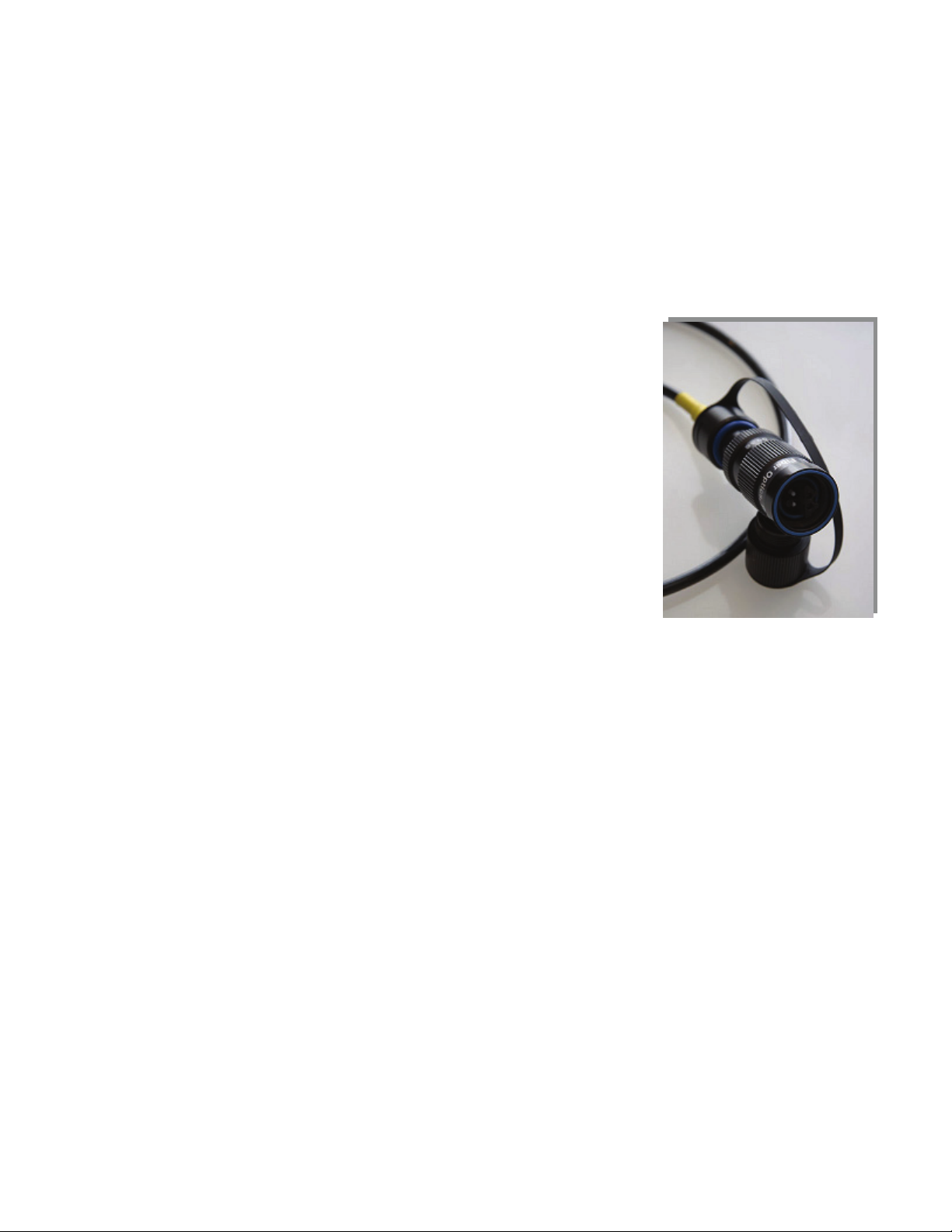
•The Fiber Cable (TFC-0000-04) — The lightweight “tactical grade” fiber ‘cable’ that
carries the digital signal between the stage and mixer boxes. For installation use, either
PVC or Plenum rated fiber is recommended (VFC-0000-D, VFC-0000-DP).
•TAC-4 Connector Panels – (VPL-11, VPL-12, VPL-13) – These 1U rack panels contain
(1), (2), or (3) panel mount TAC-4 connectors mounted respectively and allow
connection between tactical grade fiber to the ST connectors on the VIM units.
•Rack Ears – (VER-1832-T1, T2 or T3) These rack mount kits for the VIS-1832 have 1, 2 or
3 panel mount TAC-4 connectors mounted respectively and allow connection between
tactical grade fiber to the ST connectors on the VIS units. See page 20 for more
information.
•Send / Return Cables (VCB-ADXM, VCB-ADXF) — These cables connect the Mixer Box
to the analog inputs/outputs of your mixer. If you are connecting to a Yamaha digital
console through the Yamaha “Y” cards, you would use VCB-DDMY and VCB-DDMYIO
cables. A variety of cables to connect to other digital consoles and devices are also
available.
Optional Components
Additional components can be added to the Light Viper 1832 for increased functionality.
•Additional Send Box(es) (VIM-1032) – The VIM-1032 is similar to the VIM-1832 mixer box in
that itprovides a parallel setof the snake’s 32 input channels, via an additional Fiber Cable, in
applications where you need splits – for recording, broadcast, or monitor mixing. The VIS-
1832 Stage Box can be fit with two “split” connectors for a total of three (1 VIM-1832 (Primary)
+ 2 VIM-1032 (splits) outputs.
•Additional Analog Fan Out Cable(s) (VCB-ADXM / VCB-ADXF) – These fan out cables are
necessary for connecting additional mixer boxes (VIS-1832 and VIS-1032) to your analog
equipment. Youneed(4) VCB-ADXM for each VIM-1832 or VIM-1032 mixer boxes in the
system. The VIM-1832 also requires (1) VCB-ADXF (female) fan out toaccess the returns.
•Additional DigitalCables – To connect AES digital directly into a Yamaha PM5D, DM2000,
DM 1000 or M7, you need (2) optional cablesfor each 32x8 system. (1) DDMY and (1) DDMYIO
will allow a 32x8 connection into the Yamaha MY16AE cards. Optional cables are available to
interface with ProTools and other types of devices andvarious connector configurations.
•Ethernet Control – Add the optional ETH-1832 (pair) option to any Stage / FOH path, and
control a variety of Ethernet based gear on stage from the FOH position.
•Additional Fiber Cable(s) – Forlive production, TFC-0000-04 tactical grade fiber with TAC-4
Connector terminations is required between the stage box (VIS-1832) and all mixer boxes
(VIS-1832 and VIS-1032). For installations where the fiber will be pulled through conduit, either
VFC-0000-D (PVC fiber) or VFC-0000-DP (Plenum rated fiber) with ST connector terminations is
recommended. There is also an option for a “Pulling Eye” which can be specified by adding an
“E” tothe part numbers above (VFC-0000-DE; VFC-0000-DPE). This option includes a strain
reliefand pulling eye on one end of the fiber optic cable.
•Stage Box Mounting Hardware – The optional VER-1832 rack mount can be utilized in
applications where the stagebox (VIS-1832) will be rack mounted. The VER-1832-T1, T2 and T3
rack mount kits include panel mount TAC-4 connectors in quantities of 1, 2, and 3 respectively.
The rack ears can also be fitwith Neutrik“OpticalCon” panel mount connectors. The part
numbersare VER-1832-T1-OC, T2-OC, and T3-OCrespectively.
•TAC-4 and OpticalCon connectors can also be fit directly on the chassis ofthe VIS-1832, VIM-
1832 and VIM-1032, in applications such as these, rack ears and VPL panels are not required.