Liivatera Through-Zero VCO User manual

Through'Zero*VCO*Manual*0.1*
1*
!
Through-Zero Voltage-
Controlled Oscillator
!
!
!
!
!
!
!
!
!
!
!
!
!
Liivatera OÜ
Rävala pst. 8, A211
10143 Tallinn
Harjumaa
Estonia
T: +372 637 6441
T: +44 5603 010854

2*
Through'Zero*VCO*Manual*0.1*
!
Contents!
Introduction*.........................................................................*3!
Through(Zero!Frequency(Modulation.!.....................................................!3!
Reversing!Sync.!...................................................................................................!3!
Pulse(Width!Modulation.!................................................................................!3!
VCO!and!LFO!in!a!single!module.!.................................................................!3!
Key!Data!.................................................................................................................!3!
Installing*The*Module*...........................................................*4!
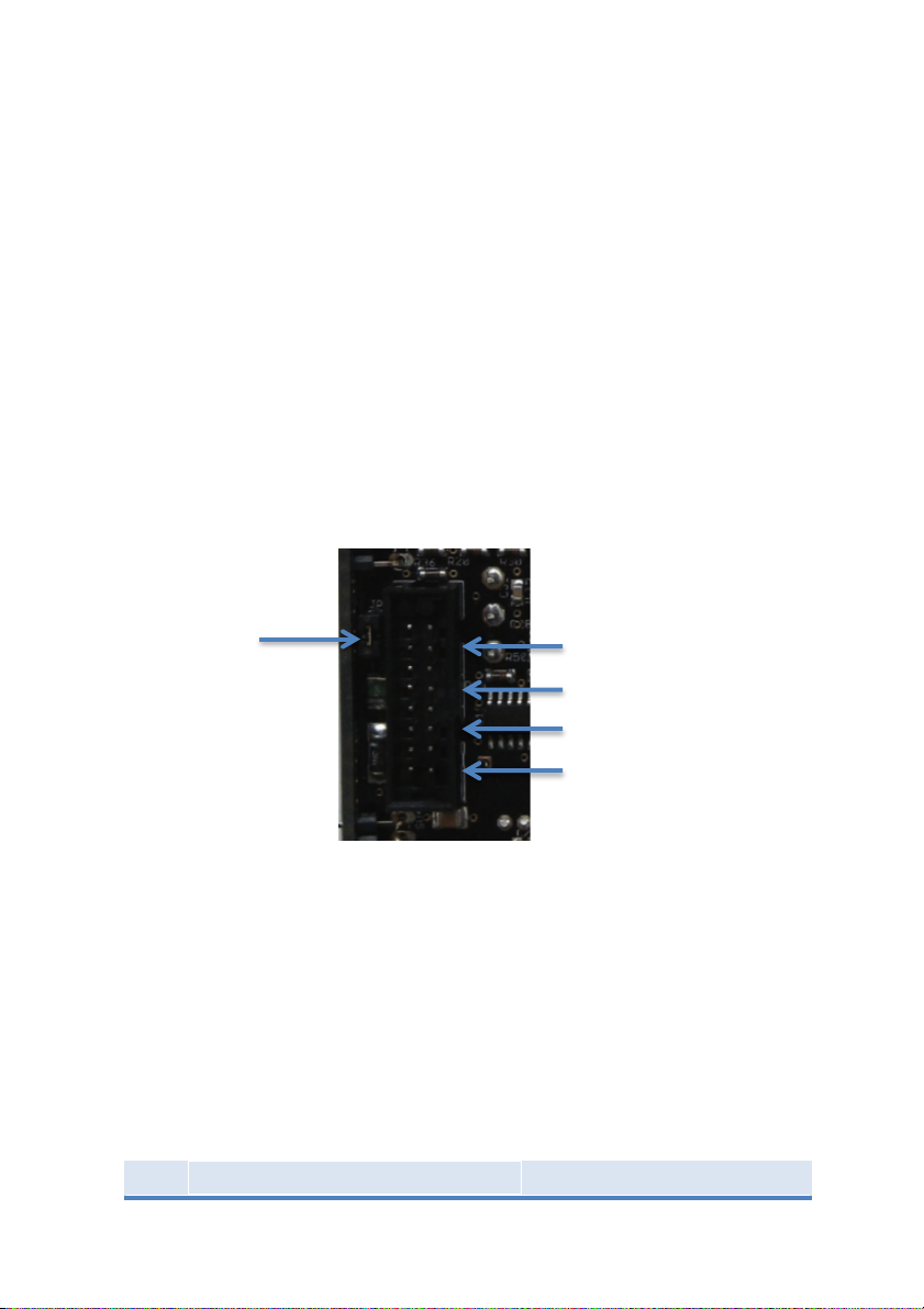
Connecting!Power!..............................................................................................!4!
Selecting!CV!Source!...........................................................................................!4!
Fitting!the!Module!in!the!Rack!.....................................................................!5!
Getting*Started*.....................................................................*6!
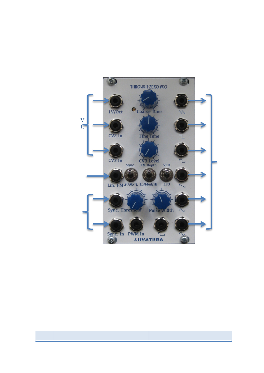
Connecting!to!a!CV!Source!.............................................................................!7!
VCO!Outputs!.........................................................................................................!7!
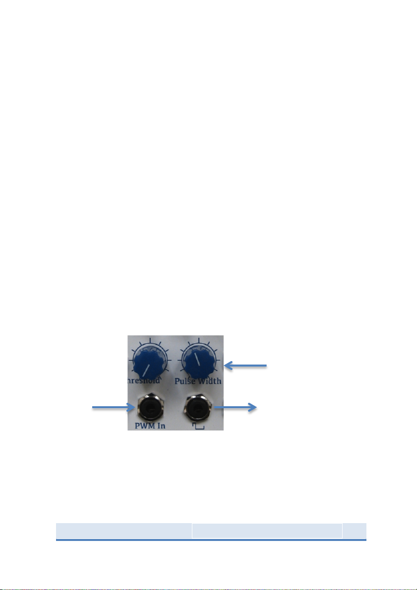
Pulse(Width!Modulation!.................................................................................!7!
Linear!FM!...............................................................................................................!7!
Through(Zero!FM!...............................................................................................!8!
Reversing!Sync.!...................................................................................................!8!
Calibration*...........................................................................*9!
Saw!Offset!..............................................................................................................!9!
1(volt/octave!Scaling!........................................................................................!9!
!
!
!

Through'Zero*VCO*Manual*0.1*
3*
!
Introduction*
This VCO uses a triangle-core design, but the true character comes
from the modulation capabilities.
Through'Zero*Frequency'Modulation.**
Wideband FM produces rich, inharmonic tones. Three switchable
sensitivity settings offer everything from simple vibrato to complex
tones.
Reversing*Sync.**
The direction of integration in the VCO core can be reversed on the
rising, falling and rising & falling edges of a signal. The trigger
threshold is set by the sum of a front-panel control and external CV,
so the sync. can be modulated to modify the tone of the VCO.
Pulse'Width*Modulation.**
The pulse output can be modulated from 0 to 100% with a dedicated
PWM input.
VCO*and*LFO*in*a*single*module.**
The frequency of the VCO can be reduced by a factor of 100 with a
switch on the front panel.
Key*Data*
Module Depth:
22mm
Power Connector:
Doepfer 16-pin shrouded
header
Current
Consumption:
+12 Volts, 65mA
-12 Volts, 60mA
Reverse-Power
Protection:
Yes
Panel Width:
14HP (70.8mm)

4*
Through'Zero*VCO*Manual*0.1*
!
Installing*The*Module*
Connecting*Power*
The module is supplied with a 12-inch ribbon-cable to connect it to
the power distribution bus in your cabinet. The keyed socket on the
module ensures that the cable can only be installed one way, with the
red stripe of the cable towards the bottom of the module. The 16-way
plug on the far end of the cable should be orientated with the red
stripe on the cable connecting to the -12-Volt pins on the distribution
board.
It is advisable to power the module briefly before fixing it in the
cabinet to confirm that the cable is fitted correctly. When doing this
ensure that the module is not placed on a conducting surface. The
internal protection circuits will prevent any damage to the module
should the cable be connected incorrectly.
Selecting*CV*Source*
When fitted, the Bus CV jumper connects pins 13 and 14 of the power
connector to the CV summer. The VCO will then track the CV on the
power bus without patching, simplifying the connections to the
module. If this feature is not wanted then removing the jumper
isolates these pins and the user can patch the required CV through
the front panel jacks.
-12 Volts
+12 Volts
GND
Bus CV
Bus CV
Jumper

Through'Zero*VCO*Manual*0.1*
5*
!
Fitting*the*Module*in*the*Rack*
The module is supplied with four M3 bolts and two transparent nylon
washers. Place the module in the rack and, if you are using threaded
guide-rails, align the mounting holes in the front-panel with the
holes in the rails. Place the nylon washers on the bolts, and screw the
bolts into the rail. The washers will prevent marking on the panel
from the bolts, but don’t over-tighten them as this will make
removing the module at a later date more difficult.

6*
Through'Zero*VCO*Manual*0.1*
!
Getting*Started*
Please refer to the ‘Installing Your Module’ section before
progressing to this chapter.
!
The general layout of the module is that inputs are on the left side of
the module and outputs on the right. The three pots at the top of the
module control frequency, and once set are unlikely to need
modification while using the module. It is also unlikely that the
switches will be used interactively.
Sync.
Input and
Offset
Control
VCO
Outputs
3 Exponential CV
Inputs. 2 1V/Oct,
1 Variable
!
!
!
Linear FM &
Through-Zero
Modulation

Through'Zero*VCO*Manual*0.1*
7*
!
Connecting*to*a*CV*Source*
The main tuning CV can be connected either through the front panel
jacks (the 1-v/Oct input is preferred) or via the 16-pin header on the
back of the module.
The other CV inputs have an exponential control relationship and can
be used to, for example, add an offset to the VCO tuning when
multiple VCO’s are played together. This can be particularly effective
with a sequencer where a repeating pattern can be transposed to a
different frequency each time the pattern is repeated.
VCO*Outputs*
The VCO module provides all the usual waveforms – Sine, Triangle,
Saw, Square and Pulse. In addition to these there are half-frequency
square and double-frequency saw outputs that extend the range of
the oscillator by two octaves. Each output is 10Vp-p with a 1k output
impedance.
Pulse'Width*Modulation*
The pulse output can be varied both manually and by an external
modulation source. When an external source is used the ‘Pulse
Width’ control sets the point that the output is modulated around so
that quite subtle PWM effects can be achieved.
Linear*FM*
The linear FM input is AC coupled with a cut-off frequency of 3Hz, to
ensure that modulation signals connected to this input will not
detune the VCO.
Initial Pulse Width
Pulse Output
Pulse-Width
Modulation
Input

8*
Through'Zero*VCO*Manual*0.1*
!
For ‘traditional’ FM effects such as vibrato this is best achieved with
the ‘FM Depth’ switch up, and a 10-vp-p modulating signal will sweep
the VCO frequency from 0Hz to twice its initial frequency.
Through'Zero*FM*
With the ‘FM Depth’ switch set to either the centre or bottom
positions the FM sensitivity is increased by a factor of 3 or 10
respectively. This increases the modulation range for a 10-vp-p
modulating signal as follows –
Switch Setting
Lowest Frequency
Highest Frequency
‘Lo’
0
2 F0
‘Med’
-2F0
4 F0
‘Hi’
-9 F0
11 F0
Reversing*Sync.*
!
VCOFM Depth:
Up for vibrato
Centre & Down for through-Zero FM

Through'Zero*VCO*Manual*0.1*
9*
!
Calibration*
There are two trimmers that need adjustment for correct operation of
this module.
Saw*Offset*
The Saw wave is generated from the double-frequency saw by
summing it with the Square wave. This trimmer adjusts the amount
of square wave added to eliminate a discontinuity as the waveform
crosses zero-volts. It is best adjusted while monitoring the Saw
output on an oscilloscope, however it can be adjusted roughly ‘by ear’
if necessary. This is trimmed during manufacture and it is unlikely to
need further adjustment.
1'volt/octave*Scaling*
The module is supplied pre-trimmed for 1-volt/octave scaling on the
input connected to the Doepfer 16-pin header, but users may wish to
adjust this to match their specific CV source.
Before starting, if the CV signal on the header is used then ensure
that the supplied jumper is fitted. If the 1-volt/octave jack on the
front panel is the primary CV input then the jumper may be removed.
The module must be powered and left for the temperature to stabilize
to make calibration easier.
The calibration procedure outlined assumes that a keyboard is used
as the CV source, but the method can easily be modified for other
controllers.

10*
Through'Zero*VCO*Manual*0.1*
!
Equipment used: Frequency counter, trimmer tool.!!
!
Calibration Procedure
1. Connect the CV source (keyboard) to the VCO, either via the
16-pin header of front panel jack, and connect the frequency
counter to the Square wave output.
2. Play A4 on the keyboard and adjust the Coarse and Fine
knobs until the VCO is generating a tone at 440Hz.
3. Play A6 on the keyboard and trim the scaling adjustment
trimmer until the frequency counter reads 1760Hz.
4. Repeat steps 2 and 3 until the trimmer no longer needs
adjustment.
5. Check the scaling across the keyboard range to verify the
scaling accuracy. The frequency error should be <0.1% over 8
or more octaves.
!
Scaling
Adjustment
Table of contents