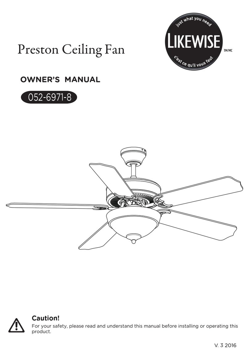
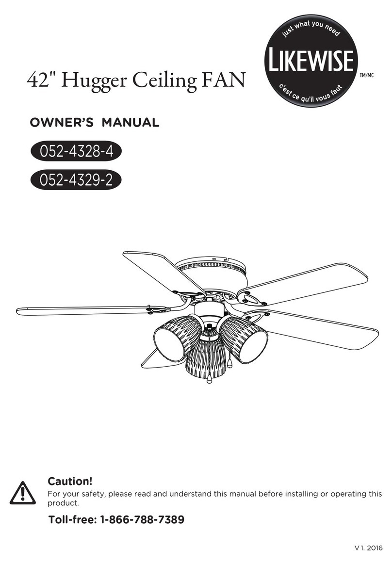
Likewise 052-4316-2 User manual

42" Hugger Ceiling FAN
OWNER’S MANUAL
052-4316-2
Caution!
For your safety, please read and understand this manual before installing or operating this
V3. 2016
product.

Table of Contents
Technical Data
Important Safety Instructions
Parts List
Parts Locations
Before Installation
Installation
Operation
Care and Maintenance
Troubleshooting
Environmental Protection
Warranty
2
2
3
4
5
6-7
7-11
11-12
12
13
14
14
Operating voltage
Power consumption
Bulbs
120 V, 60 Hz
Fan only: 45 W (Maximum)
One E12 candelabra-base bulb (60 W maximum)
Whenitcomestoproductsforyourhome,it’sessential
theystandup totherealitiesofeverydayfamilylife.
TM
Designedwithyourfamilyinmind,ForLiving products
combinetimelessstyleandfamily-friendlyfeatures.
Nowyoucanfocusonwhat’simportant creating
lastingmemorieswithyourfamily.
2

WARNING! To avoid possible electric shock, switch off the power supply at the main fuse or
circuit breaker box before installing, servicing or cleaning.
DO NOT use the ceiling fan if it shows any sign of damage or if it has been dropped.
DO NOT expose the ceiling fan to rain or moisture. Do not operate it outdoors or with wet hands.
DO NOT operate the fan without blades.
DO NOT insert foreign objects between the rotating blades.
Pay special attention to the fan and blades when cleaning, painting or working near the fan.
The fan must be mounted with the blades at least 6' 10"(2.1 m) above the floor to prevent accidental
contact with the blades.
To prevent injury, make sure the blades are not bent and that there are no objects within the rotation area.
Do not reverse the rotation until blades have come to a complete stop.
All installation should be conducted in accordance with the national and local wiring codes, including fire-
-rated construction. Use the national codes if local codes do not exist.
The ceiling fan must be grounded as a precaution against possible electric shock. Electrical installation
should be done or approved by a licensed electrician.
Follow the recommended instructions for the proper method of wiring your ceiling fan. If you do not know
enough about electrical wiring, have the fan installed by a licensed electrician.
The outlet box and joist must be securely mounted and capable of reliably supporting at least 50 —100 lb
(22.7 — 45.5 kg).
Use only outlet boxes marked “Acceptable for Fan Support ” and use the supplied outlet box screws.
Most outlet boxes commonly used to support light fixtures are not acceptable for fan support and may
need to be replaced. Consult a qualified electrician if in doubt.
The fan must not be installed in a ceiling thermally insulated to a value greater than R40.
To reduce the risk of electric shock, this fan must be installed with a wall-isolating control/switch.
All screws must be checked and re-tightened where necessary.
,
WARNING!
Only use the parts and accessories supplied with this product, or specifically designated
for use with this product by the manufacturer. Substitution with parts and accessories not
designated by the manufacturer could result in personal injury or property damage.
NOTE:
This ceiling fan is designed for household use only and not for commercial applications.
No responsibility is accepted for damage resulting from improper use or non-compliance
with the instructions.
The important precautions, safeguards, and instructions appearing in this manual are not
meant to cover all possible situations. It must be understood that common sense and caution
are factors that cannot be built into the product.
WARNING!
To avoid possible electric shock, switch off the power supply at the main fuse or circuit
breaker box before installing, servicing, or cleaning
SAVE THESE INSTRUCTIONS.
WARNING!
Not suitable for use with SOLID-STATE speed controls.
IMPORTANT: RETAIN FOR FUTURE REFERENCE, AND READ CAREFULLY.
3
IMPORTANT SAFETY INSTRUCTIONS

Part Description Illustration QTY Part Description Illustration QTY
1,5,
12
Mounting
bracket
Fan motor
assembly
11 Motor
housing
Blade
15
16
20
Blade
bracket
Glass shade
4
1
1
1
4
1
2,3
2,3
_
_
_
_
ST4.8 x 38
Wood screw
with flat
washer
2
1
2
13
1
3
13
2
“J” hook
Sm4 X 25
Outlet box
screw with
lock washer
14
13
M5 X 12
blade screw
Wire
connector
Above parts listed in the right column are
packed in hardware bag. (Hardware not
shown to actual size.)
No
t
es:
G1/4” X 8
Extra blade
bracket
screw with
split washer
Pull chain
with fob
Hexagon nut
with flat
washer
4,5,6,
7,8,9,
10,17,
18,19
1
Zip tie
_
_1
Extra light
kit screw
4
PARTS LIST

QTY
1
2
2
1
3
1
1
1
1
1
1
4
12
12
4
4
8
1
3
1
NO. Description
1
2
3
4
5
6
7
8
9
10
11
12
13
14
15
16
17
18
19
20
3
L
2
1
3
L
2
1
Mounting Bracket
Lock Washer
Wood Screw/ Outlet Box Screw
Motor Support Bar
Mounting Screw
Motor
Switch Housing
Reverse Switch
Fan Pull Chain
Light Pull Chain
Motor Housing
Motor Housing Screw
Hexagon Nut
Blade Screw
Blade
Blade Bracket
Blade Bracket Screw
Light Kit
Light Kit Screw
Glass Shade
Flat Washer/
5
PARTS LOCATIONS

WARNING!
Read each step carefully before beginning any installation and make sure you understand
each step.
Keep children and pets away during installation.
Keep fingers away from places where they can be pinched or injured.
Tools Needed for Assembly (not supplied):
1 x star-head screwdriver
1 x flat screwdriver
1 x wrench
1 x stepladder
1 x wire stripper/pliers
1 x electrical tape
Materials
Unpacking Instructions
Unpack and inspect carefully to make sure all parts are included and not damaged (fig. 1).
Place all parts from the box on a working space in a cleared area.
WARNING!
WARNING!
Do not install or use the ceiling fan if any part is damaged or missing.
To avoid possible electric shock, switch off the power supply at the main fuse or
circuit breaker box before installing, servicing or cleaning.
Switch off the power supply at the main fuse or circuit breaker box to avoid possible electric shock
(fig. 2).
Materials
Wiring, outlet box and box connectors must be of the type required by the local code. The minimum wire
should be a three-conductor (two-wire with ground) of the following sizes:
Wire Length Wire Size (A.W.G.)
Up to 50' (15 m)
50-100' (15-30 m)
14
12
6

Choosing a Location for the Ceiling Fan
Choose a location where there is a high enough
ceiling clearance, at least 6' 10"( 2.1 m) between the
floor and the blades (fig. 3).
For effective air circulation, fans should be located
in the centre of the room, or a minimum of 32”
(81.3 cm) from adjacent walls or obstructions.
CAUTION! If there is a light fixture at
your
fixture first. Before removal, switch
off the power supply at the main fuse
or circuit breaker box.
chosen location, remove the light
1. Installing Mounting Bracket
WARNING!
The outlet box and joist must be securely mounted and capable of reliably supporting at
least 50 — 100 lb (22.7 — 45.5 kg).
To reduce the risk of electric shock, mount the fan only to an outlet box marked
“Acceptable for Fan Support ” and use the supplied outlet box screws. Most outlet boxes
commonly used to support light fixtures are not acceptable for fan support and may need to
be replaced. Consult a qualified electrician if in doubt.
,
Secure the mounting bracket (1) to an outlet box marked “Acceptable for Fan Support ” using outlet box
screws (fig. 4).
Insert the “T” bar end of the motor support bar (4) through the rectangular opening on the mounting
bracket (1) for hands-free wiring and for motor assembly (fig. 5).
,
6' 10"( 2.1
7
INSTALLATION

Normal masonry ceiling Wooden ceiling
Securely attach the mounting bracket (1) to an
outlet box marked “Acceptable for Fan
Support,” using the supplied outlet box screws
w(3) ith lock washers (2) (fig. 6).
Drill two mounting holes in the ceiling joist.
Securely attach the mounting bracket (1) to the
ceiling, using two sets of long wood screws (3)
with flat washers (2) (fig. 7).
WARNING! The mounting bracket (1) must sit firmly against the outlet box. If the outlet box is
recessed, remove the wall board until the mounting bracket (1) comes into contact with the
box. If bracket and/or outlet box are not securely attached, the fan could wobble or fall.
CAUTION!
Before drilling, ensure there are no electrical wires or water pipes behind the drill spots.
While drilling, we recommend wearing protective goggles and hearing protection.
2. Wiring Instructions
WARNING!
All wiring must be in accordance with national and local electrical codes including fire-
rated construction. If you are unfamiliar with wiring, consult a qualified electrician.
If you are not sure whether the electrical outlet box and fan are grounded, contact a
licensed electrician for advice. These parts must be grounded!
To avoid possible electric shock, switch off the power supply at the main fuse or circuit
breaker box before installing, servicing or cleaning.
Your outlet box should have three wires. If they are not there, contact a certified electrician to set this part up.
Match up and connect wires from the ceiling fan to the wires from your outlet box according to the chart
below:
Connect with wire connector On fan In outlet box
Ground and ground
Motor, light and live
Neutral and neutral
Ground wire (green)
Motor wire (black)
light wire (blue)
Neutral wire (white)
Ground wire
(typically copper or green)
Live wire (typically black)
Neutral wire (white)
8
INSTALLATION

While connecting wires, make sure to:
Match up the wires first.
Hold the bare metal leads together and twist until tight.
Insert the twisted ends into a wire connector and turn the wire connector until tight (fig. 8).
After all connections are done, turn the splices upward and push them carefully upward through the
mounting bracket (1) into the outlet box.
Spread the wires apart so that the green and white wires are on one side of the outlet box and the black
and blue wires are on the other side of the outlet box.
WARNING! Be sure no bare wire or wire strands are visible after making connections.
Note: The silver cord is only a safety cable (fig. 9a ).
You can wrap it over the mounting bracket (1) and
loop it into the hook on the mounting bracket (1) or,
alternatively, secure it to the ceiling using the
provided “J” hook and zip tie (fig. 9b).
Connect the motor wire (black) and light wire (blue) from the fan to the live wire from the outlet box.
Connect the ground wire (green) from the fan to the ground wire from the outlet box.
Connect the neutral wire (white) from the fan to the neutral wire from the outlet box.
3. Motor Assembly
Remove the mounting screws (5) and washers
from the mounting bracket (1) and the motor
support bar (4).
Lift the motor support bar (4) to the mounting
bracket (1). Align holes and secure the washers
and the mounting screw (5) in the holes (fig. 10).
9a
“J” hook zip tie
9b
9
INSTALLATION

4. Motor Housing Assembly
5. Blade Assembly
6. Blade Assembly to Motor
Remove the motor housing screws (12) and
washers from the mounting bracket (1).
Slide the motor housing (11) over the motor
assembly. Secure the sides of the mounting
bracket (1) with the motor housing screws (12)
(fig. 11).
Using the fan blade screws (14), flat washers and
hexagon nut (13), attach the fan blades (15)
between the fan blade brackets (16) with the
desired finished side face-down on the fan blade
brackets (fig. 12).
If there are plastic tabs shaped like bottle caps,
remove and discard them. These are stabilizers
that protect the motor during shipping.
Remove blade bracket screws (17) on the bottom
of the motor (6) and use them to attach the blade
assembly to the motor. Ensure the screws are
tightened (fig. 13).
14
13
15
16
Note: This ceiling fan includes four dual-finished
blades (15). Depending on personal preference,
choose the side that best suits the decor or
furniture of the room.
10
INSTALLATION

Turn Fan ON/OFF and Select Fan Speed
Restore power to ceiling fan and test for proper operation.
The fan pull chain controls the fan speed settings.
The light pull chain controls the light.
8. Attaching Glass Shade
9. Extending Pull Chains
7. Installing Bulb
Install one 60 W (max.) candelabra bulb or
equivalent CFL (not included) into the sockets
on the light kit (18) (fig. 14).
Loosen the three light kit screws (19) on the light
kit (18). Install the glass shade (20) onto the light kit
(18). Finger tighten the three light kit screws (19)
(fig. 15).
Attach the decorative chains from the hardware
bag to the fan and light pull chains. Insert the end
of the chain into the chain coupling. Check that
the chains are secure by lightly pulling both chains
in the coupling (fig. 16).
First pull turns the fan on at high speed.
Second pull turns the fan on at medium speed.
Third pull turns the fan on at low speed.
Fourth pull turns the fan off.
First pull turns the light on.
Second pull turns the light off.
11
INSTALLATION
OPERATION

WARNING !
To avoid possible electric shock, switch off the power supply at the main fuse or circuit
breaker box before installing, servicing, or cleaning.
Never clean the fan while in use.
Because of the fan's natural movement, some connections may become loose. Check the support
connections, brackets, and blade attachments regularly. Make sure they are secure.
There is no need to oil your fan. The motor has permanently lubricated bearings.
Cleaning
When cleaning the fan,
nozzle can remove heavier dust.
Remove surface smudges or accumulated dirt and dust using a mild detergent and a slightly dampened
cloth. Never use abrasive cleaning agents, as they will damage the finish.
Clean wood finish blades with a furniture polishing cloth. Occasionally apply a light coat of furniture
polish for added protection and beauty.
To prevent bending the blades during cleaning, support the blades so that no pressure is applied to them.
use a soft brush or lint-free cloth to prevent scratching. A vacuum cleaner brush
Note: Wait for the fan to stop before reversing the direction of the blade rotation.
Downward air flow Upward air f low
Ceiling fans work best by blowing air downward
(counter-clockwise blade rotation) in warm
weather to cool the room with a direct breeze
(fig. 18).
In winter, having the fan draw air upward
(clockwise blade rotation) will distribute the
warmer air trapped at the ceiling around the
room without causing a draft (fig. 19).
Forward and Reverse Function
The reverse switch (8) is located on the surface
of the switch housing (fig. 17).
This switch controls directions: forward (switch
up) or reverse (switch down).
12
OPERATION
CARE AND MAINTENANCE

Light does
not work.
Wires are not properly connected.
Light bulb is faulty.
Ensure wire connector in the switch housing
is connected.
Remove light bulb and replace with a new
one of the same type.
Fan does
not seem to
provide the
expected
effects.
Fan is in reverse mode (blades are
moving in a clockwise direction).
Fan is not properly connected.
Counter-clockwise (forward) direction is
recommended in warm weather. Switch off
fan and power, and wait for rotation to stop.
Use the eraser end of a pencil to push the
forward/reverse switch up.
Adjust the fan so that the ends of the blades
have at least 12” (30 cm) clearance from
walls or other obstructions, in the centre of
the room.
Fan
wobbles
or shakes
excessively.
Screws securing blades to motor are
loose.
Screws securing blade assembly are
loose.
Mounting bracket is not tightened
securely.
Tighten the screws.
Tighten the screws.
Tighten the mounting bracket to the outlet
box.
If the ceiling fan works abnormally, follow the instructions below or consult a qualified electrician.
WARNING! To avoid possible electric shock, switch off the power supply at the main fuse or
circuit breaker box before servicing.
Problem Possible Reason Solution
Fan is noisy
during
operation.
Fan does
not start.
Blade screws are loose.
The mounting bracket or canopy is
loose.
Screws securing decorative housing to
mounting bracket are loose.
Glass shade is loose.
Screws securing down rod to mounting
bracket are loose.
Wiring connectors are vibrating against
the inside of the canopy.
Light kit or light bulb is not firmly
attached.
Canopy is rattling against ceiling.
Motor housing screws are loose.
Tighten the blade screws.
Check and fasten the screws.
Tighten by hand, as necessary.
Check and fasten the screws.
Disconnect power at fuse box, loosen
canopy and reposition connectors.
Remove and reattach.
Be sure canopy is not touching ceiling.
Check and fasten the screws.
Fuse or circuit breaker is blown.
Loose or incorrect power line
connections to the fan or switch wires.
Reverse switch is stuck in the middle.
Check main fuse and branch circuit fuses or
circuit breaker. Repair as necessary.
Check all the wiring connections to fan and
housing wiring. Repair as necessary.
Make sure the reverse switch is set to up or
down only.
13

Used electrical appliances are recyclable and should not be discarded in your regular domestic
waste. Please actively support us in conserving resources and protecting the environment by
returning this appliance to a collection centre (if available).
This Likewise product carries a one (1) year warranty against defects in workmanship and materials.
Trileaf Distribution agrees to replace a defective product free of charge within the stated warranty period,
when returned by the original purchaser with proof of purchase. This product is not guaranteed against wear
or breakage due to misuse and/or abuse.
Subject to the conditions and limitations described below, this product, if returned to us with proof of
purchase within the stated warranty period and if covered under this warranty, will be repaired or
replaced (with the same model, or one of equal value or specification), at our option. We will bear the
cost of any repair or replacement and any costs of labour relating thereto.
These warranties are subject to the following conditions and limitations:
a) a bill of sale verifying the purchase and purchase date must be provided;
b) this warranty will not apply to any product or part thereof which is worn or broken or which has
become inoperative due to abuse, misuse, accidental damage, neglect or lack of proper installation,
operation or maintenance (as outlined in the applicable owner’s manual or operating instructions)
or which is being used for industrial, professional, commercial or rental purposes;
c) this warranty will not apply to normal wear and tear or to expendable parts or accessories that
may be supplied with the product that are expected to become inoperative or unusable after a
reasonable period of use;
d) this warranty will not apply to routine maintenance and consumable items such as, but not limited
to, fuel, lubricants, vacuum bags, blades, belts, sandpaper, bits, fluids, tune-ups or adjustments;
e) this warranty will not apply where damage is caused by repairs made or attempted by others
(i.e. persons not authorized by the manufacturer);
f) this warranty will not apply to any product that was sold to the original purchaser as a
reconditioned or refurbished product (unless otherwise specified in writing);
g) this warranty will not apply to any product or part thereof if any part from another manufacturer
is installed therein or any repairs or alterations have been made or attempted by unauthorized
persons;
h) this warranty will not apply to normal deterioration of the exterior finish, such as, but not limited
to, scratches, dents, paint chips, or to any corrosion or discolouring by heat, abrasive and chemical
cleaners; and
i) this warranty will not apply to component parts sold by and identified as the product of another
company, which shall be covered under the product manufacturer’s warranty, if any.
Additional Limitations
This warranty applies only to the original purchaser and may not be transferred. Neither the retailer nor
the manufacturer shall be liable for any other expense, loss or damage, including, without limitation,
any indirect, incidental, consequential or exemplary damages arising in connection with the sale, use or
inability to use this product.
Notice to Consumer
This warranty gives you specific legal rights, and you may have other rights, which may vary from
province to province. The provisions contained in this warranty are not intended to limit, modify, take
away from, disclaim or exclude any statutory warranties set forth in any applicable provincial or
federal legislation.
Imported by
Trileaf Distribution Trifeuil Toronto, Canada M4S 2B8
WARRANTY
Made in China
14
Table of contents
Other Likewise Fan manuals
Popular Fan manuals by other brands

Ebmpapst
Ebmpapst R3G500-PB24-65 operating instructions

Delta
Delta Breez GreenBuilder GBR100H Installation and operating instructions

AGI
AGI AIRLANCO C2000 Installation and operation manual

Holmes
Holmes Heater Fan owner's guide

Ebmpapst
Ebmpapst S3G500-ZM03-I1 operating instructions

Kichler Lighting
Kichler Lighting Chicago instruction manual