Likewise 052-6971-8 User manual

Preston Ceiling Fan
OWNER’S MANUAL
052-6971-8
Caution!
For your safety, please read and understand this manual before installing or operating this
product.
3

Exploded view ................................................................................................................. 1
Important safety instructions .................................................................................... 2
Rules for safe installation ............................................................................................ 2
Tools required for assembly ...................................................................................... 3
Assembly ........................................................................................................................... 3
Operation .......................................................................................................................... 7
Maintenance ..................................................................................................................... 8
Care and cleaning .......................................................................................................... 8
Troubleshooting ............................................................................................................. 8
Environmental protection ........................................................................................... 9
Warranty .............................................................................................................................. 10

No. Description Qty.
A
B
C
D
E
F
G
H
I
J
K
Mounting Bracket
Downrod
Canopy
Motor
Switch Cap
Switch Housing
Light Kit
Cap
Finial
Blade
1
1
1
1
1
1
1
1
1
5
No. Description Qty.
L
Blade Arm 5
M
Glass Shade 1
N
Bulbs (E12x60W) 2
O
Remote Control 1
P
Receiver 1
Q
Parts Pack
Extra Switch Cap
1
1
R
Balance Pack
1
EXPLODED VIEW
1
A
B
C
D
E
F
G
H
I
L
M
JK
N
OP
QR

IMPORTANT SAFETY INSTRUCTIONS
Please retain this manual for future reference.
Note:
· A dry dust cloth is suitable for most cleanings.
· Should the ceiling fan become wet, have a qualified electrician inspect it before next use.
· In order to comply with safety regulations and to avoid safety hazards, ceiling fan repairs must be
· carried out by qualified personnel.
· Pay attention to the ceiling fan blades when cleaning, painting or working nearby.
· Children do not recognize the dangers that may occur when operating ceiling fan. Keep children away
from ceiling fans.
DO NOT: · Expose the ceiling fan to water or immerse it in water.
· Operate the ceiling fan if it shows any signs of damage or if it has been dropped.
· Attempt to remove any parts of the housing or insert any object while the ceiling fan is
operating.
· Position the ceiling fan on or near hot surfaces such as stove tops, or near open flames.
· Expose the ceiling fan to rain or moisture. Do not operate the ceiling fan outdoors or
with wet hands.
· Use the reverse switch while the fan blades are in motion. This could result in
damage to the ceiling fan.
RULES FOR SAFE INSTALLATION
This ceiling fan is designed for household use only and not for commercial applications. No responsibility
is accepted for damage resulting from improper use or noncompliance with the instructions.
CAUTION!
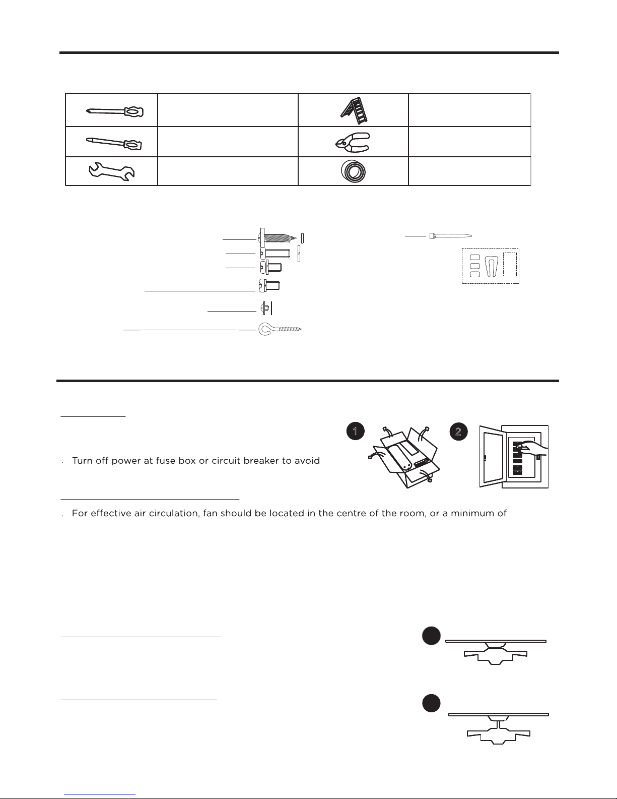
· To avoid possible electric shock, be sure electricity at the fuse box or the circuit breaker
· All wiring must be done in accordance with national and local wiring codes. Consult a
qualified electrician to ensure correct branch circuit conductor.
· Follow the recommended instructions for the proper method of wiring for the new ceiling
fan. The ceiling fan must be grounded as a precaution against possible electric shock
wiring knowledge, have the fan installed by a licensed
electrician.
· The outlet box and joist must be securely mounted and capable of reliably supporting at
least 35 lb (15.9 kg).
· Mount the lowest moving parts at least 6’ 11” (2.1 m) above floor or ground level.
· Make sure all electrical connections are sealed with proper connector and electrical tape
inside the outlet box.
· Make sure the ceiling fan is securely fastened to the ceiling.
· All set screws must be checked and re-tightened where necessary before fan operation.
WARNING!
· Mount only to an outlet box marked acceptable for fan support.
· To prevent injury, make sure the fan blades are not bent and that there are no objects
within the rotation area.
· The important precautions, safeguards and instructions appearing in this manual are not
meant to cover all possible situations. It must be understood that common sense and
caution are factors which cannot be built into the product.
· Not suitable for use with solid-state speed controls.
2

This manual is designed to make it as easy as possible for you to assemble, install, operate and maintain
the ceiling fan. The following tools listed are required for assembly and installation:
12
3
3b
3a
TOOLS REQUIRED FOR ASSEMBLY
1x star-head screwdriver
1x flat screwdriver
1x wrench
1x stepladder
1x wire stripper/pliers
1x electrical tape
After opening the package you should find all the ne cessary parts for installing this ceiling fan.
The box should also contain:
Parts Pack Containing:
2 wood screws with flat washers
2 5/32" screws with lock washers
1 3/16" screws with lock washers
1 extra blade bracket screw with
spring washer
16 blade screws with washers
1 “J” hook
1 zip tie
3 balance pieces
1 balance clip
1 instruction sheet
ASSEMBLY
Preparing for installation
Getting ready
. Unpack and inspect carefully to make sure all parts are
included and not damaged (see Fig. 1). Lay all pieces out
on a working space.
possible electrical shock (see Fig. 2).
. Choose a location where there is a high enough ceiling clearance (at least 6’ 11” (2.1 m) from the
floor to the ceiling fan’s lowest moving part).
. Ensure that the outlet box in the room’s ceiling can support the weight of the fan. Typically, if the
outlet box is marked acceptable for fan support, it can hold the fan securely.
Choosing a location for the ceiling fan
Hugger mount (for lower ceilings)
Drop-mount (for normal ceilings)
Mounting options
. This method is preferred if the ceiling is sloped or vaulted, or if ceiling
is extra high, requiring the need of a downrod (see Fig. 3b).
. Follow steps 1—9, omitting step 2 in the manual.
. This method is preferred if maximun headroom is required. The ceiling
must be completely horizontal and level (see Fig. 3a).
. Follow steps 1—9, omitting step 3 in the manual.
3
32” (81.3 cm) from adjacent walls or obstructions.

ASSEMBLY
7
5b
5a
1. Mounting bracket
Installation
Note: The mounting bracket depicted will vary
depending on the model .
. Remove the four sets of side screws from mounting
bracket and save for future use.
Wooden ceiling
. Drill two mounting holes in the ceiling joist.Securely
attach the mounting bracket to the ceiling or wooden
ceiling as indicated below (fig. 4a).
Normal masonry ceiling
. Drill two mounting holes in the ceiling joist.Securely
an outlet box marked “ Acceptable for Fan Support
”, using the supplied outlet box screws with lock
washers (see Fig. 4b).
3. Drop-mount
2. Hugger mount
Note: Canopy picture may vary depending on style
of ceiling fan.
Downrod assembly
. Loosen the two downrod set screws and remove
the clip and connection pin from the downrod
coupling. Then take away the downrod (see Fig. 5a).
. Guide motor wires through the base of the canopy
as illustracted with arrow (see Fig. 5b).
. Attach the canopy directly to top of the housing
with the coupling screws provided. Now tighten
the screws securely (see Fig. 5b).
Hands-free wiring
Canopy assembly
. Raise canopy-motor assembly to mounting bracket’s hook
and hang by the screw hole on the canopy. This will allow
for hands-free wiring (see Fig. 6).
hook, follow wiring instructions (see Fig. 6).
Hands-free wiring
. The downrod assembly has been installed into
downrod coupling upon production.
. Carefully lift the fan assembly onto the mounting
bracket.
. Rotate the fan until the notch (b) on the nylon
ball fits against the ridge (a) on the mounting
bracket (see Fig. 7).
. With the mounting bracket holding the fan assembly,
follow wiring instructions (step 4).
4
6
Mounting
bracket Flat
washer
Wood screw
4a
Outlet box screw
Lock washer
4b
NOTE: For added security, attach safety
cable from fan unit to “J” hook in outlet
box. Secure by looping zip tie through
safety cable and “J” hook. Tighten zip
tie securely.
“J” hook Zip tie

ASSEMBLY
4. Wiring instructions
Remote and Receiver Pairing
Codes are set by pushing the location of the dip switches located on the transmitter and receiver
up or down. It is important that the code used for both the remote and receiver are identical for the
two devices to be able to communicate; otherwise the remote will not be able to control the fan.
Installing Receiver Assembly
Once the connection has been made, the receiver inserts into the drop rod hanging bracket.
The canopy comes up to cover the receiver and bracket .
IMPORTANT: If you are not sure if the electrical outlet box and fan are grounded, contact a licensed
electrician for advice. They must be grounded for safe operation.
WARNING:
before wiring.
5
Between fan and receiver:
· Connect the black wire marked “L” from the fan to the black wire marked “TO MOTOR L” from the receiver.
· Connect the blue wire marked “FOR LIGHT” from the fan to the blue wire marked “FOR LIGHT” from the
receiver.
· Connect the white wire marked “N” from the fan to the WHITE wire marked “TO MOTOR N” from the receiver.
Between receiver and mains :
· Connect the black live wire marked “AC IN L” from the receiver to the live wire (typically black) from the
outlet box.
· Connect the white neutral wire marked “AC IN N” from the receiver to the neutral wire (typically white) from
the outlet box.
· Connect the green ground wires from the mounting bracket and nylon ball to the ground wire (bare or
green) from the outlet box.
If you plan to install more than one fan then each fan will require the remote and receive to
use a unique code, or else one remote will be able to control more than one fan.
Downrod
Receiver
Antenna:
DO NOT CUT
OR SPLICE

6
9
10
11
12a
12b
13
5. Attach assembly to mounting bracket
6. Blade and blade bracket
. Using the fan blade screws and washers,
attach the fan blades (see Fig. 10).
. Unhook the assembly from the mounting bracket.
. Hold the assembly by the canopy and raise up to
align the two holes in the canopy with the holes in
the mounting bracket.
. Tighten the loosened side screws and washers. Now
re-secure the screws and washers which were removed
during step 1 (see Fig. 9).
Note: This ceiling fan includes 5 dual-finished
blades. Depending on personal preference,
choose the side that best suits the décor or
furniture of your room.
7. Attach blade assembly to motor
. If there are plastic tabs shaped like bottle caps, remove
and discard them. These are stabilizers that protect the
motor during shipping.
. Remove blade bracket screws on the bottom
of the motor and use them to attach the blade
assembly to the motor. Ensure that the screws
are tightened (see Fig. 11).
8. Connect switch housing and light kit
. Install fan light (provided with package) (see Fig. 12a)
Connect wires:
The white (neutral) wire from the fan light to white (neutral)
wire from switch box with a wire nut. The black (hot) wire from
fan light to blue (hot) wire from switch box with a wire nut.
Note: If you wish to install the fan without light kit, install
the extral cap by the screws.
. Attach the fan light onto the switch box with
the switch box screw (see Fig. 12b).
9. Mounting light kit glass
. Install 2X60W candelabra-base bulbs (not included).
Install light kit glass to the light kit assembly
with rubber washer, flat washer and hex nut.
DO NOT over tighten. Install cap and screw finial
onto the light kit assembly (see Fig. 13).
ASSEMBLY
Blade Screw
Washer
Blade
Blade Bracket
Motor Screw
Blade Bracket
Plastic Insert
End Cap
Finial
Rubber Washer
Metal Washer
Hex Nut
Glass Shade
Fan Light
Switch Box
Switch Box
Screw
Fan Light
8a 8b 8c
WARNING: Be sure no bare wire or wire strands are visible after making connections. Place
green and white connections on opposite side of box from the black and blue (if applicable)
connections.
· When wires are matched up, connect them by twisting frayed ends together (see Fig. 8a).
· Screw wire connectors (3 are provided) onto the tops of the twisted wires (see Fig. 8b).
· Fasten them with electrical tape (see Fig. 8c).

7
· Restore power to ceiling fan and test for proper operation.
· The fan remote control controls the fan settings:
HI: Turn on the fan at high speed.
MED: Turn on the fan at medium speed.
LOW: Turn on the fan at low speed.
LIGHT: ON/OFF: Press and release immediately to turn
DIMMER: Press and hold on to dim or brighten
lights to the desired level and release
(only for the tungsten bulb).
Forward and reverse direction function.
This ceiling fan is equipped with a reverse switch
for downward or upward air-flow.
14
15
OPERATION
Note: Do not use the reverse switch when the fan blades are in motion.
Forward function
· On this setting, the fan will turn counter-clockwise
warmer weather to circulate hot air away from
your living space (see Fig. 14).
Reverse function
. On this setting, the fan will turn clockwise. Use this
function during cooler weather to re-circulate warm
air (see Fig. 15).
LIGHT
ON/OFF
HI
MED
DIMMER
FAN OFF
LOW
Reverse
Forward
Switch housing
Reverse switch
9V
Battery
Install the 9 V battery (included). To prevent damage to transmitter
remove the battery if not used for long periods .
IMPORTANT NOTE:
bulbs with over 190 w, your light will automatically turn o, Ensure bulb wattage is
always below 190 W!
Your fan has an energy-saving wattage limiter. If you replace the
ASSEMBLY

8
MAINTENANCE
. Because of the fan’s natural movement, some connections may become loose. Check the support
connections, brackets and blade attachments twice a year. Make sure they are secure.
. There is no need to oil your fan. The motor has permanently-lubricated bearings.
CARE AND CLEANING
. Dust your fan periodically with a soft, dry cloth. Do not use harsh cleaners or materials as they may
damage the unit.
. To prevent bending the blades during cleaning, support the blades so that no pressure is applied to
them.
Caution!
Do not allow water to come in contact with fan blades or the ceiling fan. Doing so will create
fire and/or shock hazards, damaging property.
TROUBLESHOOTING
If problems persist, seek help from a certified electrician.
Problem
Fan is noisy
during
operation
Fan does not
start
Possible reason
. Blade screws are loose.
. The mounting bracket or canopy is loose.
. Screws securing decorative housing to
hanger are loose.
. Lamp shades or bulbs are loose.
. Screws securing downrod to hanger are
loose.
. Wire connectors are vibrating against the
inside of canopy.
. Light kit or light bulb is not firmly
attached.
. Canopy is rattling against ceiling.
. Motor housing screws have come loose.
. Fuse or circuit breaker is blown.
. Loose or incorrect power line
connections to the fan or switch wires.
Solution
. Tighten screws on blades with a
screwdriver.
. Check and fasten the screws.
. Tighten by hand, as necessary.
. Check and fasten screws.
. Disconnect power at fuse box, loosen
canopy and re-position connectors.
. Remove and re-attach.
. Be sure canopy is not touching ceiling.
. Check and fasten the screws.
. Check main fuse and branch circuit
fuses or circuit breaker. Repair as
necessary.
. Check all the wire connections to
fan and housing wiring. Repair as
necessary.
Caution! Make sure the main

9
16
TROUBLESHOOTING
Light does
not work
Fan does
not seem to
move much
air
Fan wobbles
or shakes
excessively
· Wires are not properly connected.
· Light bulbs are faulty.
· This fan is equipped with a 190 W
LIMITER that will automatically turn
the light o total wattage exceeds
the maximum wattage level.
· Fan is in reverse (blades are moving in
clockwise direction).
· Fan is not properly located.
· Screws securing fan blade clips to motor
are loose.
· Fan blade and its blade clip are not
fastened securely.
· Canopy and mounting bracket are not
tightened securely.
· Blades are unbalanced.
Touching
ceiling
· Ensure wire connector in switch
housing is connected.
· Unscrew light bulbs and discard
properly.
· Turn the power OFF and replace
the bulbs with lower wattage bulbs
so that the total wattage is below
190 W.
· Counter-clockwise (forward) is
recommended in warm weather.
rotation to stop. Use the eraser end
of a pencil to change the forward/
reverse slide switch.
· Place fan in the centre of the room
so there is at least 12" (30 cm)
between the end of the blades and
walls or other obstructions.
. Make sure that screws which attach
fan blade clips to motor are fastened
and tightened.
. Tighten screws of fan blade to blade
clip securely.
. Ensure that canopy and mounting
bracket are tightened securely to
ceiling joist.
. Check by selecting a point on the
ceiling above the tip of one of the
blades. Measure this distance and
ensure all blades are even (see Fig.
16). If all blade levels are not equal,
adjust accordingly (see Balancing Kit
Manual).
ENVIRONMENTAL PROTECTION
Discarded electrical appliances are recyclable and should not be discarded in your regular
domestic waste! Please actively support us in conserving resources and protecting the
environment by returning this appliance to a collection centre (if available).
Battery reclamation (please keep to comply with the local law).
Problem Possible reason Solution

10
WARRANTY
This Likewise product carries a one (1) year warranty against defects in workmanship and materials.
Trileaf Distribution agrees to replace the defective product free of charge within the stated warranty period,
when returned by the original purchaser with proof of purchase. This product is not guaranteed against wear
or breakage due to misuse and/or abuse.
Subject to the conditions and limitations described below, this product, if returned to us with proof of
purchase within the stated warranty period and if covered under this warranty, will be repaired or
replaced (with the same model, or one of equal value or specification), at our option. We will bear the
cost of any repair or replacement and any costs of labour relating thereto.
These warranties are subject to the following conditions and limitations:
a) A bill of sale verifying the purchase and purchase date must be provided;
b) This warranty will not apply to any product or part thereof which is worn or broken or which has
become inoperative due to abuse, misuse, accidental damage, neglect or lack of proper installation,
operation or maintenance (as outlined in the applicable owner’s manual or operating instructions)
or which is being used for industrial, professional, commercial or rental purposes;
c) This warranty will not apply to normal wear and tear or to expendable parts or accessories that
may be supplied with the product that are expected to become inoperative or unusable after a
reasonable period of use;
d) This warranty will not apply to routine maintenance and consumable items such as, but not limited
to, fuel, lubricants, vacuum bags, blades, belts, sandpaper, bits, fluids, tune-ups or adjustments;
e) This warranty will not apply where damage is caused by repairs made or attempted by others
(i.e. persons not authorized by the manufacturer);
f) This warranty will not apply to any product that was sold to the original purchaser as a
reconditioned or refurbished product (unless otherwise specified in writing);
g) This warranty will not apply to any product or part thereof if any part from another manufacturer
is installed therein or any repairs or alterations have been made or attempted by unauthorized
persons;
h) This warranty will not apply to normal deterioration of the exterior finish, such as, but not limited
to, scratches, dents, paint chips, or to any corrosion or discolouring by heat, abrasive and chemical
cleaners; and
i) This warranty will not apply to component parts sold by and identified as the product of another
company, which shall be covered under the product manufacturer’s warranty, if any.
Additional Limitations
This warranty applies only to the original purchaser and may not be transferred. Neither the retailer nor
the manufacturer shall be liable for any other expense, loss or damage, including, without limitation,
any indirect, incidental, consequential or exemplary damages arising in connection with the sale, use or
inability to use this product.
Notice to Consumer
This warranty gives you specific legal rights, and you may have other rights, which may vary from
province to province. The provisions contained in this warranty are not intended to limit, modify, take
away from, disclaim or exclude any statutory warranties set forth in any applicable provincial or
federal legislation.
Imported by
Trileaf Distribution Trifeuil Toronto, Canada M4S 2B8
Made in China
Table of contents
Other Likewise Fan manuals