LIKUID L07 User manual

MANUAL
HOUSINGS
Likuid L07-L19-L37-L61-L91

Fecha | Date: 09/09/2013
Código Doc. | Document N: M-Housings-R04
MANUAL
HOUSINGS
Likuid L07-L19-L37-L61-L91

MANUAL
M-Housings -R04
Page 3 of 8
1. INTRODUCTION
This user manual describes he echnical charac eris ics and he ins ruc ions for opera ion, main enance, assembling and
disassembling of Likuid housings. Wi h he aim of guaran eeing an op imum performance, i is s rongly recommended o follow
scrupulously he following indica ions.
The design of he housings has been valida ed under he corresponding quali y con rol pro ocols, so ha he op imum performance
is guaran eed in accordance o echnical specifica ions.
When he produc is received and/or unpacked:
•Ask for assis ance of qualified echnicians for ensuring ha he ins alla ion is made correc ly.
•Please inform Likuid immedia ely of any ex ernal damage or defec in he packing or in he produc i self.
•Follow scrupulously he drawings supplied for housings assembling/disassembling.
2. T CHNICAL SP CIFICATIONS
The main charac eris ics of Likuid’s housings are he following:
Ma erial
S ainless s eel
(diverse range)
Morph
olog
y
Tubular
Range of pH resis ance
0
-
14
Maximum pressure
1
10 bar
Range of empera ure
1
5
-
95
ºC
Fluid
2
Group
2
S andard models
L7, L19, L37, L61, L9
1
1
According to 97/23/CE Directive, in applicable technical requirements of Article 3 Section 3
2
For fluids from the Group II, according to 97/23/CE Directive, in applicable technical requirements of Article 3 Section 3
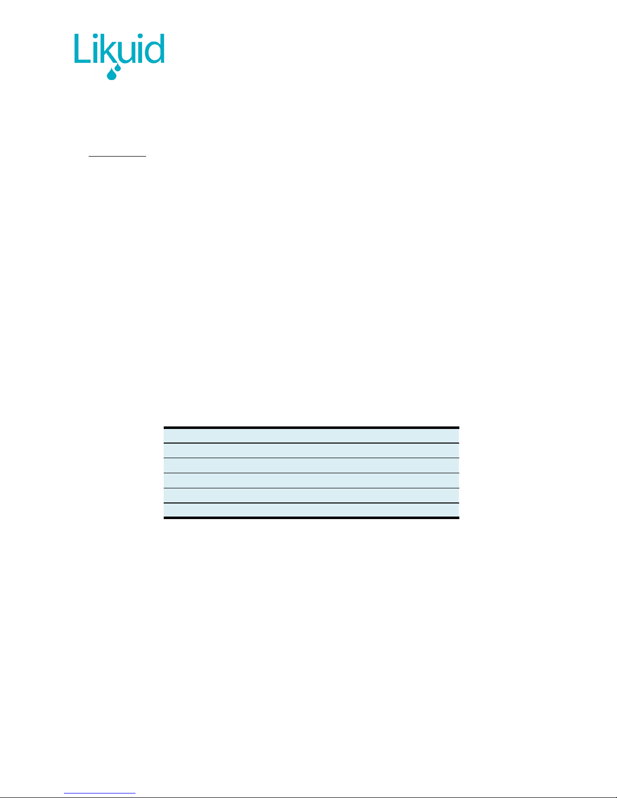
L07 L19 L37 L61 L91
A1195mm 1195mm 1195mm 1195mm 1195mm
B880mm 880mm 880mm 880mm 880mm
CDN100 DN150 DN200 DN300 DN350
DØ53mm Ø77mm Ø96mm Ø110mm Ø128mm
Q7 membranes 19 membranes 37 membranes 61 membranes 91 membranes
M23kg 46kg 73kg 138kg 186kg

MANUAL
M-Housings -R04
Page 4 of 8
3. LIST OF COMPON NTS
The s andard supply consis s on he following componen s:
•
1 Housing
•
Assembling supplemen s (Double screws – M5 y M6 + Washers M5 + Nu s M5)
•
2 back-pla es (wi h and wi hou hole-reduc ions)
•
2 fla gaske s for housing/pipes connec ion
•
2 O-rings for permea e pipes connec ion
•
O-rings for membranes (quan i y depends on model)
•
Moun ing screws M6 (quan i y depends on model)
•
Ceramic membranes (quan i y depends on model)
The uni is delivered as a comple e assembled se (wi h he excep ion of 2 fla gaske s and assembling supplemen s).
There is a possibili y o include accessories for permea e:
•DIN2576 flange
•Ready o weld
•Clamp
•Blind
O hers, consul Likuid.
The dimensions of he permea e connec ions for each housing model are included in he able below:
Hydraulic diam. Threads posi ion Screws
L07 DN12 DN06 M6
L19 DN20 DN10 M8
L37 DN32 DN20 M10
L61 DN40 DN25 M12
L91 DN50 DN32 M14

MANUAL
M-Housings -R04
Page 5 of 8
4. ASS MBLING INSTRUCTIONS
4.1. ASS MBLING OF MODUL S:
The sequence for he assembling of modules is described below:
ST P D SCRIPTION GRAFICAL SCH M
1
Screw in comple ely he assembling supplemen s,
by he M6 end, in he upper pla e of he module.
Upper plate of the module: with the module in
vertical position, upper part with respect to the
identification label
(Orange pieces)
2
Ins all he back-pla e which has he hole-
reduc ions, urned over 180º respec ing i s
permanen posi ion. I mus have he hole-
reduc ions nex o he pla e, fully in con ac wi h
he assembling supplemen s.
(Pink piece)
3
Fix he assembling supplemen s wi h he
corresponding M5 washers and nu s.
(Yellow pieces)
4
In horizon al posi ion of he module, inser
carefully he ceramic membranes by he opposi e
side, un il reaching he s op in he back-pla e
previously ins alled. Membranes mus be inser ed
from he bo om o he op.

MANUAL
M-Housings -R04
Page 6 of 8
ST P D SCRIPTION GRAFICAL SCH M
5
Af er ins alling he membranes, pu he second
back-pla e (wi hou hole-reduc ions). Use he O-
rings and moun ing screws M6.Torque approx.
10 Nm. Membranes mus pro rude approx. 4 mm
from he pla e.
The screws mus be igh ened crosswise. Since
his opera ion allows he O-rings o be igh ened
and provides he wa er- igh ness of he module, i
mus be done carefully and uniformly.
NOTE: only one membrane is represented in the
picture.
6
Release he ini ially ins alled back-pla e (wi h
hole-reduc ions), urn i over 180º and repea he
ins ruc ion 5. Membranes are now moun ed in he
housing.
4.2. ASS MBLING OF MODUL S:
•
Af er unscrewing he screws in he back-pla e of bo h sides, back-pla es mus be ex rac ed carefully. Some imes, back-pla e
can be s uck o he pla e due o he high opera ing pressure. For hese cases, he back-pla es have some M5 hreaded holes
(marked wi h arrows in he pic ure below) where screws can be inser ed and used as ex rac ors, so ha when hey are
igh ened, pressure is applied on he pla e and he back-pla e is ex rac ed from he housing.
•Af er removing he back-pla es from bo h sides, remove he O-rings from one side carefully (Don’ use Sharp ools).
•Remove he membranes from he side where he O-rings are s ill presen . Be careful: membranes are jus hold a he ips of
he module.

MANUAL
M-Housings -R04
Page 7 of 8
4.3. OTH RS
I is recommended NOT o reuse he O-rings.
If subs an ial vibra ions are hough o occur, i is recommended o use fixing glue for screws.
Tools for manipula ion/eleva ion of housings mus be available for manipula ing heavy modules.
5. WARRANTY
Unless here is an explici con rac ual specifica ion ha modifies he general warran y condi ions, Likuid modules are guaran eed
agains all manufac uring or assembling faul s for a period of 12 mon hs from he s ar ing-up, or 15 mon hs from he da e of
purchase.

MANUAL
M-Housings -R04
Page 8 of 8
This manual suits for next models
4
Table of contents
Popular Camera Accessories manuals by other brands

Swisson
Swisson XMT-120A user manual

Tempo Communications
Tempo Communications 508S manual

Rollei
Rollei Lion Rock MH-7 Mark II user manual

EnerSys
EnerSys DataSafe XE Series Installation, operation and maintenance manual

Videotec
Videotec MNVCAVTPSC 0604 operating instructions

Sachtler
Sachtler DV 10 SB manual