Limousin 134 10 12 User manual

Description of the appliance
Installation instructions
Operating instructions
Spare parts
Warranty certificate
Document n° 1054-9 ~ 20/06/2007
STAUB FONDERIE
SARL with the capital of 6 359 540
Head Office Address
2, rue Saint Gilles
68230 TURCKHEIM
RCS Colmar
SIREN 444 881 953
Address
Administration and manufacturing
BP 73
59660 MERVILLE (FRANCE)
Telephone : 00 333 28 43 43 00
Fax : 00 333 28 43 43 99
Subject to modifications.
LIMOUSIN
Multifuel stove
Model : 134 10 12
Output : 10 kW
DIN EN 13240 : 2005-10 Technical manual
to be saved
by the user
for future reference

2 Technical manual “1054”
Limousin ~ Mod 134 10 12
CONTENTS
Product information. . . . . . . . . . . . . . . . . . . . . . . . . . . . . . . . . . . . . p. 3
Package . . . . . . . . . . . . . . . . . p. 3
Optional. . . . . . . . . . . . . . . . . . p. 3
General characteristics . . . . . . . . . p. 3
Description . . . . . . . . . . . . . . . . p. 3
Principle of operation . . . . . . . . . . p. 3
Installation instructions . . . . . . . . . . . . . . . . . . . . . . . . . . . . . . . . . . p. 4
Warning to the user . . . . . . . . . . . p. 4
Location of the unit . . . . . . . . . . . p. 4
Chimney . . . . . . . . . . . . . . . . . p. 4
Mounting the flue collar . . . . . . . . . p. 5
Connection to flue . . . . . . . . . . . . p. 5
Mounting the tray . . . . . . . . . . . . p. 6
Pre-utilisation check . . . . . . . . . . . p. 6
Chimney maintenance and sweeping . p. 7
Instructions for user . . . . . . . . . . . . . . . . . . . . . . . . . . . . . . . . . . . . p. 8
Fuel . . . . . . . . . . . . . . . . . . . . p. 8
Instruction for use with wood . . . . . . p. 9
Instructions for use with smokeless fuel p. 9
Cleaning . . . . . . . . . . . . . . . . . p. 9
Maintenance of the Chimney . . . . . . p. 9
Maintenance of the stove body . . . . . p. 9
Recommendations . . . . . . . . . . . . p. 9
Trouble Shooting . . . . . . . . . . . . p. 10
Spare parts . . . . . . . . . . . . . . . . . . . . . . . . . . . . . . . . . . . . . . . . . p. 11
FRANCO BELGE congratulates you on your choice.
FRANCO BELGE, guarantees the quality of its appliances and is committed to meet its
customers’ needs.
FRANCO BELGE, which can boast a 80-year experience in the industry of heating devices, uses
state-of-the-art technologies
to design and manufacture its whole range of products.
This document contains instructions on how to install your appliance and make full use of its
functions, both for your comfort and safety.
This appliance is meant to burn wood safely
WARNING
Incorrectly installed, this appliance can be dangerous and possibly cause serious accidents.
We recommend that you engage the services of a professional engineer for its installation
and the regular maintenance requirements

1. Product information
1.1. Package
•1 package : Stove complete.
1.2. Optional
•Boiler
1.3. General characteristics
FUEL : WOOD
Reference . . . . . . . . . . . . . . . . 134 10 12
Nominal output . . . . . . . . . . . . kW 10
. . . . . . . . . . . . . . . . . . . Btu/hr 34 000
Chimney draft required . . . . . . . . Pa 11
Usable firebox dimensions
- width . . . . . . . . . . . . . . . . mm 540
- depth . . . . . . . . . . . . . . . . mm 250
- height . . . . . . . . . . . . . . . . mm 200
Log dimensions
- Length maxi . . . . . . . . . . . . . cm 50
Ash pan capacity . . . . . . . . . . litres 6,8
Net weight . . . . . . . . . . . . . . . kg 160
Volume heated . . . . . . . . . . . . m3380
Wood
- Fuel rate . . . . . . . . . . . . . . kg/h 3,3
- Maximum flue gas temperature. . . °C 291
- Efficiency . . . . . . . . . . . . . . . % 71,9
- Co (13% O2) . . . . . . . . . . . . . % 0,28
FUEL : ANTHRACITE (smokeless fuel)
Tested with fuel brand name “phurnacite” entering in
category A, table B2 frpm the standard EN 13240.
- Nominal heat output . . . . . . . . kW 10
- Chimney draft required . . . . . . . Pa 12
- Flue gas temperature . . . . . . . . °C 234
- Fuel rate . . . . . . . . . . . . . . kg/h 1,7
- Efficiency . . . . . . . . . . . . . . . % 67
- Co (13% O2) . . . . . . . . . . . . . % 0,24
1.4. Description
Stove, in conformity with DIN EN 13240 : 2005-10
•Intermittent-burning heating appliance.
•Detachable flue collar for rear or top chimney
connection.
•Detachable top for easy handling and cleaning (rear
flue outlet only).
•Adjustable air control for controlling the burning rate.
•Air control for lighting.
•Large ash-pan.
•Side loading door.
1.5. Principle of operation
The “ Limousin ” is designed for operation with the doors
closed.
Heat is mainly diffused by radiation, through the window
and body of the appliance.
Combustion occurs on the grate, with draught entry
through the top of the combustion chamber when using
wood and under the grate when using smokeless fuel.
Limousin ~ Mod 134 10 12 Product information
Technical manual “1054” 3
1 9 8
4 5 5
5 7 5
7 4 1
6 6 0
4 5 9
Ø 1 5 3
Figure 1 - Dimensions in mm

2. Installation instructions
2.1. Warning to the user
All the local and national regulations, and in
particular those relating to national and European
standards, must be observed when installing the
appliance.
An incorrectly installed heating appliance can
cause serious accidents (chimney fires, burning of
plastic insulation materials, in partition walls, etc.).
The insulation of both the appliance and the
exhaust gas pipe has to be reinforced and done
acc o r d i n g t o t h e Stand a r d s a n d t h e B u ildin g
Regulations for safety reasons.
Failure to respect the mounting instructions leads to
engage the responsibility of the one doing the
installation.
The manufacturer’s responsibility shall be limited to the
supply of the equipment.
2.2. Location of the unit
Ventilation : For satisfactory appliance operation with a
natural draught, check that sufficient air for combustion
is available in the room.
Position of the unit : For new installations, select a
central position within the house, to provide a good heat
distribution around the building. The heat distribution
towards the other rooms will be made through the
communicating doors.
These rooms must be in negative pressure or must
include ventilation gratings.
Floor and walls : Make sure they are not combustible
or covered with combustible material (as per the
Building regulations).
O t h e r w i s e i t m u s t n e c e s s a r y t o i n s t a l l a
non-combustible protection.
There must be a clearance of at least 150 mm at each
side of the appliance and at the back of the appliance
from a non-combustible wall.
This distance must be extended to a minimum
clearance of 350 mm from any combustible materials.
This measurement may be reduced to a minimum gap
of 50 mm when the non-combustible wall is at least
200 mm thick.
When using a single wall
flue pipe, there must be a
clearance (A) of at least
three times its diameter
(B) from any combustible
materials.
If the appliance has to be
located in an opening, this
d i s t a n c e m u s t b e
extended to a minimum
clearance (A) of 375 mm
from the pipe or the stove
body to any combustible
materials.
Hearth :
-T h e a p p l i a n c e m u s t
sta n d o n a f i r e proof
hearth.
-It is possible to provide a hearth made of non
combusible board/sheet material or tiles at least 12
mm thick.
-Constructional hearths should be constructed of solid
non combustible material at least 125 mm thick
(including the thickness of any non combustible floor
under the hearth).
-The hearth must protrude at least 225 mm in front of
the stove and 150 mm each side.
-If the hearth is constructed on timber, there must be a
clearance of at least 250 mm from the timber to the top
surface of the hearth.
-See section J of the Building regulations.
2.3. Chimney
The chimney must comply with Current Building
Regulations. If in doubt, consult your Dealer or local
Building Inspector.
Existing flue :
-The flue must be suitable for the installation of fuel
burning appliances, otherwise it must necessary to
install a tubing.
-The flue must be in good condition and must provide
sufficient draught. (refer to technical details p. 3).
-The flue must be clean. It should be swept to remove
soot and dislodge tar deposits.
-The flue must be well insulated. If the flue inner wall
surfaces are cold, a good thermal draw is impossible
causing condensation problems (tar formation etc) to
occur.
-The flue must be watertight.
-The chimney must have a constant cross section.
-The flue must not be shared with any other appliance.
-The chimney must be at least 4.5 m (15 ft high).
-In case of a flat roof or when the roof gradient is lower
than 15°, the stack must be 1,2 m (4 feet) high at least.
-The capping must not restrain the draught.
-If the chimney has any downdraught tendency, due to
its position in relation to nearby obstacles, an
anti-downdraught cowl must be installed on the
chimney or the chimney height must be increased.
4 Technical manual “1054”
Limousin ~ Mod 134 10 12 Installation instructions
1 5 0
1 5 0 3 0 0
1 5 0
B
A
A
C
4 0 0
Figure 2 - Clearances

-If the chimney draught is excessive or irregular, a
draught stabiliser (barometric damper) must be
installed to the connector pipe.
Chimney to be built / New flue
-The chimney must comply with Current Building
Regulations. If in doubt, consult your Dealer or local
Building Inspector.
-The appliance must not support the weight of the flue.
-Consult a chimney specialist for advice on suitable
flue systems for solid fuel appliances.
-It must be distant from any combustible material
(walls, cross members)
-It must permit an easy sweeping.
2.4. Mounting the flue collar
The stove is supplied with a connection flue collar with
an inner diameter of 153 mm.
2.4.1. Flue outlet at rear
Figure 3
-Remove the rear heat shield 5.
-Remove the top plate (2 screws).
-Remove the flue baffle.
-Fit the sealing rope 2 in the groove at rear and fix the
flue collar 1 with 3 bolts and washers supplied.
-Replace the flue baffle.
-Replace the top plate.
-Remove the cut-out in the rear heat shield and refit.
2.4.2. Flue outlet on the top
Figure 4
-Remove the top plate (2 screws).
-Remove the flue baffle.
-Remove the blanking plate 3 and the clamp 5 and refit
them at the rear, ensuring there is a good seal.
-Fix the flue collar 1 on the top with 3 bolts and washers
supplied, ensuring there is a good seal.
-Replace the flue baffle.
-Replace the top plate.
In this case, the cut-out of the heat shield must not be
remove.
2.5. Connection to flue
-The stove must be installed as close as possible to the
chimney.
-The stove should be connected to the flue by a smoke
pipe, approved for installation with combustion
products (e.g. 316 grade 1 mm thick stainless steel or
vitreous enamelled steel).
Limousin ~ Mod 134 10 12 Installation instructions
Technical manual “1054” 5
7
4
1
2
3
6
Figure 3 - Rear flue outlet
1
2
3
4
5
2
7
Figure 4 - Smoke exit from top
1- Flue collar
2- Ceramic rope
3- Blanking plate
4- Clamp
5- Screw 6 x 25
6- Screw 6 x 20
7- Rear heat shield

-Pipe diameter must not be less than the appliance
spigot diameter.
-If there is no other solution, the reduction can not be
more than one diameter lower than the flue spigot and
be situated as distant as possible from the flue
connection of the appliance.
-The connection can be either vertical or horizontal. For
horizontal connections, avoid right angle bends.
-The join between the connection pipe and the
stovepipe, and the flue, must be leak tight.
-For the premises equipped with a mechanical
controlled ventilation, the airtightness has to prevent
the exhauster drawing out the smokes from the
exhaust gas pipe.
-The connection pipe and any draught stabiliser must
have access for cleaning.
2.6. Mounting the tray
Figure 6
To avoid damage during transport, the tray has been
stored behind the main door.
-Fix the tray on the appliance.
-Centre on tab “A” and lower into place.
2.7. Pre-utilisation check
-Check that the glass is not damaged.
-Check that the smoke passages are not obstructed by
packaging or removable parts.
-Check that the seals of the smoke-line are in good
condition.
-Check that the doors close correctly.
-Check that all removable parts are correctly installed.
(side walls, flue baffle, grates, etc.)
Note : if it acts of a ceramics braid, it is consumable and
thus brought to be changed by the user
6 Technical manual “1054”
Limousin ~ Mod 134 10 12 Installation instructions
1
2
3
4
11
3
6
4
5
Figure 5 - Chimney
connections
A
Figure 6 - Mounting the tray
1- Chimney
2- F u n n e l - s h a p e
fireproof material
3- Non combustible
register plate
4- Cleaning access
door
5- Liner

2.8. Chimney maintenance and sweeping
Very important : To avoid accidents (chimney fire,
etc.), regular maintenance should be carried out. If the
stove is regularly used, the chimney should be swept
several times per year, together with the stovepipe
connection section.
First remove the two retainer grates (# 1, fig. 7), then
remove the side walls (# 2 & 3, fig. 7) and remove the
flue baffle (# 4, fig. 7).
Refit the parts in the reverse order (fig. 8).
If the chimney catches fire, you must cut off the flue
draught, close the doors and windows, hatches and
keys, remove the embers from the stove, stop up
the connection hole with wet cloths and call the Fire
Brigade.
DO NOT OPEN THE DOOR OF THE APPLIANCE
(OR AIR INLET) UNDER ANY CIRCUMSTANCES.
Chimney condition should be checked at least once
per year by a professional engineer.
Limousin ~ Mod 134 10 12 Installation instructions
Technical manual “1054” 7
1
2
34
Figure 7 Removing the flue baffle
1- Fuel retainer
2- Wall
3- Back wall
4- Flue baffle
4
2
3
1
Figure 8 Put back into position the elements
1- Flue baffle
2- Back wall
3- Wall
4- Fuel retainer

3. Instructions for user
The manufacturer will not be responsible for damages
on parts of the appliance due to the use of prohibited
fuel or due to an alteration of the appliance or its
installation. Only use replacement parts supplied
by the manufacturer.
Don’t run the stove in mild weather with smokeless
fuels : Under certain circumstances (e.g. fog and
r e p e a t e d t h a w ) t h e c h i m n e y w i l l n o t d r a w
sufficiently well and thus be at the origin of
asphyxia. Awaiting better weather circumstances,
don’t use any smokeless fuels but only wood.
At the first lighting, the fire must be progressively
increased to allow the various parts to expand normally
and to dry up.
Note : When the fire is lit for the first time, the stove may
give off fumes from the new paint. This is normal but
ensure the room is well ventilated during the first few
hours of operation.
Warning : properly installed and operated this
appliance will not emit fumes into the dwelling.
Occasional fumes from de-ashing and re-fuelling may
occur. Persistent fume emission is dangerous and must
not be tolerated. If fume emission does persist :
-Open doors and windows to ventilate room.
-Let the fire out and dispose of fuel from the appliance.
-Check for flue or chimney blockage, and clean if
required.
-Do not attempt to relight the fire until the cause of the
fume emission has been identified and corrected. If
necessary seek expert advice.
Note : It is recommended to use a fireguard in the
presence of children, and also in the presence of old
and/or infirm people.
3.1. Fuel
This appliance is not an incinerator.
Use hard wood logs, which have been cut for at least
two years and stored, under a ventilated shelter.
Use hardwood that have a higher calorific value per cu
metre (Yoke-elm, oak, ash, maple, birch, elm, beech,
etc.). Large logs must be split and cut to an useful
length, before being stored in a sheltered and ventilated
place.
•Recommended fuel :
The best fuels for use with the Franco Belge “Belfort”
are :
Seasoned wood. - hard wood logs that have been cut,
split and stored for at least two years with a minimum
moisture content of 20 % e.g. oak, beech, elm etc.
Anthracite – dry steam coal fuels as described in type A
– table B2 of the Standard – smokeless fuels along with
coalite and anthracite.
•Prohibited fuel :
A n y f o r m o f
housecoal
(bituminous coal) or
petroleum based
fuels.
W e d o n o t
r e c o m m e n d t h a t
unseas oned wo od
(green wood) is used
due to it’s high levels
of moisture which will
produce tar and in
turn can cause the
insides of the stove
and the lining of the
chimney to become
coated which in turn
c o u l d l e a d t o a
chimney fire.
W e d o n o t
r e c o m m e n d
recovered wood e.g
r a i l w a y
sleepers,chipboard,
pallets are burned as
t h e s e h a v e b e e n
t r e a t e d a n d w i l l
product a great deal
of pollution to the
environment and will
o v e r h e a t t h e
appliance.
8 Technical manual “1054”
Limousin ~ Mod 134 10 12 Instructions for user
A
B
B 1 B 2
C
C 1 C 2 C 3
E
F
H
G
Figure 9 - Operating devices
A : Door lock
B : Draught control secondary air
when burning wood :
B1 = flap opened
B2 = flap closed (keep close when
burning solid fuel).
C : Draught control primary air when
burning solid fuel
C1 = wheel opened
C2 = wheel closed (keep close
when burning wood).
C3 = de-ashing access
E : tool
F: Poker
G: Ash
tray
H: Loading
door lock

3.2. Instruction for use with wood
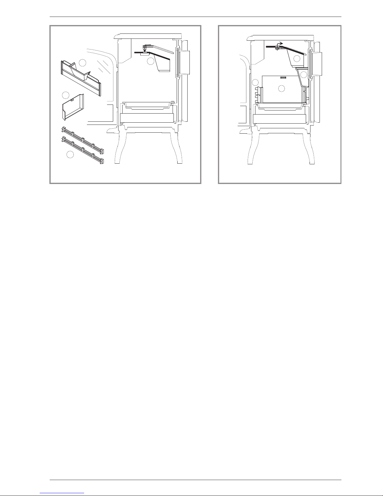
3.2.1. Lighting (figure 9)
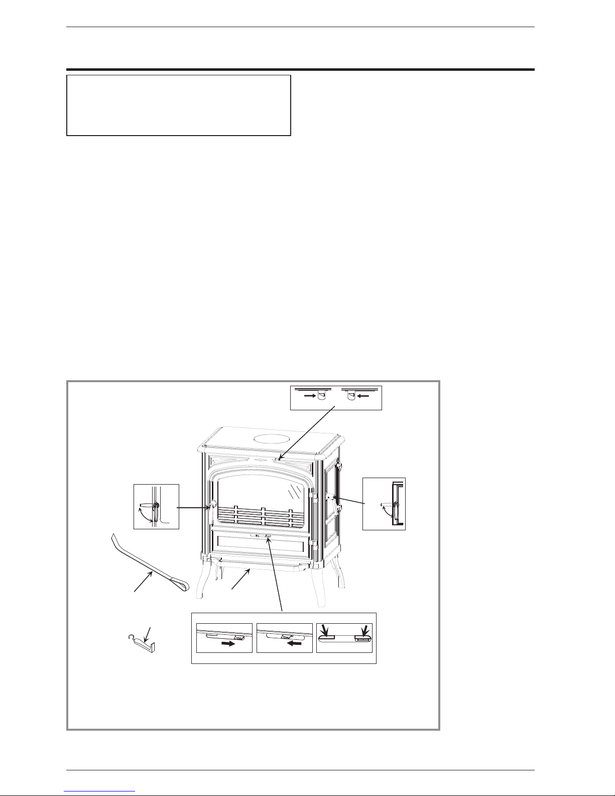
-Slide the top air control (# B1) and the lower air control
(# C1) to the right.
-Open the front door and lay firelighters or rolled up
newspapers on the grate with a reasonable quantity, if
necessary, of dry kindling wood. Place 2 or 3 small
logs on top.
-Light the newspaper or firelighters using a long taper
and close the front door.
When the fire is burning fiercely, add further logs of a
diameter up to 10 cms.
When the stove body is very hot, close the lower air
control (# C2).
The burning rate can now be adjusted by moving the top
air control to the left (# B1). Experience will show you
which settings are best for your situation.
3.2.2. Re-fuelling
It is advisable to wait for the fire to be reduced to hot
embers before re-loading. The door should also be
opened slowly when re-loading.
3.3. Instructions for use with smokeless
fuel
3.3.1. Lighting
•Close the top air control by sliding it to the left (# B2).
•Open the lower air control by sliding it to the right
(# C1).
•Open the front door and lay firelighters or rolled up
newspapers on the grate with a reasonable quantity, if
necessary, of dry kindling wood. Place a small quantity
of solid fuel on top.
•Light the newspaper or firelighters using a long taper
and close the door.
•When the fire is burning fiercely, add further fuel.
•When the stove body is hot, adjust the burning rate
with the lower air control (# C).
3.3.2. Re-fuelling
-Open the lower air control (# C1).
-Open the front door and add fuel.
-Leave the lower air control open for a few minutes to
allow the initial volatiles in the fuel to burn.
-Adjust the lower air control to the desired position
(# C).
3.4. Cleaning
It is essential to keep the grate free from a heavy build
up of ashes.
R E M E M B E R T O B U R N S M O K E L E S S F U E L
CORRECTLY, AlR SHOULD BE ALLOWED TO FLOW
FROM THE ASH PIT AREA THROUGH THE GRATE
AND THROUGH THE FUEL. IF THE GRATE OR ASH
PAN ARE CONGESTED, THE PERFOMANCE WILL
BE EFFECTED.
If burning smokeless fuel always empty the ash pan at
least once a day or whenever it is full of ashes. Never
allow the ashpan to overfill allowing ash to be in contact
with the underside of the grate. If this condition is
allowed, the grate will wear out pre-maturely.
3.5. Maintenance of the Chimney
Very important : In order to avoid any incident
(chimney fire, etc...), maintenance tasks must be
carried out regularly.
If the appliance is regularly used, the chimney
should be swept several times per year, together
with the stovepipe connection section. If the
chimney catches fire, you must cut off the flue
draught, close the doors and windows, hatches and
keys, remove the embers from the stove, stop up
the connection hole with wet cloths and call the Fire
Brigade.
Chimney condition should be checked at least once per
year by a professional engineer.
3.6. Maintenance of the stove body
•The stove must be regularly cleaned.
•Remove all deposits from the combustion chamber
and clean the grate area.
•The vitro ceramic glass can only be cleaned using a
soft cloth and stove glass cleaner, available from your
Franco Belge Dealer. DO NOT USE ABRASIVES
•The vitro ceramic glass resists a temperature of 750°C.
If the glass should be broken, it is recommended that
only an original factory replacement should be fitted.
•Check that there are no obstructions before relighting
after a long period of disuse.
•The appliance must not be used with a flue serving
several appliances.
•To maintain the grates ventilation free of any
obstruction,
For enamelled finishes, the stove body can be cleaned
using a soft cloth either dry, or slightly damp with a very
mild detergent.
NEVER CLEAN ENAMEL SURFACES WHILST THE
STOVE IS HOT.
The cast iron body panels of non-enamelled stoves can
be cleaned with a proprietary stove cleaner or
re-sprayed / touched up using a stove paint. These
products are available from your Franco Belge Dealer.
3.7. Recommendations
This appliance produces heat and may cause severe
burns if touched. The stove may still be hot even
when the fire has burnt out.
KEEP CHILDREN AWAY.
Limousin ~ Mod 134 10 12 Instructions for user
Technical manual “1054” 9

3.8. Trouble Shooting
Problem Probable causes -Action
Fire difficult to start
Fire goes out
Wood green, too damp or poor
quality.
-Use the recommended fuel.
Logs are too big. -To light the fire, use small, very dry twigs. To maintain
the fire, use split logs.
Air starvation. -Open lower air control (coal) or top air control (wood).
Insufficient draught. þ-Check that the flue is not obstructed, sweep it if
necessary
-Seek advice from a chimney specialist.
Fire burns too quickly. Too much draught. -Ensure that the lower air control is closed (with wood
burning)
-Partially close the top air control lever.
Excessive draught. þ-Install a draught stabiliser. Consult your Dealer.
Poor quality wood. -Do not continuously burn small wood, sticks, bundles,
carpentry offcuts (plywood, pallets), etc.
Smokes when lighting up. Flue duct is cold. -Burn paper and kindling wood to increase heat.
Room is in decompression. -In houses equipped with mechanical ventilation, partly
open a window until the fire is well established.
Smokes while burning. Draught is insufficient. þ-Consult a chimney specialist.
-Check that the flue is not obstructed, sweep if
necessary.
Down draught. þ-Install an anti-down draught cowl. Consult your Dealer.
Room is in decompression. þ-In houses equipped with Mechanical Ventilation, an
outside air intake must be installed for the chimney.
Low heat output. Incorrect Fuels. -Use the recommended fuel.
10 Technical manual “1054”
Limousin ~ Mod 134 10 12 Instructions for user
Instructions for user
þ: This sign means that you should asked
for a qualified engineer to do the work.

4. Spare parts
When ordering spare parts, specify the stove type and serial number, including the colour index (on the
guarantee or identification plate), the name of the part and the part number.
Example : Multifuel stove ”Limousin”, ref. 134 10 12, color Y, Top plate 352124 EF.
A= 134 10 12 Y B= 134 10 12 E
Limousin ~ Mod 134 10 12 Spare parts
Technical manual “1054” 11
N° Code Description . . . . . . . . . . . Type . . . . . . . . . . A . . . . B . . . . Qty
1 100939 Axle . . . . . . . . . . . . . . . . . . . . . . . . . . . . . A . . . . B . . . . 04
2 101048 Axle . . . . . . . . . . . . . . . . . . . . . . . . . . . . . A . . . . B . . . . 02
3 110404 Hinge pin . . . . . . . . . . . . . 6x30 . . . . . . . . . . A . . . . B . . . . 02
4 110405 Hinge pin . . . . . . . . . . . . . 6x35 . . . . . . . . . . A . . . . B . . . . 02
5 134107 Glove . . . . . . . . . . . . . . . . . . . . . . . . . . . . A . . . . B . . . . 01
6 134711 Pin . . . . . . . . . . . . . . . . 6x30 . . . . . . . . . . A . . . . B . . . . 02
7 134749 Pin . . . . . . . . . . . . . . . . 4x20 . . . . . . . . . . A . . . . B . . . . 02
8 142301 Adhesive rope . . . . . . . . . . . . . . . . . . . . . . . A . . . . B . . . 1,32 m
9 162721 Descriptive plate . . . . . . . . . . 9 . . . . . . . . . . . A . . . . B . . . . 01
10 181607 Ceramic rope . . . . . . . . . . Ø 9,5 . . . . . . . . . . A . . . . B . . . 1,00 m
11 181614 Ceramic rope . . . . . . . . . . Ø 9,5 . . . . . . . . . . A . . . . B . . . 3,40 m
12 181615 Ceramic rope. . . . . . . . . . . Ø 12 . . . . . . . . . . A . . . . B . . . 1,77 m
13 188780 Ceramic glass . . . . . . . . 439x272x4 . . . . . . . . A . . . . B . . . . 01
14 205391 Back panel. . . . . . . . . . . . . 14 . . . . . . . . . . . A . . . . B . . . . 01
15 209915 Protector . . . . . . . . . . . . . . . . . . . . . . . . . . A . . . . B . . . . 01
16 222609 Suppl. flue baffle . . . . . . . . . . . . . . . . . . . . . . A . . . . B . . . . 01
17 237413 60 Reducing plate . . . . . . . . . . . . . . . . . . . . . . . A . . . . B . . . . 01
18 259015 Fixing plate . . . . . . . . . . . . . . . . . . . . . . . . . A . . . . B . . . . 04
19 270409 Air control flap . . . . . . . . . . . . . . . . . . . . . . . A . . . . B . . . . 01
20 270410 60 Air control flap . . . . . . . . . . . . . . . . . . . . . . . A . . . . B . . . . 01
21 300122 EF Leg . . . . . . . . . . . . . . . . . . . . . . . . . . . . . A . . . . . . . . . . 04
21 300122 RP Leg . . . . . . . . . . . . . . . . . . . . . . . . . . . . . A . . . . B . . . . 04
22 300462 EF Base . . . . . . . . . . . . . . . . . . . . . . . . . . . . . A . . . . . . . . . . 01
22 300462 RP Base . . . . . . . . . . . . . . . . . . . . . . . . . . . . . . . . . . B . . . . 01
23 300991 EF Handle. . . . . . . . . . . . . . . . . . . . . . . . . . . . A . . . . . . . . . . 02
23 300991 RP Handle . . . . . . . . . . . . . . . . . . . . . . . . . . . . . . . . . B . . . . 02
24 303515 EF Loading door . . . . . . . . . . . . . . . . . . . . . . . . A . . . . . . . . . . 01
24 303515 RP Loading door . . . . . . . . . . . . . . . . . . . . . . . . . . . . . . B . . . . 01
25 303718 EF Blanking plate. . . . . . . . . . . . . . . . . . . . . . . . A . . . . . . . . . . 01
25 303718 RP Blanking plate . . . . . . . . . . . . . . . . . . . . . . . . . . . . . B . . . . 01
26 303826 EF Flue collar . . . . . . . . . . . Ø 153 int. . . . . . . . . . A . . . . . . . . . . 01
26 303826 RP Flue collar . . . . . . . . . . . Ø 153 int. . . . . . . . . . . . . . . B . . . . 01
27 305015 Wall . . . . . . . . . . . . . . . . . . . . . . . . . . . . . A . . . . B . . . . 01
28 305150 Back wall . . . . . . . . . . . . . . . . . . . . . . . . . . A . . . . B . . . . 01
29 306278 EF Back wall . . . . . . . . . . . . . . . . . . . . . . . . . . A . . . . . . . . . . 01
29 306278 RP Back wall . . . . . . . . . . . . . . . . . . . . . . . . . . . . . . . . B . . . . 01
30 307422 EF Fuel retainer . . . . . . . . . . . . . . . . . . . . . . . . A . . . . . . . . . . 02
30 307422 RP Fuel retainer . . . . . . . . . . . . . . . . . . . . . . . . . . . . . . B . . . . 02
31 308712 Coal grate . . . . . . . . . . . . . . . . . . . . . . . . . . A . . . . B . . . . 01
32 309897 EF Front plate . . . . . . . . . . . . . . . . . . . . . . . . . A . . . . . . . . . . 01
32 309897 RP Front plate . . . . . . . . . . . . . . . . . . . . . . . . . . . . . . . B . . . . 01
33 310729 EF R. side panel . . . . . . . . . . . . . . . . . . . . . . . . A . . . . . . . . . . 01
33 310729 RP R. side panel . . . . . . . . . . . . . . . . . . . . . . . . . . . . . . B . . . . 01
34 310826 EF L. side panel . . . . . . . . . . . . . . . . . . . . . . . . A . . . . . . . . . . 01
34 310826 RP L. side panel . . . . . . . . . . . . . . . . . . . . . . . . . . . . . . B . . . . 01
35 314607 Inner door . . . . . . . . . . . . . . . . . . . . . . . . . . A . . . . B . . . . 01
36 315602 Air duct . . . . . . . . . . . . . . . . . . . . . . . . . . . A . . . . B . . . . 01
37 323211 Flue baffle. . . . . . . . . . . . . . . . . . . . . . . . . . A . . . . B . . . . 01
38 325304 EF Reducing plate . . . . . . . . . . . . . . . . . . . . . . . A . . . . . . . . . . 03
38 325304 RP Reducing plate . . . . . . . . . . . . . . . . . . . . . . . . . . . . . B . . . . 03
39 327901 EF Tray . . . . . . . . . . . . . . . . . . . . . . . . . . . . . A . . . . . . . . . . 01
39 327901 RP Tray. . . . . . . . . . . . . . . . . . . . . . . . . . . . . . . . . . . B . . . . 01

12 Technical manual “1054”
Limousin ~ Mod 134 10 12 Spare parts
1
2
3
3
5
6
7
8
9
1 0
1 1
1 1
1 3
1 4
1 5
1 6
1 7
1 8
1 9
2 0
2 1
2 2
2 3
2 4
2 5
2 6
2 7
2 8
2 9
3 0
3 1
3 2
3 3
3 4
3 5
3 6
3 7
3 8
3 9
4 0
4 1
4 2
4 4
4 5
1
1
1
2
4
4
6
7
1 0
1 2
2 3
3 0
3 8
3 8
4 3 2 1
2 1
2 1
4 6
4 8
4 7
4 9
Figure 10 - Stove - exploded view

Limousin ~ Mod 134 10 12 Spare parts
Technical manual “1054” 13
N° Code Description . . . . . . . . . . . Type . . . . . . . . . . A . . . . B . . . . Qty
40 331108 EF Main door . . . . . . . . . . . . . . . . . . . . . . . . . . A . . . . . . . . . . 01
40 331108 RP Main door . . . . . . . . . . . . . . . . . . . . . . . . . . . . . . . B . . . . 01
41 352124 EF Top plate . . . . . . . . . . . . . . . . . . . . . . . . . . A . . . . . . . . . . 01
41 352124 RP Top plate . . . . . . . . . . . . . . . . . . . . . . . . . . . . . . . . B . . . . 01
42 406816 Clamp . . . . . . . . . . . . . . . . . . . . . . . . . . . . A . . . . B . . . . 01
43 415504 60 Poker . . . . . . . . . . . . . . . . . . . . . . . . . . . . A . . . . B . . . . 01
44 624043 Ash-pan . . . . . . . . . . . . . . . . . . . . . . . . . . . A . . . . B . . . . 01
45 808001 ED Hand tool . . . . . . . . . . . . . . . . . . . . . . . . . . A . . . . B . . . . 01
46 262608 Heat shield . . . . . . . . . . . . . . . . . . . . . . . . . A . . . . B . . . . 01
47 122820 Name plate . . . . . . . . . . . . . . . . . . . . . . . . . A . . . . B . . . . 01
48 161061 Touch-up paint . . . . . . . . . . . . . . . . . . . . . . . . . . . . . B . . . . 01
A= 134 10 12 Y B= 134 10 12 E
Note

§Guarantee certificate §
§Legal guarantee
The specifications, dimensions and information shown
on our documents are provided for information purposes
only and under no circumstances are binding upon the
vendor.
With the aim of constantly improving our equipment, all
mo di fi ca ti on s c o n si de re d as n ec es sa r y b y o ur
departments may be made without notice.
The provisions of the present guarantee certificate are
not excluding or limiting the owner of the equipment’s
rights, concerning the legal guarantee regarding faults or
hidden vices which applies in all circumstances, in the
conditions detailed in articles 1641and following of the
civil code, and in the country in which the equipment was
purchased.
§Contractual guarantee
Our equipment is guaranteed against faults and hidden
vices subject to the following conditions:
1) Installation and adjustment of the device by a professional
installer.
2) Observance of the instructions provided in our technical
documents and our installation/adjustment instructions.
3) The installation, use and maintenance of the device carried
out in conformity with the applicable standards and
legislation, and with the indications provided in the technical
instructions accompanying the device.
This guarantee covers the replacement, in our factory, of
parts recognised as being defective from the outset by
our “Guarantee Inspection” Department. Carriage and
labour is at the user’s cost. Moreover, if the repair or
replacement of parts covered by the guarantee is found
to be too costly vis-à-vis the price of the appliance, the
decision to replace or repair the appliance will be taken
by the vendor.
Our guarantee is for 2 (two) years for all appliances, with
the exception of closed combustion fireplace and inserts
for which our guarantee is 5 (five) years excluding the
following:
1) Indicator lights, fuses, electrical elements and fans.
2) Parts subject to wear or in contact with high temperatures
namely: soles and burner grills, bottom plates baffles, ash
pans, paintwork and surface treatments for decorative
parts. Also excluded from this guarantee are seals and
windows.
3) Any damage which may result from the use of the appliance
with a fuel other than that stipulated in our instructions.
4) Damage occurring to parts caused by elements outside the
appliance (down draught, storm damage, damp, abnormal
pressure or vacuum, heat shocks, etc.).
5) Damage to electrical parts caused by plugging in and using
the appliance on a mains system, the voltage of which
(measured at the entrance to the appliance) is 10% above
or below the nominal voltage of 220 V.
§Exclusion of liability
In the case of a product manufactured at the client’s
request, under no circumstances may we, as a
subcontractor, be considered liable vis-a-vis the client or
third parties for defects arising from the installation or a
design fault with the item in question.
*Name and address of the installer : _ _ _ _ _ _ _ _ _ _ _ _ _ _ _ _ _ _ _ _ _ _ _ _ _ _ _ _ _
(Telephone : _ _ _ _ _ _ _ _ _ _ _ _ _ _ _ _ _ _ _ _ _ _ _ _ _ _ _ _ _ _ _ _ _ _ _ _ _ _ _
*Name and address of the customer : _ _ _ _ _ _ _ _ _ _ _ _ _ _ _ _ _ _ _ _ _ _ _ _ _ _ _ _ _
_ _ _ _ _ _ _ _ _ _ _ _ _ _ _ _ _ _ _ _ _ _ _ _ _ _ _ _ _ _ _ _ _ _ _ _ _ _ _ _ _ _ _ _ _ _
Date of installation : __ __ / __ __ /__ __ __ __
Model of the appliance : ❑134 10 12
Color : ❑Y❑E
Serial number : ___ ___ ___ ___ ___ ___
• This certificate has to be completed and kept carefully.
In case of claims, send a copy of this to :
STAUB FONDERIE
Administration : BP 73, 59660 MERVILLE, FRANCE.
Table of contents
Popular Stove manuals by other brands

Piazzetta
Piazzetta MONIA 2.0 Product Information, Installation and Maintenance

Reading Stove Company
Reading Stove Company Pine HF-75 owner's manual

Dovre
Dovre 280 Instructions for use installation and servicing

Banyo
Banyo Flamerite Apollo manual

Baxi Fires Division
Baxi Fires Division D820 Installation and operating guide

Stuv
Stuv P-10.3 installation instructions

Dimplex
Dimplex DS7420 Parts and service manual

DROLET STOVES AND FIREPLACES
DROLET STOVES AND FIREPLACES EXEL-FIRE Installation and operating instructions

High Valley
High Valley 2500 Installation & operating handbook

Travis Industries
Travis Industries AGP FS manual

KUMA
KUMA 201 instruction manual

Beyond
Beyond OSBURN 5000 Installation and operation manual