M E T E R I N G P U M P S
P N E U M A T I C P L U N G E R
LINC 84T-10, 11, 12, & 14 ver. 04102003 - Pub. no. 15103
LINC MILTON ROY • 201 IVYLAND ROAD • IVYLAND PA, 18974 • USA • TEL. 215.441.0800 Page 7
Scope Of This Manual:
This manual describes and pro-
vides instructions and parts list for
the LINC84T-10, 11, 12 & 14 Se-
riesChemicalMeteringPump. This
pump is a pneumatically operated
plunger pump.
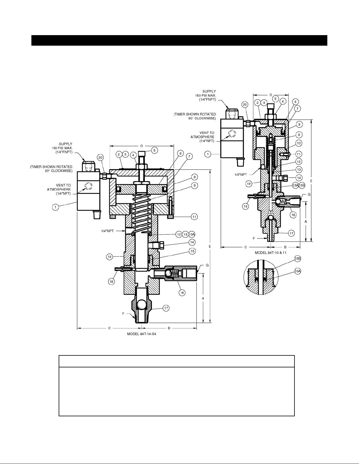
1. Figure 1 of this manual is the
sectional drawing and parts
list for the LINC84T-10, 11 &
14ChemicalMeteringPump.
2. Figure 2 of this manual is the
sectional drawing and parts
list for the LINC84T-12
Chemical Metering Pump.
Installation:
The LINC84T-10, 11, 12 & 14 re-
quire a flooded suction and must
be located lower than the chemical
supply tank. Vertical installation
of the piston housing is required.
1. Connect the suction line
through a filter or strainer to
the suction check valve (fig.
1, item 17 or fig. 2, item 16).
2. Connectthedischargelineto
the desired location.
Note:An in-linecheckvalve at the
point of injection is recommended
to prevent back flow to the pump
during shutdown or servicing.
3. Connect a supply pressure
line to the timer (fig. 1, item 1
or fig. 2, item 1). Air is the
recommended supply; how-
ever,anydryfilteredgasmay
beused. Thesupplypressure
to the timer must be regu-
lated between 15 psig and
110 psig.
4. Settheregulatortotheproper
pressure to overcome the
discharge pressure required
by the pump. Refer to the
paragraph on "Amplication
Ratio" in this manual to
determine the correct supply
pressure.
5. To prime the pump, loosen
the bleed screw (fig. 1, item
18 or fig. 2, item 18). Allow
the liquid (chemical) to flow
into the pump chamber,
ventingthetrappedairorgas.
Tighten the bleed screw.
6. Start the pump and run for a
minimum of one minute.
Open the bleed screw again
and evacuate all the remain-
ing air or gas from the pump
chamber.
7. Using a rate gauge, set the
desired pumping rate by
adjusting the timer knob and
stroke adjustment screw.
Thetimercanbesettostroke
the pump from 4 strokes/
minute to the maximum rate
for the particular pump being
used. See selection chart in
this section of the manual.
8. The stroke length is adjusted
by rotating the stroke adjust-
ment screw (fig. 1, item 5 or
fig. 2, item 4) on top of the
piston housing (fig. 1, item 8
or fig. 2, item 6). Loosen the
jam nut and adjust the stroke
adjustment screw as neces-
sary (fig. 1, item 4 or fig. 2,
item 5). Lock down the jam
nutafteranyadjustmentsare
made.
Note: Theminimumstrokeonthe
84T-10, 11 & 12 is 1/8" and 1/4" on
the 84T-14.
Maintenance:
Refertoallsectionaldrawingand
parts list in this manual. All repairs
should be performed in a clean
environment.
The following steps must be
taken before proceeding with any
maintenance operations:
Removing the Pump from Ser-
vice:
1. Rotate the control knob on
the timer to the "O" position.
2. Disconnect the supply
pressure from the timer.
3. Close the upstream and
downstream valves on the
chemical lines.
4. Open the bleed screw to
release the pressure in the
pump.
5. Disconnect the suction and
discharge lines from the
check valves.
Timer,
Figure 1, item 1 or Figure
2, item 1 & Figure 3:
1. Disconnect the supply
pressure from the timer.
2. Rotate the timer counter-
clockwise on the pipe nipple
that connects it to the piston
housing until the timer is
vertical with the supply pres-
sure port pointing down.
3. Loosen and remove the two
screws from the timer (fig. 3,
item1).
Untitled-4 2/19/2004, 4:23 PM7