Lince ZENITH GOLD 869 Series User manual

GOLD 869 UNIVERSAL TRANSCEIVER
ART. / ITEM:
9588-GOLD-TXRX-M
GOLD 869 UNIVERSAL
TRANSCEIVER
MADE IN ITALY
The CE declaration of this item can be
found on the www.lince.net website. installation, operation and maintenance manual

2
LINCE ITALIA S.p.A.
CONTENTS
1 OVERVIEW.....................................................................................................................................................................................................................................................3
1.1 WIRELESS DEVICE OF THE GOLD 869 SERIES ........................................................................................................................................................................3
1.2 ACCESSORIES ................................................................................................................................................................................................................................4
1.3 PACKAGE CONTENT ......................................................................................................................................................................................................................4
1.4 SPECIFICATIONS............................................................................................................................................................................................................................5
1.5 INTERNAL PARTS DESCRIPTION.................................................................................................................................................................................................5
1.5.1 Terminal block description ........................................................................................................................................................................................................5
2 INSTALLATION..............................................................................................................................................................................................................................................6
3 PROGRAMMING AND BASIC MANAGEMENT WITHOUT SOFTWARE................................................................................................................................................6
3.1 DEVICES STORAGE .......................................................................................................................................................................................................................6
3.2 DEVICES ERASURE........................................................................................................................................................................................................................6
3.3 DEVICES STATUS DISPLAY...........................................................................................................................................................................................................6
4. PROGRAMMING AND EXTENDED MANAGEMENT VIA SOFTWARE...................................................................................................................................................7
4.1 CONNECTION TO THE WI-FI HOT SPOT OF THE DEVICE .......................................................................................................................................................7
4.2 SOFTWARE INSTALLATION ..........................................................................................................................................................................................................7
4.3 FIRST CONNECTION .....................................................................................................................................................................................................................7
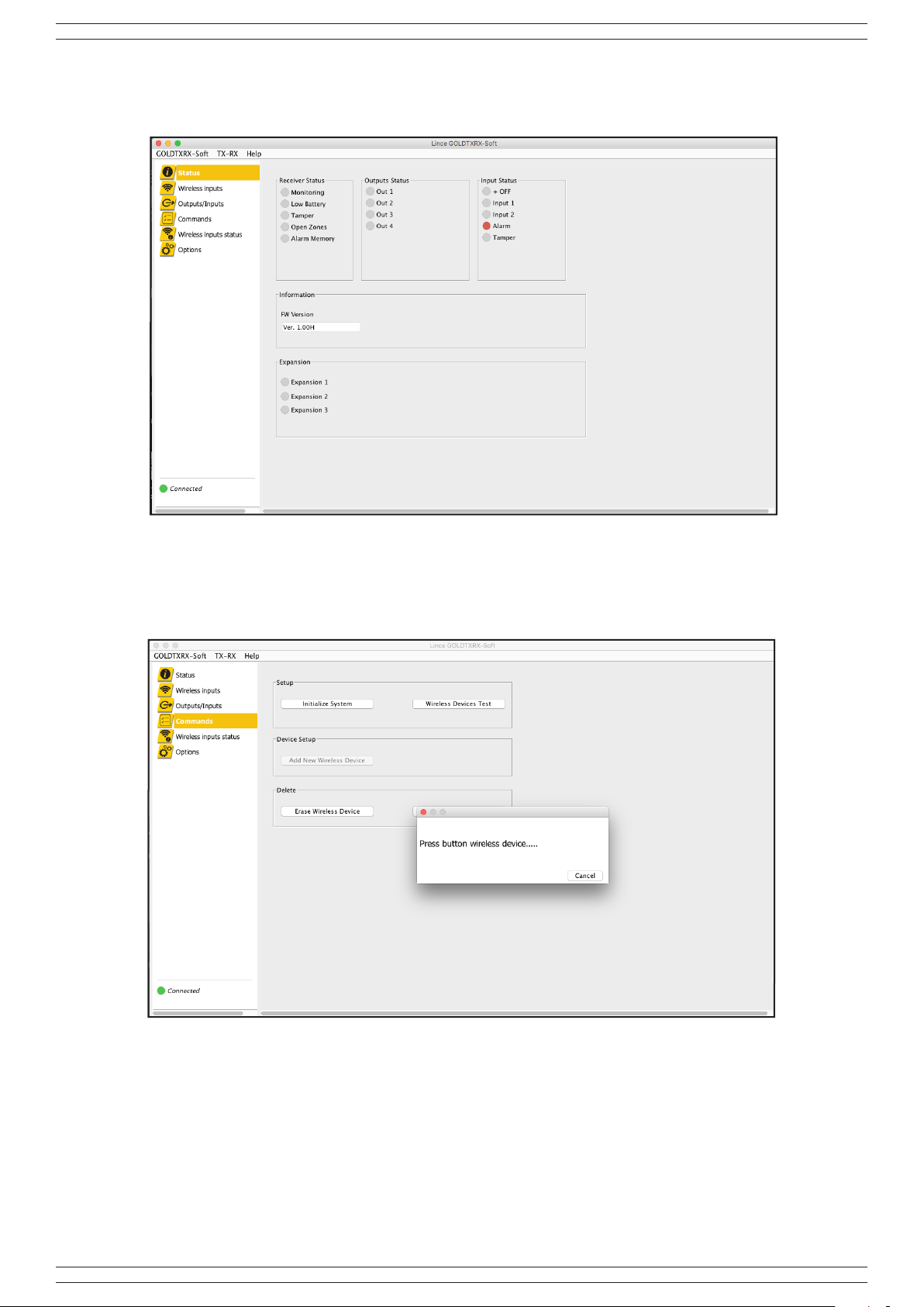
4.4 STATUS ...........................................................................................................................................................................................................................................8
4.5 WIRELESS DEVICES STORAGE ...............................................................................................................................................................................................................8
4.5.1 Indoor dual technology detector storage ..................................................................................................................................................................................9
4.5.2 Storage of dual technology detector BABY ..............................................................................................................................................................................9
4.5.3 Triple BOBBY technology detector storage ............................................................................................................................................................................10
4.5.4 Shutter contact storage ...........................................................................................................................................................................................................10
4.5.5 Magnetic contact storage ........................................................................................................................................................................................................11
4.5.6 Wireless remote control storage..............................................................................................................................................................................................11
4.5.7 Siren storage ..........................................................................................................................................................................................................................12
4.5.8 Wireless output storage ..........................................................................................................................................................................................................12
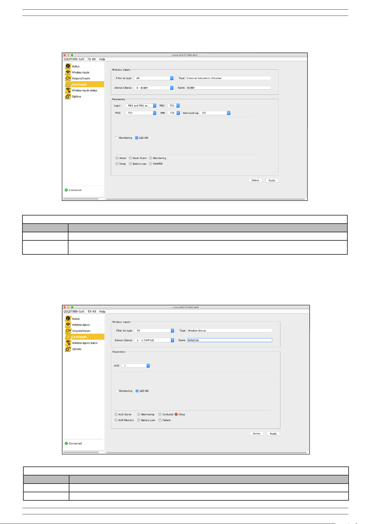
4.6 WIRELESS INPUT MANAGEMENT .........................................................................................................................................................................................................13
4.6.1 Variation of wireless device parameters and selective erasurerziale .....................................................................................................................................14
4.6.2 Wireless device total erasure ..................................................................................................................................................................................................14
4.6.3 Clear alarms memory..............................................................................................................................................................................................................14
4.6.4 Wireless inputs status .............................................................................................................................................................................................................14
4.6.5 Wireless device test ................................................................................................................................................................................................................14
4.6.6 “Sleep” function .......................................................................................................................................................................................................................14
4.7 OUTPUTS/INPUTS MANAGEMENT...............................................................................................................................................................................................15
4.8 OPTIONS MENU ..............................................................................................................................................................................................................................16
5 MENÙ BAR...................................................................................................................................................................................................................................................17
5.1 GOLDTXRX-SOFT MENU ...............................................................................................................................................................................................................17
5.2 TX-RX MENÙ ....................................................................................................................................................................................................................................17
5.2.1 Firmware update .....................................................................................................................................................................................................................18
5.3 HELP MENU......................................................................................................................................................................................................................................18
6 COMPATIBLE OPERATING SYSTEMS ....................................................................................................................................................................................................18
7 MAINTENANCE AND PERIODIC INSPECTIONS ...................................................................................................................................................................................18
8 DISPOSAL AND SCRAPPING ..................................................................................................................................................................................................................18
9. CONNECTION EXAMPLES .......................................................................................................................................................................................................................18
10. TRANSCEIVER CONFIGURATION ..........................................................................................................................................................................................................20
The information in this manual has been issued with care, but LINCE ITALIA S.p.A. will not be responsible for any errors or omissions. LINCE ITALIA
S.p.A. reserves the right to improve or modify the products described in this manual at any time and without advance notice.Terms and conditions
regarding assistance and the product warranty can be found at LINCE ITALIA’s website www.lince.net. LINCE ITALIA S.p.A. makes it a priority to
respect the environment. All products and production processes are designed to be eco-friendly and sustainable.
This product has been Made in Italy.
• ThecompanyhasacertiedsystemofqualitymanagementaccordingtoISO9001:2008(n°4796-A)standard.
• ThecompanyhasacertiedsystemofenvironmentalmanagementaccordingtoISO9001:2004(n°4796-E)standard.
• ThecompanyhasacertiedsystemofhealthandworksecuritymanagementaccordingtoISO45001:2018(n°4796-I)standard.

3
LINCE ITALIA S.p.A.
1. OVERVIEW
The 9588-GOLD-TXRX-M transceiver is a radio device operating on the 868 and 869 MHz frequencies compatible with the GOLD 869
series devices. The device allows you to associate the GOLD series devices with any other brand alarm control panel equipped with
wired inputs. Up to 8 radio devices can be memorized on the master transceiver, 4 outputs controled by remote control 9511-GOLD-
RC and 2 inputs that can drive as many 9557-GOLD-OUT outputs.The storage and conguration of the devices can take place
directly via the multifunction button on the board or through the GOLDTXRX-Soft software which also allows you to change the
default settings of the devices and to change the factory settings of the outputs. It is also possible to connect up to a maximum of 3
expansions 9589-GOLD-TXRX-S by addingup to a maximum of 24 radio inputs to the 8 already present.
9502-GOLD-BOBBY-AM
The detector, consisting of 2 PIRs and 1 x 24 GHz microwave, has been designed to deliver maximum outdoor
performance in terms of detection, immunity to false alarms and to the wireless transmission distance. With internal
adjustments and settings, the detection stage allows a protection area of 12 m with a triple AND set 85° opening and
can actually be considered as PET IMMUNITY. Different settings make it safe and exible; security is also ensured
by the double optical anti-masking, one for each PIR.
Made entirely of UV-resistant polycarbonate, it is equipped with a Fresnel lens made in U.S.A. and
a stainless steel wall mounting bracket.
It is also available in dual PIR version with code 9514-GOLD-BOBBY/E and 9553-GOLD-BOBBY-AM-E dual PIR
with anti-mask. Also available in curtain versions 9554-GOLD-BOBBY-AM-T double technology with anti-mask,
9555-GOLD-BOBBY-AM-T-E dual PIR with anti-mask and 9556-GOLD-BOBBY-T-E dual PIR without anti-mask.
9507-GOLD-TP
Indoor wireless magnetic contact for signals when doors and windows are opened. Designed to provide maximum
performance in terms of detection, immunity to false alarms and wireless transmission distance. Additional input for
another magnetic contact or rope detector for window blinds or inertial contact with impulse discrimination that can
be selected from the control panel. Range up to 600 m in free air
Also available in brown with code 9508-GOLD-TP/M.
9528-GOLD-TP-L
Same features as the 9507-GOLD-TP but with a range of up to 1.5 km in free air.
Also available in brown with code 9529-GOLD-TP-L/M.
9503-GOLD-BABY
The curtain detector for doors and windows consists of 2 PIRs and 1 x 24 GHz microwave and has been designed
to deliver maximum outdoor performance in terms of detection, immunity to false alarms and to the wireless
transmission distance. The detection stage allows the crossing direction to be recognised and the precise microwave
setting enables PET IMMUNITY if set to triple AND and tted with double anti-masking, one for each PIR. Made of
polycarbonate, it is equipped with Fresnel lenses made in U.S.A. that are particularly resistant to UV rays.
It is also available in dual PIR version with code 9515-GOLD-BABY/E.
9504-GOLD-DT
The indoor detector wireless double technology consists of 1 PIR and 1 x 24 GHz microwave with anti-mask.
Designed to provide maximum performance in difcult environments in terms of detection, immunity to false alarms
and wireless transmission distance. Fitted with a bracket with a metal lock that can be wall mounted - at an ideal
height of 2.1 m and detects up to a maximum of 12 m with a 90° opening. Three signal LEDs for PIR, MW and
alarm. Also available in the curtain version (with 8° opening) 9505-GOLD-DT/T; 9525-GOLD-IR volumetric infrared
without anti-mask; 9526-GOLD-IR/T curtain infrared without anti-mask; 9531-GOLD-DTE double technology
without anti-mask; 9532-GOLD-DTE/T curtain double technology without anti-mask.
9506-GOLD-DT/Z
The indoor detector wireless double technology for ceiling installations consists of 1 PIR and 1 x 24 GHz microwave
with anti-mask. Designed to provide maximum performance in difcult environments in terms of detection, immunity
to false alarms and wireless transmission distance. Circular detection with a maximum diameter of 11.4 m if installed
at a height of 4 m.Three signal LEDs for PIR, MW and alarm. Also available in the DT without anti-mask version
9536-GOLD-DTE/Z and only infrared without anti-mask 9526-GOLD-IR/T
9509-GOLD-LESW
Wired contact for window blinds and roller shutters with a wireless section. The detector has been designed to deliver
maximum semi-outdoor performance in terms of detection, immunity to false alarms and wireless transmission
distance. Impulses are set directly from the control panel. Placed inside the box, with the wire secured at the bottom
of the shutter protects it from being opened, cut and broken, thereby allowing the alarm to be triggered even with
the shutter is not fully closed. ABS body with lateral appendices for slides to be applied (optional) art. 1829-LESW/
ST which facilitate their fastening. Patented internal leverage system to prevent the micro switch stall position.
9587-GOLD-AG
Flooding detector for signaling environments invaded by water
1.1 WIRELESS DEVICES OF THE GOLD 869 SERIES
Below is a list of wireless devices compatible with the transceiver:

4
LINCE ITALIA S.p.A.
9511-GOLD-RC
Wireless remote control for control panel management. All combinations related to arming, sectioning, choice of
programs and disarming can be implemented with just two buttons. The three signal LEDs allow you to make
selections (program type), using the rst button, and conrm the choice made, using the second button. Aesthetically
pleasing and ergonomic in use. Completely bidirectional, it receives the command execution response from the
control panel. It allows you to view the system state, open input and alarm memory.
OBLO 869 SIRENS
Its design is based on a new concept to facilitate installation and maintenance. The siren is made entirely of
polycarbonate, resistant to impact and UV rays; its unconventional aesthetics distinguish it among many. Powered
by a non-rechargeable lithium battery (art. 001515/00251AA, not supplied) it is also equipped with a WIN (Wired
Interface Network) power supply system that allows the siren to be powered in three different modes: non-
rechargeable lithium (not supplied) - non-rechargeable lithium with mains power supply via 12 Vdc adapter (not
supplied) - lead battery 12 V 2.2 Ah (not supplied) with mains power supply via 12 Vdc adapter (not supplied). The
sound frequency is 1,800 Hz and the sound pressure - volume, adjustable from the control panel - is 115 dB @ 1 m
if battery powered and 119 dB @ 1 m if powered by win. Maximum continuous acoustic alarm time of 3 min if battery
powered and 5 min if powered by win. The siren is protected from being opened, tampered with and wall removed
by means of a micro switch. Optical signalling occurs by means of a high efciency LED. The electronic board has
been designed and epoxy treated for outdoor installations. Monitoring optical message ashlighting every 60 s (only
in win mode). Complies with EN50131-4, environmental class IV, IP43 protection rating, operating temperature:
-25°C ÷ + 60°C. Dimensions: 277 x 251 x 72 mm. Available in two versions: 9510-GOLD-OBLO and 9518-GOLD-
OBLO/L with anti-foam, anti-ame, WIN supply.
9557-GOLD-OUT
The wireless output module extends the functions of the GOLD system and has a relay output that can be piloted
from the control panel or dialer for “Apply”tions, such as: activate camera recording (videoverication), control an
electric lock, perform automated tasks, such as turn an electrical appliance on and off (together with an external relay,
not supplied). The wireless output can be associated with a detector to be activated when an intrusion is detected.
It also has the AND mode to be activated only when the intrusion has been detected by at least two detectors. The
wireless output module also has a usable input, for example, to verify that the load has been activated.
9560-GOLD-PRIME
Outdoor wireless siren with optical and acoustic signals, protected against opening and wall removal. Made of ABS,
it is powered by a 6 V battery that conforms to EN50131-4, environmental class IV, IP43 protection rating, operating
temperature: -25°C ÷ + 60°C.
B
A
C
Fig. 1
1.3 PACKAGE CONTENT
The contents of the package are shown below:
Table 1
Part Description
ADevice
BProduct manual
CPendrive containing the programming software
1.2 ACCESSORIES
Below is a list of accessories compatible with the transceiver:
9589-GOLD-TXRX-S
Expansion module that allows you to add 8 wired outputs in addition to those already on board. It is possible
to connect up to a maximum of 3 expansions up to a maximum of 32 outputs and as many memorable radio
devices.

5
LINCE ITALIA S.p.A.
1.4 SPECIFICATIONS
Power supply 12Vdc Total wireless devices up to 32 (detector, remotes, ecc)
Power
consumption 80 mA NC relay zone outputs up to 32
Transmission
frequencies
869,40 MHz-869,65 MHz 1 canale, 868,00 MHz-
868,60 MHz 4 canali NC area 24 h 1
FH Frequency Hopping Outputs controlable by
remotes 4
TDMA Time Division Multiple Access Dimensions 170 x 107 x 30 mm
AES Advanced Encryption Standard Working temperature 5°C ÷ 40°C
Range up to 1.5 km in free air (the range depends on the type
and the combined device) Color White
Table 2
Part Description
AWall xing holes
BHot-Spot reset button for the Wi-Fi module
CWi-Fi module status LED, emits only one type of
ashing to indicate correct module operation
DTear plate xing hole
EAnti-removal and anti-opening tamper
FTerminal block for tamper connection
GExpansions connector
HDevice status LEDs
IInput/output terminal block
LMultifunction button
MDevices supervision status signaling LED
NDevices supervision status signaling LED
ODevices tamper and antimasking signalling LED
PPre-cut for cable passage
1.5 INTERNAL PARTS DESCRIPTION
12V 1 2 3 4 5 6 7 8
01 02 03 04 +OFF I1 I2
AL BA S AS AS
TP
A
BC
D
M
F
L
E
G
H
I
Fig. 2
A
O
I
N
Table 3
TERMINAL
BLOCK DESCRIPTION TERMINAL
BLOCK DESCRIPTION
12 V Power supply +OFF
System status input activable due to arrival or
lack of negative. If the control panel to which it
is connected does not have a compatible output,
connect the 12 V terminal
Reference mass, negative power supply (all the
masses are common) I1, I2 Pilot inputs of the associated wireless outputs.
Programmable as arrival or lack of positive
1÷8 NC relè output AL Output activable due to lack or arrival of positive
to sound any stored sirens
Reference mass, negative power supply (all the
masses are common) BA Open collector negative output present with the
device battery discharged.
01÷04 Open collector output for remote control SOpen collector negative output present in case of
smonitoring signal
Reference mass, negative power supply (all the
masses are common) AS Connect a 24h tamper line from the control panel
to these two terminals
1.5.1 Terminal block description
P
P
P

6
LINCE ITALIA S.p.A.
2. INSTALLATION
To proceed with the correct installation of the transceiver on the wall, follow the instructions below:
• unscrew the four closing screws of the cover;
• open the pre-cuts of the cable passage according to your needs;
• fasten the plastic wall base through the holes present and using suitable plugs, be careful also to x the anti-tear plate in order
to guarantee its function;
• power supply the board
• if you decide to proceed with the basic programming, refer to the contents of the relative paragraph;
• if you decide to proceed with the extended programming, refer to the contents of the relative paragraph;
• make the appropriate electrical connections;
• close the cover after programming
3. PROGRAMMING AND BASIC MANAGEMENT WITHOUT SOFTWARE
NOTE:
Both programming procedures must be carried out with the cover open so as to open the tamper, otherwise it is not possible
to modify or memorize new devices.
3.1 DEVICES STORAGE
• This programming mode is useful for quickly storing radio devices without having the possibility to change their default detection
parameters and without changing the default settings of the outputs for which the use of the software is required. Then follow
the steps below:
• Open the device tamper to proceed with programming;
• press the multifunction button once and wait for the device monitoring status LED to start ashing;
• long press the multifunction button until you hear a long sound produced by the transceiver;
• entry into programming mode is indicated by the intermittence of the device tamper status LEDs and supervision status and the
rst free position among the eight available (32 if there are slave boards connected);
• store the device referring to what is reported in its manual;
• conrmation of successful storage will be indicated by the issuing of a long sound by the transciever and the automatic exit from
the storage procedure;
• pto memorize other devices repeat the procedure;
• to exit the storage, press the multifunction button again.
3.3 DEVICES STATUS DISPLAY
During normal operation of the transceiver, various information is displayed on the LEDs as shown in the “devices status display”
table. To obtain more detailed information, it is possible to enter the different menus by pressing the Multifunction button for the
number of times shown in the detailed device status display table
3.2 DEVICES ERASURE
To selectively delete the stored devices, press the multifunction button until the sabotage signaling LED lights up. At this point, keep
the button pressed until the device status LEDs light up: only those relating to the positions occupied will light up; if any expansions
9589-GOLD-TXRX-S are connected, they will also light up on them in sequence. Again using the multifunction button, select the
device to be deleted by pressing the button until the corresponding LED ashes; keep the button pressed until the buzzer of the card
emits a short sound conrming the cancellation. To exit the erasure procedure, press the button until you get to the last stored device
(including the expansions) and the total shutdown of all the LEDs on the card.
Table 4 - Devices status display
LED Description Slow ashing Fast ashing Staeady ON
1 2 3 4
Device status LEDs Sleeping device Device alarm memory Alarm
Devices supervision status signaling LED n. a. n. a. At least one device
in monitoring alarm
Device status and fault LED n. a. n. a. At least one device
with low battery
Device sabotage and masking signalling LED n. a. n. a.
At least one device
in sabotage or
masking
NOTE:
• refer to the next section where the extended programming is illustrated to know in detail the parameters that are set by
default;
• the alarm memories are automatically deleted after having carried out a complete visualization of all the three signaling
LEDs either by pressing the multifunction button for a long time or by changing the status of the OFF terminal.

7
LINCE ITALIA S.p.A.
4. PROGRAMMING AND EXTENDED MANAGEMENT VIA SOFTWARE
This programming and management mode allows you to program and modify the default parameters of devices and outputs. Then
follow the steps below.
4.2 SOFTWARE INSTALLATION
• Open the device tamper to proceed with programming;
• make sure that the latest version of jvm (java virtual machine) is present on your computer,
otherwise download the latest version from the site https://www.java.com;
• download the latest version of the GOLDTXRX-Soft program from the LINCE website after
logging in;
• If you do not have an internet connection, you can take the software from the pendrive
present in the product packaging;
• open the GOLDTXRX-Soft folder and inside it, click on the GOLDTXRX-Soft.jar le;
• enter the default password “lince” which can be changed later.
Fig. 3
4.1 CONNECTION TO THE WI-FI HOT SPOT OF THE DEVICE
Before using the software, you must connect to the Wi-Fi hot spot. Power up the card, open the Wi-Fi network settings of your
computer, search for the “Dongle-WiFi-xxxxxx” network and enter the default password “password” which cannot be changed.
4.3 FIRST CONNECTION
Before proceed with the use of the software, select “GOLDTXRX-Soft”. → “lingua” and select “ENglish”. After this, click on the
menu bar under “TX-RX” → “connect” to connect the software to the transceiver and allow the download of the currently existing
conguration.
Fig. 4
NOTA:
• keep in mind that the device hot-spot will be visible only for three minutes from the power on and once connected to the
computer it will remain active for the entire time of the connection;
• pressing the B button on the card, the Wi-Fi module resets and becomes visible, if pressed for 5 times the Wi-Fi module
is initialized.
Table 5 - Detailed display of device status
Selected
menù Descritpion Actions on
multifunction
1 2 3 4
Device status LEDs
Slow ashing Fast ashing Steady ON
Devices supervi-
sion status signa-
ling LED
1 n. a. n. a. The device is in
monitoring alarm
Battery status and
device failure LED 2
Device failure
(Refer to the siren manual in use
to identify possible faults)
Wireless device low battery
signal n. a.
Device sabotage
and masking si-
gnaling LED
3 Wireless device masking alarm Radio device sabotage signal n. a.

8
LINCE ITALIA S.p.A.
4.4 STATUS
The “Status” screen offers an overview of the status of the devices and outputs of the control panel and the presence of expansion
modules.
Fig. 6
4.5 WIRELESS DEVICES STORAGE
To store GOLD 869 devices, go to the “Commands” item and click on the “Add New Wireless Device” item. When prompted by the
software, proceed with storage the device according to the instructions in the relative manual.
Fig. 5
After setting the operating parameters of the radio device, always press “Apply” to send the parameters to the device.
After each storage, the software proposes the “Commands” screen, press “Add New Wireless Device” again to memorize another
device.

9
LINCE ITALIA S.p.A.
4.5.1 Indoor dual technology detector storage
The dual technology indoor detector screen (volumetric, curtain, ceiling, etc.) allows you to set the sensitivity of the microwave, the
PIR, the anti-masking and the operating logic.
Table 6 - Dual technology detector options
Option Description
Monitoring Enables the device to send monitoring signals
LED ON When the device is in alarm and battery powered, the LED lights up for 6 seconds. If the WIN is present, the LED lights up every time it
detects..
Fig. 7
4.5.2 Storage of dual technology detector BABY
The BABY triple technology detector screen allows you to set the sensitivity of the microwave, the PIRs, the anti-masking, the
operating logic and the direction of crossing (CWS).
Table 7 - Dual technology detector options
Option Description
Monitoring Enables the device to send monitoring signals
LED ON When the device is in alarm and battery powered, the LED lights up for 6 seconds. If the WIN is present, the LED lights up every time
it detects..
Fig. 8

10
LINCE ITALIA S.p.A.
4.5.3 Triple BOBBY technology detector storage
The triple BOBBY technology detector screen allows you to set the sensitivity of the microwave, the PIRs independently, the masking
and the operating logic.
Table 8 - Triple technology detector options
Option Description
Monitoring Enables the device to send monitoring signals
LED ON When the device is in alarm and battery powered, the LED lights up for 6 seconds. If the WIN is present, the LED lights up every time
it detects..
Fig. 9
Fig. 10
4.5.4 Shutter contact storage
The shutter contact screen allows you to set the number of impulses after which the alarm signal must be triggered on the AUX input.
From the “AUX” drop-down menu, select a value including 2, 4, or 8 impulses.
Table 9 - Shutter contact options
Option Description
Monitoring Enables the device to send monitoring signals
LED ON When the device is in alarm and battery powered, the LED lights up for 6 seconds.

11
LINCE ITALIA S.p.A.
4.5.5 Magnetic contact storage
The magnetic contact screen allows you to activate or not the magnetic reed (active by default), activate the external contact “AUX”
(deactivated by default), and various attributes whose details are shown in the following table.
To set the number of impulses after which the alarm signal must be triggered on the auxiliary input, from the drop-down menu “AUX”
select a value between NC (normally closed), 2, 4, or 8 impulses for roller shutter or inertial type contacts.
Fig. 11
Table 10 - Magnetic contat options
Option Description
Monitoring Enables the device to send monitoring signals
LED ON When the device is in alarm and battery powered, the LED lights up for 6 seconds.
4.5.6 Wireless remote control storage
The memorization screen of the radio control allows you to memorize it and change its name. The output (1-32) on which the radio
control is stored must not be connected to the control unit.
Fig. 12
The choice of the combination of outputs (O1-O4) takes place through the rst button of theremote control (high) and sending it with
the second (low) referring to the following table of combination between the LEDs and the outputs.

12
LINCE ITALIA S.p.A.
Table 11 - Remote control options
LED Output
Red Output 1
Yellow Output 2
Green Output 3
Yellow Output 4 is enabled with a single press of button 2 on the remote control
NOTE:
All remote controls have the same privileges, therefore it is not possible to differentiate them and they do not manage the
display and interrogation of the system status.
Table 12 - Siren options
Option Description
Monitoring Enables the device to send monitoring signals
LED ON When the device is in alarm and battery powered, the LED lights up for 6 seconds. See product manual for details about the functioning
if WIN is connected
Local tamper If open, the siren sounds regardless of communication with the transceiver
Advanced functions If available on the model in possession, it allows you to enable the antifoam, the anti-ame and the anti-approach systems
Beep If enabled, a short sound is emitted by the siren at every arming and disarming
Fig. 13
4.5.7 Siren storage
The siren screen allows you to set the siren volume by choosing a value between 25% and 100% in 5% steps from the relative drop-
down menu. In addition to this, you can set the type of sound, whether type A or type B (default), and the other attributes shown in the
table below. The output (1-32) on which the siren is stored must not be connected to the control panel.

13
LINCE ITALIA S.p.A.
4.6 WIRELESS INPUT MANAGEMENT
All the screens and functions useful for managing wireless devices such as deleting, viewing and changing parameters are reported.
4.6.1 Variation of wireless device parameters and selective erasurerziale
To change the parameters of the stored radio devices, go to “Wireless Inputs” and from the drop-down menu “device choice” select
the name of the device on which you want to operate. At the end of the operation, press “Apply”.
Fig. 14
To delete the single device, always select it from the drop-down menu and press the “Delete” button, conrming when requested.
Fig. 15
4.5.8 Wireless output storage
The “Wireless Output” section allows you to congure the duration of the switching and the association with one or both of the wired
inputs (default input 1), the stand-by status of the output and the other parameters are shown in the following table.
The relay operating logic can be set as normally open NO or normally closed NC (default). The duration of the changeover can be
impulsive (3 s) or it is possible to set the duration by pressing “Apply” after entering the desired value. By default it is set as a step -
by - step.
Table 13 - Wireless output options
Option Description
Monitoring Enables the device to send monitoring signals
LED ON When the device is in alarm and battery powered, the LED lights up for 6 seconds.
I1 - I2 Select which input the output is associated

14
LINCE ITALIA S.p.A.
4.6.2 Wireless device total erasure
To delete the radio devices go to “Commands” and click on “Erase Wireless Device” and conrm when requested.
Fig. 16
4.6.3 Clear alarms memory
To clear the alarm memories go to “Commands” and click on “Clear alarms memory” and conrm when requested.
Fig. 17
4.6.4 Wireless inputs status
The “wireless inputs status” screen allows you to view the alarm signals and the general status of the stored devices. Refer to the
contents of the “legend” to nd out what type of information can be displayed. From the “Group Choice” drop-down menu it is possible
to choose which group of devices to display: from 1 to 16 and from 17 to 32. By double clicking on a stored device it is possible to
receive information such as the signal level of the device, the FW version and the transmission frequency.
By clicking on the “RF eld Analysis” button it is possible to receive information relating to the packets transmitted (TX), received
(RX), belonging to the system but damaged (Error) and not belonging to the system (Noise).
NOTE:
In some cases, due to the speed of opening and closing of the detector, in particular with those of movement, it may happen
that the opening of the area is not visible in real time; however, the signaling remains in the memories.

15
LINCE ITALIA S.p.A.
4.6.5 Wireless device test
The “Wireless Device Test” section sends all the radio devices present for 4 minutes in test mode. Press the “Test Radio” button and
open an area of the device for which you want to receive information. These last are shown, as in the example below, in a screen that
can be exported to a text le using the appropriate “export” button.
Fig. 18
4.7 OUTPUTS/INPUTS MANAGEMENT
The “Outputs / Inputs” section allows you to change the default settings of the outputs that can be controlled via remote control and
the polarity of the inputs on the board. The default settings are shown on the screen. After changing the settings, press “Apply” to
make them effective.
Fig. 19
4.6.6 “Sleep” function
When the devices do not detect the presence of the transceiver, after a few minutes they enter a low consumption dormant state (in
which they do not transmit and do not detect). Once the devices have entered this mode after one hour, they reactivate for a minute
checking the presence of the transceiver’s frame and, if not present, return to a dormant state until the next hour. The devices will
appear excluded in the “radio input status menu” with the letter “D” as an attribute.

16
LINCE ITALIA S.p.A.
4.8 OPTIONS MENU
The options menu allows you to change the number of non-monitoring cycles after which the transceiver opens the related open
collector line (terminal S). The number of supervision cycles can be selected from 1 to 6.
Fig. 21
5. MENÙ BAR
Fig. 22
5.1 GOLDTXRX-SOFT MENU
The GOLDTXRX-Soft menu allows you to access various items such as: info, password change
and language change. The “Info” menu allows you to view the software version and a direct link
to the Lince Italia web page.
Fig. 20

17
LINCE ITALIA S.p.A.
5.2 TX-RX MENÙ
By pressing on the “Connect” item of the “TX-RX” menu, you can connect to the receiver as already illustrated at the beginning of this
manual, the “Demo” item allows you to view only the off-line operation of the software without connecting to the device.
5.2.1 Firmware update
The item “Updating FW” allows you to update the rmware of the transceiver. Click on the item and select the le you just downloaded
from the www.lince.net site
Fig. 24
Fig. 23
5.3 HELP MENU
IThe “Help” menu allows you to view an electronic version of this manual.
Fig. 25 Fig. 26
Conrm the next two alert messages and wait for the transceiver to restart.

18
LINCE ITALIA S.p.A.
Fig. 27
9. CONNECTION EXAMPLES
The diagram shown represents a typical connection to a generic wired control panel of any other manufacturer. In particular, three
wired inputs, the sabotage line and the 4 outputs of the remote control were connected by way of example. In particular, the last ones
have been connected to as many external inputs for program switching: the rst three have been connected for the switching of single
programs, while the fourth can be used for total amrming.
12V 1 2 3 4 5 6 7 8
01 02 03 04 +OFF I1 I2
AL BA S AS AS
TP
12V 1 2 3 4 AS AS PR1 PR2 PR3 PRT ST
CONTROL PANEL OF
ANY BRAND
6. COMPATIBLE OPERATING SYSTEMS
The operating systems compatible with the GOLDTXRX-Soft are:
• Windows starting from version 7;
• Mac OS starting from version 10.12;
• Linux Kernel starting from version 4.15.11 for X64 and from version 4.14.27 for ARM32 and ARM64.
7. MAINTENANCE AND PERIODIC INSPECTIONS
To make sure the control panel works properly, replace the backup battery every 2 years.
ATTENTION! DO NOT use chlorinated products, abrasive products or alcohol to remove particularly noticeable
dirt.
1. Clean the lid with a cloth dampened with water.
2. Then wipe with a dry cloth.
ATTENTION!
If, after storing the devices, the Transceiver is switched off or the control panel and devices are out of range, it is
recommended to remove the batteries from the devices in order to preserve their autonomy
8. DISPOSAL AND SCRAPPING
1. Unscrew the screws that secure the front lid and remove it.
2. Disconnect the board: disconnect all terminal blocks on the terminal board (see Fig. 3).
3. Divide the parts according to their type and dispose of them according to the laws in force.
ATTENTION!
Do not disperse the components and any other material of the product into the environment.
Consult authorised consortia for the disposal and recycling of materials.

19
LINCE ITALIA S.p.A.
The terminals of the control panel to which the board is connected are shown in the following table
Table 14 -
TERMINAL
BLOCK DESCRIPTION TERMINAL
BLOCK DESCRIPTION
12 V Power supply PR1 ÷ PR3 Arming commands 1 to 3
Reference mass PRT Total program arming command
1÷4 Wired inputs ST System status
AS - AS Tamper line Reference mass
The following diagram shows an example of connection of the master board with three other slave boards using the cable supplied
with the same slave boards.
12V 1 2 3 4 5 6 7 8
01 02 03 04 +OFF I1 I2
AL BA S AS AS
TP
1 2 3 4 5 6 7 8
TP
1 2 3 4 5 6 7 8
1 2 3 4 5 6 7 8
TP
TP
Fig. 28
9588-GOLD-TXRX-M 9589-GOLD-TXRX-S 9589-GOLD-TXRX-S 9589-GOLD-TXRX-S
When one or more slave boards are connected, it is necessary to set the correct address of the board simply by positioning the jumper
on two different pins depending on the boards
SLAVE 1 SLAVE 2 SLAVE 3MASTER
1 2 3 4 5 6 7 8
AL
1 2 3 4 5 6 7 8
AL
Fig. 29
In the case of the SLAVE2 board,
the jumper must be connected to
the EXP3 position.
1 2 3 4 5 6 7 8
AL
EXP4 EXP3
In the case of the SLAVE1 board,
simply remove the jumper.
1 2 3 4 5 6 7 8
AL
EXP4 EXP3
EXP4 EXP3
1 2 3 4 5 6 7 8
AL
EXP4 EXP3
In the case of the SLAVE3 card,
the jumper must be connected to
the EXP4 position.
NOTES:
• In order to ensure correct recognition of the sequence of inputs, it is necessary
to comply with the above and in the order indicated. In the case of connection,
for example of two expansions, the slave connected directly to the master must
have the jumper disconnected, while the one connected to the rst must have
the jumper inserted in the “EXP3” position;
• The connections of the slave cards cannot be made “hot”, therefore it is neces-
sary to disconnect the power supply from the master card, connect the slave
cards and power the master card again.

001530/00985BA Rev 0
LINCE ITALIA S.p.A.
Via Variante di Cancelliera, snc
00072 ARICCIA (Roma)
Tel. +39 06 9301801
Fax +39 06 930180232
www.LINCE.net
10. TRANSCEIVER CONFIGURATION
INSTALLER INFO
name and surname
telephone number mobile
email
NOTES
RF
input Description RF
input Description
1 9 17 25
2 10 18 26
311 19 27
4 12 20 28
5 13 21 29
6 14 22 30
7 15 23 31
8 16 24 32
Wired Outputs
N° Name
01
02
03
04
WIRED INPUTS
N° Name
I1
I2
Other manuals for ZENITH GOLD 869 Series
8
This manual suits for next models
2
Table of contents
Popular Transceiver manuals by other brands

COBHAM
COBHAM LGA-5005 HLD installation manual

Vertex Standard
Vertex Standard VX-2000U Service manual

AeroComm
AeroComm AC4490 user manual

Alcatel-Lucent
Alcatel-Lucent OmniSwitch 6800 Series user guide

Delta Electronics
Delta Electronics LCP-155B4MSRx Series Specification sheet

4SQRP
4SQRP Hilltopper-20 manual