Lindsay Broadband LA35R Series User manual

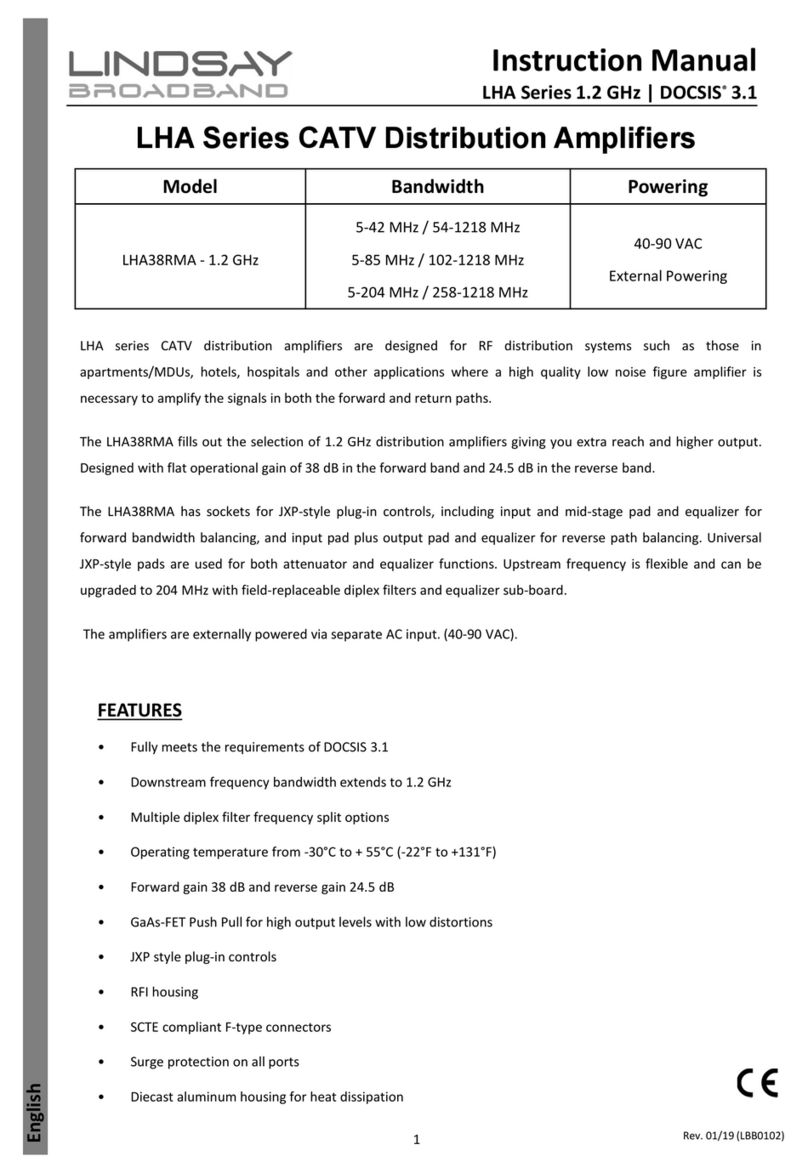
LA35Rx Series 1 GHz Compact MDU Amplifiers
Installation Manual
Page 1 of 4
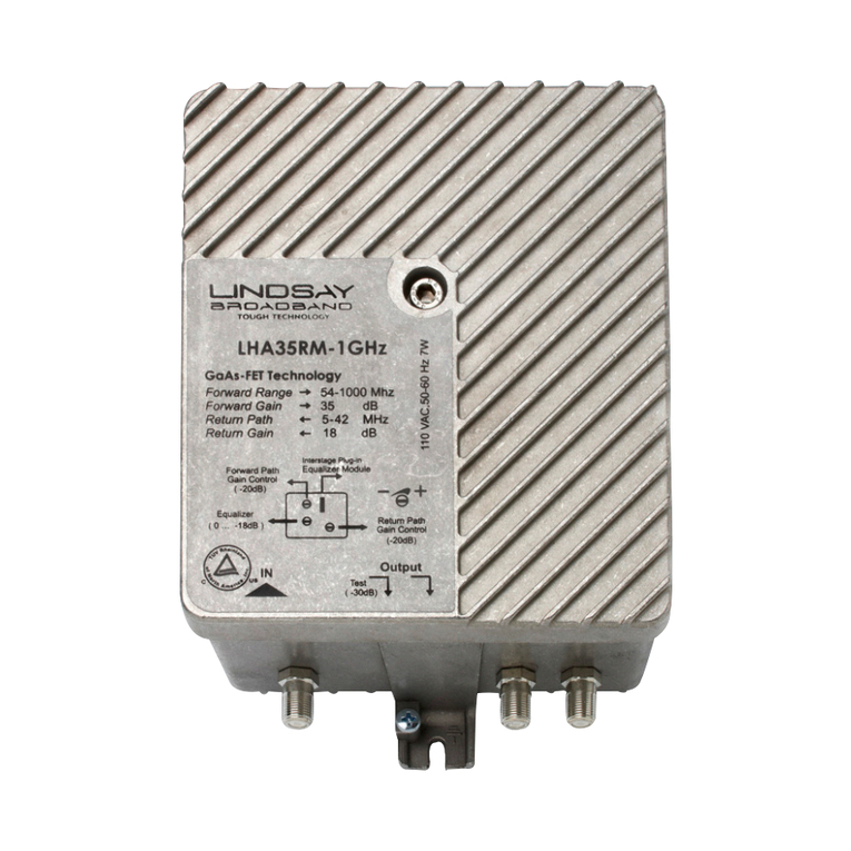
Lindsay Broadband’s LA35Rx compact, multiple-dwelling unit (MDU) broadband distribution amplifier is a full-featured, 2-way, 1 GHz indoor station wth superior
distortion characteristics and low noise.
It is a tough, indoor MDU amplifier specifically designed for broadband distribution systems in apartment buildings, hotels, schools, hospitals and other similar facilities
requiring RF amplification where high quality, low noise figure amplifiers are necessary in both forward and return paths.
Compact in size and designed to mount directly to a wall with increased heat dissipation and low power consumption, this amplifier runs cool and reduces operational
costs. GaAs E-pHEMT push-pull technology provides superior distortion performance and low noise to 1 GHz in both the forward and return paths. It has flat
operational gain of 35 dB in the forward path and 18 dB in the return path. This amplifier also has an input variable EQ and plug-in mid-stage equalization feature in the
forward bandwidth for balancing, a forward 20 dB input gain control, and 20 dB input and output reverse gain controls.
FEATURES
•Compact, aluminum diecast, wall-mountable housing
•Designed for superior heat dissipation
•GaAs E-pHEMT push-pull design for high output, low distortions & very high efficiency
•Active reverse bandwidth 5-42/5-65 MHz
•Forward gain 35 dB; reverse gain 18 dB
•JXP plug-in style mid-stage EQs (available 0-20 dB in 2 dB steps)
•Rated ingress protection IP54, against dust & water
•Operating Temperature: -30°C to +55°C (-22°F to +131°F)
•Maximum RFI shielding
•SCTE compliant F-type connectors
•-20 dB, bi-directional, external test points
•6 kV surge protection on all ports
•90-240 VAC universal powering
PRODUCT OVERVIEW
Part # Power Socket Type Frequency Range
LA35R 42/54 x x = 10-36 VDC 5-42 MHz / 54-1000 MHz
LA35R 65/85 x 5-65 MHz / 85-1000 MHz
LA35R 42/54 x x = 90-240 VAC 5-42 MHz / 54-1000 MHz
LA35R 65/85 x 5-65 MHz / 85-1000 MHz
CAUTION
Risk of electric shock. Do not open.
No serviceable parts inside. Refer servicing to qualified service personnel.
WARNING: To prevent shock hazard, do not expose this unit to rain or moisture. This apparatus shall not be exposed to dripping or splashing
water and no objects filled with liquids, such as vases, shall be placed on the apparatus.
WARNING: This product is a Class-I construction. Please ensure a connection to power source includes a protective earthing connection.
Remember to replace cover after adjusting. Cover must be in place for CE, safety and protection.
FUNCTIONAL SCHEMATIC

LA35Rx Series 1 GHz Compact MDU Amplifiers Installation Manual
Page 2 of 4
JXP mid-stage
equalizers
SPECIFICATIONS
Parameter Specification
Forward Reverse
Bandwidth 54-1000 MHz 5-42 MHz
85-1000 MHz 5-65 MHz
Technology GaAs E-pHEMT Si-bipolar
Full Gain (Average) 35 dB 18 dB
Flatness ± 1 dB
Return Loss In/Out -16 dB
Test Points In/Out -20 dB
Gain Control Variable 20 dB (In) 20 dB (In/Out)
Slope Control Input, Variable 0-20 dB
JXP Plug-in (Mid) 0-20 dB in 2 dB steps
Forward Distortions: 42 dBmV (54/1000 MHz) flat output level, 79 NTSC channels, digital at -6 dB after 550 MHz
CTB on CH 78 58 dBc
CSO on CH 78 -64 dBc
XMOD on CH 2 -60 dBc
Forward Distortions: 32/44 dBmV (54/1000 MHz) output level, 79 NTSC channels, digital at -6 dB after 550 MHz
CTB on CH 78 65 dBc
CSO on CH 78 65 dBc
XMOD on CH 2 65 dBc
Reverse Distortions: 48 dBmV flat output on each of CH T8 & T9 according to ANSI/SCTE1 152006
DTO on 7 & 25 MHz -75 dBc
DSO on 6 MHz on 6 & 32 MHz -60 dBc
XMOD on T10 on T8, T9 -75 dBc
Noise Figure with 0 dB Jumpers < 6 dB
Group Delay Forward (CH2) < 35 ns
Reverse (41-42 MHz) < 35 ns
Power, Environmental & Physical
Hum Modulation < -80 dBc
RFI Isolation -90 dBc
Surge Withstand In/Out IEEE C62.41-Cat A3, 6 kV, 200 A
Powering 10-36 VDC / 90-240 VAC
Power Consumption 4 W
Enclosure IP54 category, diecast aluminum
Operating Temperature -30°C to +55°C (-22°F to +131°F)
Dimensions (H x W x D) 5.2”H x 5.2”W x 2.0”D (13.0H x 13.0W x 5.1D cm)
Weight 1.6 lb (0.7 kg)
LA35R 42/54 VER 10-36V 1.0GHz
(front view)

LA35Rx Series 1 GHz Compact MDU Amplifiers Installation Manual
Page 3 of 4
NOTE TO CATV SYSTEM INSTALLER
This reminder is provided to call the CATV system installer’s attention to Article 820-40 of the NEC that provides guidelines for proper grounding and, in particular,
specifies that the cable ground shall be connected to the grounding system of the building, as close to the point of cable entry as practical.
INSTALLATION & FORWARD OUTPUT LEVEL SETUP GUIDELINES
1. Adjustable gain and cable slope controls are reachable under the housing lid. Refer to layout scheme above the RF circuit for controls adjustment.
2. This product is shipped with default 0 dB pad for plug-in interstage equalization.
3. Before applying power to the amplifier make sure that the input level to the amplifier is not too high or damage to the amplifier might occur. To be on the safe side,
you should set the input gain control adjustment to minimum gain (fully counterclockwise) before powering the amplifier.
4. Set the input equalizer control for minimum slope (fully clockwise) and install a 0 dB plug-in equalizer (factory-installed) into the mid-stage equalizer socket.
5. Now apply power to the amplifier and measure the amplifier output level at the 20 dB output test point. If it is very low then turn the input gain control clockwise to
increase the gain until the desired output level is reached at the highest operating frequency. Remember that the level measured at the test point is 20 dB lower
than the real signal level.
6. Turn the input equalizer control to adjust the forward output level to be flat across the full bandwidth. The input signal level will now be flat too. Under this condition
there will be best CNR across the full bandwidth.
7. Now install a plug-in equalizer into the mid-stage equalizer socket to get as close as possible to the desired output signal slope. The desired output slope is
determined by your system design. Consult your system planner or your system maps for this information. Equalizers are available in 2 dB steps from 0-20 dB at 1
GHz.
8. Make a final adjustment of the slope and output level with the input gain and slope controls. Always adjust the gain control, then the slope control in that order.
9. Remember to replace lid after adjusting.
INSTALLATION PRECAUTIONS TABLE
Precautions Requirement
Facilitate service and maintenance Allow a minimum of 35 in. (90 cm) clearance in front of the equipment rack(s)
Avoid direct heating or air conditioning If unavoidable, use deflector plates
AC power source outlets Locate equipment near sufficient outlets to provide power for test equipment and power tools
Rack support Make certain rack supports are sufficiently rigid to support rack(s)
Building leakage Beware of dripping water onto equipment from leaky roofs, waveguide roof entries, and cold water pipe condensations
SPECIFICATIONS (JXP-XX JXP-STYLE ATTENUATOR/EQ)
dB
Value
Parameter & Specification
Insertion Loss Typical Delta Return Loss
S21 @ 5 MHz S21 @ Full Band 5-1200 MHz 5-750 MHz 5-1000 MHz 5-1200 MHz
00 ± 0.15 dB ± 0.25 dB -0.1 dB 25 dB 19 dB 16 dB
01 ± 0.15 dB ± 0.30 dB -0.15 dB 26 dB 24 dB 20 dB
02 ± 0.15 dB ± 0.35 dB -0.2 dB 27 dB 24 dB 21 dB
03 ± 0.15 dB ± 0.35 dB -0.2 dB 25 dB 24 dB 20 dB
04 ± 0.15 dB ± 0.40 dB -0.25 dB 25 dB 24 dB 21 dB
05 ± 0.15 dB ± 0.40 dB -0.25 dB 25 dB 24 dB 20 dB
06 ± 0.15 dB ± 0.40 dB -0.25 dB 25 dB 24 dB 20 dB
07 ± 0.15 dB ± 0.40 dB -0.25 dB 25 dB 24 dB 20 dB
08 ± 0.15 dB ± 0.46 dB -0.3 dB 25 dB 23 dB 20 dB
09 ± 0.15 dB ± 0.46 dB -0.3 dB 25 dB 24 dB 20 dB
10 ± 0.15 dB ± 0.46 dB -0.3 dB 25 dB 24 dB 20 dB
1.2" (3.0 cm)
0.5" (1.3 cm)
0.2" (0.5 cm)
ORDERING INFORMATION
Part # Description
LA35R 42/54 VER 10-36V 1.0GHz 1 GHz, 2-way amplifier with 35 dB gain forward, 18 dB gain reverse, 42/54 MHz diplexer, 10-36 VDC
LA35R 65/85 VER 10-36V 1.0GHz 1 GHz, 2-way amplifier with 35 dB gain forward, 18 dB gain reverse, 65/85 MHz diplexer, 10-36 VDC
LA35R 42/54 VER 90-240V 1.0GHz 1 GHz, 2-way amplifier with 35 dB gain forward, 18 dB gain reverse, 42/54 MHz diplexer, 90-240 VAC
LA35R 65/85 VER 90-240V 1.0GHz 1 GHz, 2-way amplifier with 35 dB gain forward, 18 dB gain reverse, 65/85 MHz diplexer, 90-240 VAC
Required Accessory
6506-056 100-240 VAC/15 VDC wall transformer
Optional Accessories
JXP-xx JXP-style fixed attenuator/EQ (xx = dB value; available values = 00,01,02,03,04,05,06,07,08,09,10,11,12,13,14,15,16,17,18,19,20)

2-2035 Fisher Dr, Peterborough, ON K9J 6X6 Canada
+1.705.742.1350 • 1.800.465.7046 • support@lindsaybb.com • lindsaybb.com
© 2021 Lindsay Broadband Inc. All rights reserved. Printed in Canada. Non-Lindsay Broadband product marks,
service marks, and company names in this document are the property of their respective owners. All information is subject to change without notice.
Rev. 12/21 (LBB0413) • Page 4 of 4
LA35Rx Series 1 GHz Compact MDU Amplifiers Installation Manual
SPECIFICATIONS (JXP-XX JXP-STYLE ATTENUATOR/EQ) CONT'D.
dB
Value
Parameter & Specification
Insertion Loss Typical Delta Return Loss
S21 @ 5 MHz S21 @ Full Band 5-1200 MHz 5-750 MHz 5-1000 MHz 5-1200 MHz
11 ± 0.15 dB ± 0.46 dB -0.3 dB 25 dB 24 dB 20 dB
12 ± 0.15 dB ± 0.43 dB -0.27 dB 25 dB 22 dB 20 dB
13 ± 0.15 dB ± 0.45 dB -0.3 dB 25 dB 24 dB 20 dB
14 ± 0.15 dB ± 0.45 dB -0.3 dB 25 dB 24 dB 20 dB
15 ± 0.15 dB ± 0.46 dB -0.31 dB 25 dB 24 dB 20 dB
16 ± 0.15 dB ± 0.46 dB -0.31 dB 25 dB 26 dB 22 dB
17 ± 0.15 dB ± 0.43 dB -0.27 dB 25 dB 26 dB 22 dB
18 ± 0.15 dB ± 0.45 dB -0.3 dB 25 dB 26 dB 22 dB
19 ± 0.15 dB ± 0.45 dB -0.3 dB 25 dB 26 dB 22 dB
20 ± 0.15 dB ± 0.45 dB -0.3 dB 25 dB 28 dB 22 dB
NOTE:
JXP pads are applicable for both attenuator & equalizer (excluding forward input EQ) functions.
JXP-style are rectangular attenuators/pads with pins arranged inline (0.125" center to center
spacing). Pins are 0.038" in diameter. They can be inserted in two ways (flipped 180°) and provide
the same performance either way.
This manual suits for next models
2
Other Lindsay Broadband Amplifier manuals

