Unison Research Sinfonia User manual

HIGH - END ELECTRONICS BORN
IN ITALY
SINFONIA

2
INDEX
Index ............................................................ pag.2
Owners Manual ........................................... pag.3
Manuale di Istruzioni ................................... pag.11
Technical Characteristics ........................... pag.20
Declaration of Conformity ........................... pag.21

3
OWNERS MANUAL
First may we thank you for choosing a valve amplifier from
A.R.I.A. Advanced Research In Audio srl.
Your new amplifier is the result of many years of electronic
design experience allied to a thorough understanding of
electronic tubes. But more than that it is the fruit of our
passion, and of our wish to create products to give musical
enjoyment and lasting value, in which the traditional
craftsman’s skill is blended with advanced electronic design.
Each and very one of our products is built using the best and
most trusted materials, before being subjected to rigorous
testing and final inspection.
All the wood parts are hand made in solid wood by expert
craftsmen, and finished exclusively with natural organic
lacquers. As well giving a very pleasing appearance to the eye,
the wood also benefits sound quality by helping to dampen
resonance in the metal chassis .
UNPACKING
First of all please make sure that the carton is scaled and that
the amplifier has not suffered any damage in transit. If you
notice any signs of damage, consult your Authorised Dealer
before attempting to operate the unit.
To protect delicate parts against shocks during transport, valves
are normally packed separately.
Please refer to the fitting instructions for valves contained in
this manual .

4
IMPORTANT !
When unpacking an amplifier which is cold, allow it to
stand for sufficient time to reach normal room temperature
before attempting to operate it. This precaution will allow
any condensation which may have formed on the electronic
parts to fully dissipate.
Keep the original carton and packing material in a safe
place. You will need it if you have to send the unit for service
or transport it for any other reason.
VALVE FITTING
Fit the valves into their corresponding sockets following the
scheme you can see on the transformers covers and the
indications on the valves themselves which ensure the correct
orientation.
When fitting (or removing) valves, use firm but gentle
pressure. Never use force !
PLACEMENT
The unit should be placed on a safe, stable surface, out of
reach of children or pets. Adequate ventilation is required
above and around the unit. Take care not to expose the unit to
high temperature or humidity.

5
CONNECTING INPUTS AND OUTPUTS
Situated on the rear panel of the Sinfonia are the input and
output sockets.
IMPORTANT !
Ensure that all other items of equipment to be connected to
the amplifier are switched off before making the
connections.
Do not insert the amplifier AC mains cord until all input
and loudspeaker connections are securely made.
To avoid the possibility of hum and noise, it is good practice
to ensure that all connections to and from the amplifier are
clean and tight, and that all cable runs are neat and tidy.
For best results, AC mains cables should not be placed
alongside signal or loudspeaker cables.
Using RCA phono interconnects of suitable quality, connect
the various sources (CD, tuner, phono) to the corresponding
inputs of the amplifier.
On the rear panel of the unit is also located a power supply
plug for the unit Simply Phono by Unison Research.
The power supply circuit has fuses not accessible externally,
whose characteristics are listed at the end of this manual.
Remember when connecting the loudspeaker cables to the
amplifier output terminals to respect the correct phase (red =
+/black = -) for each channel. With the double loudspeaker
outputs provided on the Sinfonia it is possible to connect to
loudspeakers using bi-wiring, (provided of course that the
loudspeakers are fitted with two sets of input terminals). Note
that the upper and lower loudspeaker sets of output terminals of
6
the Sinfonia are in parallel, therefore either set may be used for
normal loudspeaker connection.
The Sinfonia is also equipped with a low-impedance
subwoofer output controlled by the volume potentiometer.
The circuitry of the Sinfonia is conceived to provide an
effective protection from short circuits which may occur at
the outputs.
CONNECTION TO MAINS
Before connecting the mains cable and switching on, make
sure that your local power supply voltage corresponds to the
value shown on the rear panel of the unit.
IMPORTANT !
Never connect the amplifier to a mains supply of a different
voltage to that shown on the unit !
Mains fuses are located in the IEC mains input socket
located on the rear of the unit. The correct value is indicated on
the rear panel and also in the technical specifications at the end
of this manual.
If you need to replace a mains fuse, always use one of the
same type and rating !
OPERATION
After switching on, the Sinfonia stands by for a time of
about 5 seconds, during which the four diodes on the front
panel are on and the outputs are disabled.

7
This time is necessary to allow the valves to stabilise and
reach the operating temperature. The optimal temperature,
corresponding to the best sound performance, is reached after
about 15 minutes from switching on.
After the initial warm up the outputs are enbled, the last
input used is selected and the corresponding led on the front
panel lights on.
The subwoofer output is enabled after 60 seconds.
VOLUME CONTROL
Before swithcing on the unit, ensure that the volume control
is at the minimum (fully anticlockwise) position.
During the initial warm up keep the volume at the minimum
to avoid any possible sollicitation due to transient effects.
After the warm up time it is possible to regulate the volume
either rotating the volume control handle on the front panel or
pushing the dedicated buttons on the remote handset.
IMPORTANT !
All the operations at the inputs or outputs should be
preferably executed when the device is switched off or
anyway keeping the volume at the minimum.
INPUT SELECTION
The desired input can be selected either rotating the input
selector handle on the front panel or from the remote control.
Inputs are activated in sequence; the one currently active is
identified be the corresponding led on the front panel switched
on.

8
In case you use the remote control, press the “Sel” button
until you reach the desired input (see remote control functions).
REMOTE CONTROL FUNCTIONS
Both volume and input selection of the amplifier can be
controlled by means of the InfraRed remote handset.
The remote control unit supplied with the Sinfonia is fully
compatible with the standard handset of the Unico series
amplifiers and the Unico CD.
IMPORTANT !
When using the wood remote control for the first time press
the learning button (marked by the Unison Research logo).
Every time you will use the standard handset, to switch
back to the wood remote control you will have to repeat
this operation.
This operation has always to be repeated after using the
standard handset to control the Sinfonia.
The remote handset is supplied with two AAA type batteries
(1.5V) which should be inserted into the handset by opening
the rear flap. Ensure that the correct polarity is respected when
fitting the batteries. Replacement batteries should be of the
same type.
SWITCHING OFF THE UNIT
After switching off the unit, wait around 5 minutes before
switching it on again. This time is necessary to allow the valves
to cool down to room temperature.

9
SAFETY AND MAINTENANCE
Do not open the amplifier !
High voltages are present inside. There are no user
serviceable parts inside, and all service operations should be
undertaken only by an Authorised Service Centre.
Please note that any service work or modification to the unit
carried out by unauthorised personnel may invalidate the
warranty. Refer any service queries in the first instance to your
Dealer.
Do not spill liquid into the amplifier.
If that should happen, switch off immediately and remove
the mains plug from the wall. Have the amplifier checked by an
Authorised Service Centre.
When inserting the mains plug into the wall socket or
mains outlet, make sure that the on/off switch on the unit is
in the off position.
If you do not intend to use the unit for a long period,
remove the mains plug from the mains supply.
Cleaning the amplifier
Cleaning the unit should take place only when it is switched
off and the valves are cold.
Use a soft dry cloth. Do not use solvents or alcohol based
detergents.
Do not rub hard when cleaning the printed lettering.
Never operate the unit if it is covered !
Never attempt to remove the valves when the unit is
switched on !

10
If you need to remove and replace the valves, do so only
when the valves are cold and the unit is switched off.
Replace valves only with others of the same type,
preferably in matched pairs.
Avoid shocks and vibration to the unit, which can damage
or reduce the life of the valves.

11
MANUALE D’ISTRUZIONI
Ci congratuliamo e Vi ringraziamo per la fiducia accordataci
per aver scelto un amplificatore valvolare A.R.I.A. Advanced
Research In Audio S.r.l..
La realizzazione di questo componente audio è sicuramente
il risultato di una lunga esperienza di progettazione e di una
profonda conoscenza dei tubi elettronici, ma è anche il frutto
della nostra passione e della nostra volontà di realizzare pezzi
“unici”, di grande valore, in cui la tradizionale abilità artigiana
si unisce e si integra con un’alta tecnologia elettronica.
Ogni nostro prodotto viene realizzato con materiali di
grande affidabilità e pregio e viene infine provato e testato in
modo scrupoloso.
Tutte le parti di legno, realizzate in massello da esperti
artigiani e trattate esclusivamente con prodotti naturali, oltre al
loro valore estetico, svolgono un’importante azione di
smorzamento della risonanza del telaio metallico.
SBALLAGGIO
Verificate innanzitutto che l’imballo sia integro e che
l’apparecchio non abbia subito danni evidenti durante il
trasporto: in tal caso vi raccomandiamo di consultare il vostro
rivenditore prima di mettere in funzione l’apparecchio.
Per migliorare la sicurezza dell’apparecchio durante il
trasporto e per contenere le dimensioni dell’imballo, è possibile
che alcune parti accessorie siano fornite smontate: in questo

12
caso vi raccomandiamo di attenervi alle istruzioni contenute
nel presente libretto per il montaggio.
IMPORTANTE !
Una volta che il Sinfonia è stato tolto dall’imballo, si
consiglia di attendere qualche ora prima di effettuarne la
connessione alla rete elettrica: l’eventuale presenza di
condensa potrebbe provocare infatti danni
all’amplificatore a causa della alte tensioni alle quali opera.
La condensa potrebbe formarsi anche in seguito allo
spostamento dell’amplificatore da un ambiente freddo ad
uno caldo: anche in questo occorre attendere che
l’amplificatore si sia adattato alla nuova temperatura
prima di poterlo utilizzare.
Conservate l’imballo intatto: vi servirà nel caso in cui
doveste riutilizzarlo, e contribuirete così alla tutela
dell'ambiente.
INSERIMENTO DEI TUBI ELETTRONICI
Sulle calotte di copertura dei trasformatori è indicata
schematicamente la posizione ed il modello di ciascuna
valvola.
Qualora sia necessario effettuarne il montaggio inizialmente
o per successive sostituzioni attenersi a tale schema inserendo
le valvole negli zoccoli corrispondenti, avendo cura di
rispettare la chiave di inserimento e le indicazioni riportate
sulle stesse.

13
INSTALLAZIONE
L’amplificatore integrato Sinfonia deve sempre essere
posizionato in un luogo sicuro e stabile, al di fuori della portata
dei bambini. E’ necessario assicurargli un’adeguata
ventilazione ed evitare di esporlo ad elevate temperature ed
umidità.
COLLEGAMENTO DEGLI INGRESSI
Connettete le sorgenti di segnale (lettore Compact Disc,
Tuner, Phono) agli ingressi RCA dedicati, posizionati sul
pannello posteriore del Sinfonia.
Sul pannello posteriore è presente anche una presa che
consente di alimentare l’unità Unison Research Simply Phono.
Il circuito alimentatore è provvisto di fusibili non
accessibili dall’esterno, le cui caratteristiche sono riportate tra
le specifiche tecniche alla fine di questo manuale.
COLLEGAMENTO DELLE USCITE
Collegate i cavi dei diffusori ai morsetti di uscita
dell’amplificatore, facendo attenzione a rispettarne la polarità
(rosso – nero).
La doppia morsetteria di uscita consente di collegare in
modalità bi-wiring diffusori che supportino tale tipo di
connessione. In condizioni normali le casse acustiche si
possono collegare indifferentemente ai connettori superiori o
inferiori, rispettando comunque la polarità (rosso – nero) ed i
canali (L/R).

14
Il Sinfonia è provvisto inoltre di un’uscita per subwoofer a
bassa impedenza controllata dal potenziometro del volume.
Il circuito del Sinfonia è studiato per garantire un’efficace
protezione da eventuali corto circuiti che possono
verificarsi alle uscite.
IMPORTANTE !
Il funzionamento stesso dello stadio di uscita valvolare
rende sconsigliabile l’utilizzo dell’amplificatore se i
diffusori non sono collegati.
COLLEGAMENTO ALLA RETE.
Prima di accendere il Sinfonia, controllate che la tensione di
alimentazione posta sul retro corrisponda a quella locale di
rete.
IMPORTANTE !
Non collegare mai l’amplificatore ad una tensione di rete
diversa da quella indicata!
I fusibili di rete si trovano nel portafusibile incorporato nella
presa IEC. Il loro valore corretto è indicato sul retro
dell’apparecchio e tra le specifiche tecniche riportate alla fine
di questo manuale.
Sostituire i fusibili sempre con altri dello stesso tipo e
valore!

15
ACCENSIONE
All’accensione il Sinfonia necessita di un tempo di
riscaldamento di circa 5 secondi, durante il quale i quattro
diodi posizionati sul pannello frontale lampeggiano lentamente
e le uscite non sono attive.
Tale fase di preaccensione è necessaria per consentire alle
valvole di raggiungere la temperatura di funzionamento. La
temperatura ottimale, alla quale corrispondono i migliori
risultati sonori, viene raggiunta dopo circa 15 minuti
dall’accensione.
Dopo la fase di preaccensione vengono abilitate le uscite e
viene selezionato l’ultimo ingresso utilizzato, identificato dal
led corrispondente illuminato sul pannello frontale.
L’uscita subwoofer si attiva dopo circa 60 secondi.
REGOLAZIONE VOLUME
Prima di accendere l’apparecchio, assicurarsi che la
manopola del volume sul pannello frontale sia posizionata al
minimo. Durante la preaccensione si raccomanda di mantenerla
al minimo per evitare sollecitazioni inutili dovute a fenomeni
transitori.
Al termine del conteggio è possibile regolare il volume
ruotando delicatamente la manopola di regolazione presente sul
pannello frontale, oppure utilizzando i tasti appositi del
telecomando.
IMPORTANTE !

16
Tutti gli interventi agli ingressi e/o alle uscite vanno
effettuati preferibilmente ad apparecchio spento. In caso
contrario assicurarsi che il volume sia al minimo.
SELEZIONE DELL’ INGRESSO
L’ingresso desiderato può essere selezionato utilizzando la
manopola di selezione sul pannello frontale oppure da
telecomando. L’ingresso selezionato è identificato
dall’accensione del led corrispondente sul pannello frontale.
La rotazione della manopola comanda tramite
microprocessore la commutazione dei relè sigillati in atmosfera
inerte con contatti in oro che attivano l’ingresso desiderato.
Gli ingressi vengono selezionati in successione ruotando la
manopola in senso orario o antiorario.
Se si utilizza il telecomando, premere ripetutamente il tasto
“Sel” fino a che il led corrispondente all’ingresso desiderato è
acceso (vedi paragrafo telecomando).
TELECOMANDO
La regolazione del volume e la selezione degli ingressi
dell’amplificatore possono essere effettuati utilizzando il
telecomando IR fornito in dotazione all’amplificatore e già
provvisto di batterie.
Il telecomando in legno dell’amplificatore Sinfonia è
compatibile con il telecomando standard in dotazione agli
amplificatori della serie Unico e Unico CD.

17
IMPORTANTE !
La prima volta che si utilizza il telecomando in legno in
dotazione al Sinfonia è necessario premere il tasto di
apprendimento contraddistinto dal logo Unison Research.
In seguito, ogni volta che verrà utilizzato il telecomando
standard, per tornare all’uso del telecomando in legno
occorrerà ripetere tale operazione.
Sostituire sempre le batterie del telecomando con batterie
dello stesso tipo, avendo cura di rispettarne la polarità.
SPEGNIMENTO
Dopo aver spento il Sinfonia occorre attendere circa 5
minuti prima di poterlo accendere nuovamente. Questo tempo è
necessario per consentire alle valvole di riportarsi a
temperatura ambiente.
Se l’amplificatore venisse acceso mentre le valvole sono
ancora calde, infatti, si avrebbe un assorbimento di corrente
immediato. Ciò sarebbe considerato una situazione di
funzionamento anomalo da parte del sistema automatico di
protezione degli alimentatori stabilizzati interni, che
interverrebbe immediatamente bloccando il normale
funzionamento dell’amplificatore.

18
PRECAUZIONI DI SICUREZZA E
MANUTENZIONE
Non aprire l’apparecchio.
Nessun intervento oltre a quelli descritti in questo manuale
deve essere effettuato dall’utente.
Per l’assistenza rivolgersi al proprio rivenditore o ad un
centro autorizzato.
La non osservanza delle suddette indicazioni comporta
l’immediata decadenza della garanzia.
Non versare liquidi sull’apparecchio.
Se ciò dovesse accadere, togliere immediatamente la spina
dalla presa a muro e portare l’apparecchio ad un centro
assistenza autorizzato.
Prima di inserire la spina nella presa a muro, assicurarsi
che l’interruttore sia nella posizione “OFF”.
Nel caso il Sinfonia non venga utilizzato per lunghi periodi,
si raccomanda di staccare la spina dalla presa di rete.
Non utilizzare mai l’apparecchio coperto.
Non rimuovere le valvole con l’apparecchio in funzione, o
quando sono ancora calde.
Colpi o vibrazioni sono dannosi per la valvole.
Sostituire le valvole esclusivamente con altre dello stesso
tipo, possibilmente selezionate.
Pulizia dell’apparecchio.
La pulizia del Sinfonia va eseguita ad apparecchio spento e con
le valvole fredde.
Utilizzare un panno morbido ed asciutto. Non usare solventi
o detergenti a base di alcool. Non strofinare sulle scritte
energicamente.

19
TECHNICAL CHARACTERISTICS
Type: all-valve integrated amplifier
Valve complement: 4 x KT88, 2 x ECC82, 2 x ECC83
Operating Mode: Pure Class A
Power stage: Parallel single-ended ultralinear
Output power: 27 Watt/channel
Bandwidth: 20 – 30000 Hz
Remote control: volume – inputs IR
Output impedance: 4 Ohm and 8 Ohm
Input impedance: 47 kOhm
Inputs: 4 linea, 1 tape
Outputs: 1 tape, 1 subwoofer
Consumption: 500 watt
Dimensions : 40cm x 38,5cm x 19,5cm
15,7 x 15,1 x 7,6 inches
Net weight: 25 kg 50 Ibs
Fuses: 5x20 – 6.3 A T 100V to 120V
5x20 – 3.15 A T 220V to 240V
Phono Power Supply (internal):
5x20 – 1AT e 5x20 – 500mA T
A.R.I.A. Advanced Research In Audio s.r.l. reserves the option of
incorporating design refinements and/or modifications into existing product
lines without notice or obligation.Unison Researchis registered trade name
of A.R.I.A. Advanced Research In Audio s.r.l.

20
DECLARATION OF CONFORMITY
for
Sinfonia
Amplifier
Manufacturer
A.R.I.A. Advanced Research In Audio srl
Via E. Barone, 4
31010 Dosson di Casier (TV)
ITALY
Statement of Conformity
Based on test results using appropriate standards, the product is in conformity with
Electromagnetic Compatibility Directive 89/336/EEC
92/31/EEC
93/68/EEC
Low Voltage Directive 73/23/EEC
93/68/EEC
Sample test
Standard used:
EN 55013-1 : 1993 (and subsequent modifications)
Limits and methods of measurement of radio disturbance
characteristics of broadcast receivers and associated equipment
EN 61000-3-2 : 1995 (and subsequent modifications)
Electromagnetic compatibility. Part3: Limits – Section 2: Limits for
harmonic current emissions (equipment input current ≤16A per
phase)
EN 61000-3-3 : 1995 (and subsequent modifications)
Electromagnetic compatibility. Part3: Limits – Section 2: Limitation
of voltage fluctations and flicker in low-voltage supply systems for
equipment with rated current ≤16A
EN 60335; EN 61305-1; EN 61305-3; CEI 84-2; CEI 84-3; CEI 84-8.
The tests have been performed in a typical configuration.
This Conformity is indicated by the symbol , i.e. « Conformité européenne ».
This manual suits for next models
2
Table of contents
Languages:
Other Unison Research Amplifier manuals

Unison Research
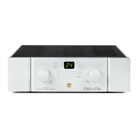
Unison Research Unico Due User manual

Unison Research
Unison Research REFERENCE PRE User manual

Unison Research
Unison Research C5P User manual

Unison Research
Unison Research Unico 90 User manual

Unison Research
Unison Research P30K User manual

Unison Research
Unison Research SH User manual

Unison Research
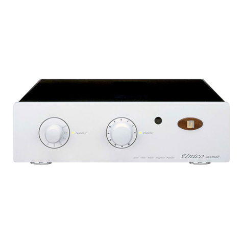
Unison Research Unico Secondo User manual

Unison Research
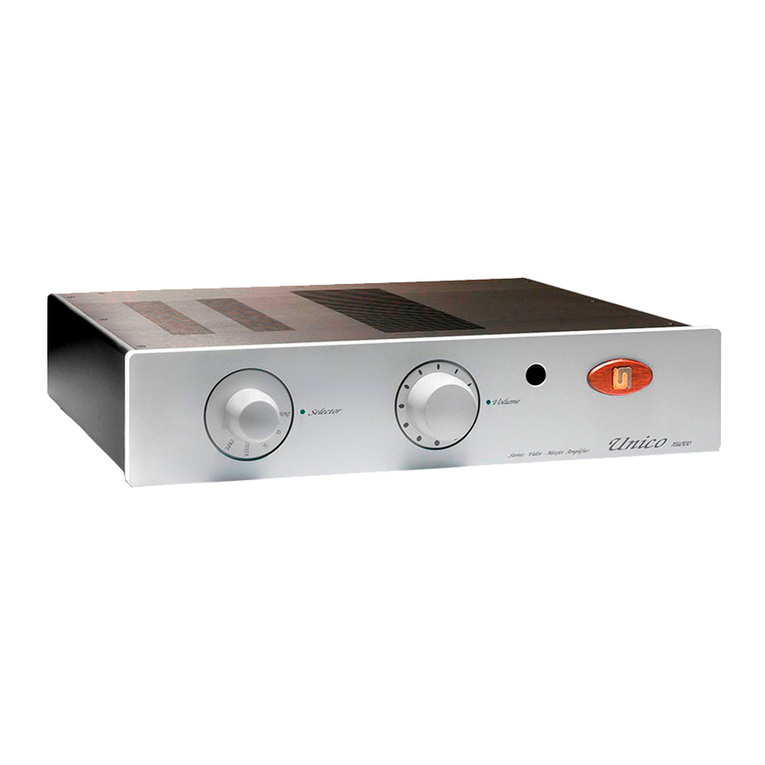
Unison Research Unico Nuovo User manual