Lindsay Broadband LB-1000-RR User manual

Aug 01 2019
LB-1000-RR
Headend Platform Quad Return Receiver
User Manual

2-2035 Fisher Dr., Peterborough, ON CANADA K9J 6X6 Ph: (705) 742-1350 or (800) 465-7046 Email: support@lindsaybb.com
ii
LB-1000-RR
User Manual
TABLE OF CONTENTS
TABLE OF CONTENTS ................................................................................................................ii
1.0 PRODUCT OVERVIEW AND FEATURES....................................................................... 1
1.1 Description...................................................................................................................... 1
1.2 Features .......................................................................................................................... 1
1.3 Specifications ................................................................................................................. 2
1.4 Block diagram of the LB-1000-RR .............................................................................. 3
2.0 SAFETY NOTES................................................................................................................. 4
3.0 APPLICATION MODULE DESCRIPTION....................................................................... 5
4.0 INSTALLATION ................................................................................................................. 6
5.0 LB-1000-RR SETTINGS..................................................................................................... 8
5.1 LB-1000-RR settings: Using touch screen ................................................................ 8
5.2 LB-1000-RR settings: Using Web interface............................................................. 10
6.0 WARRANTY AND RMA POLICY .................................................................................. 12

2-2035 Fisher Dr., Peterborough, ON CANADA K9J 6X6 Ph: (705) 742-1350 or (800) 465-7046 Email: support@lindsaybb.com
1 | P a g e
LB-1000-RR
User Manual
1.0 PRODUCT OVERVIEW AND FEATURES
1.1 Description
Lindsay Broadband LB-1000-RR series is a family of CATV Return Path Receiver Module,
converting upstream optical signal into RF signal at the headend or remote hubs. LB-1000-RR
return receiver incorporates a low noise PIN detector and RF amplifier chain. Internal selectable
RF attenuators can be switched in or out to enable each receiver to handle a very wide range of
optical input signals. Module parameters can be monitored and configured through the LB-1000-
CM system management module using the touch screen or by using the PC (Web GUI or SNMP
agent).
1.2 Features
•Four independent return path receivers in a single module
•Hot-swappable capability
•Bandwidth 5~205 MHz
•-18 to +1dBm: Standard RRx Input Range; -27 to -13dBm: RFoG RRx Input Range
•Optical AGC and MGC mode for Standard RRx, Only MGC mode for RFoG RRx
•High Output level (30dBmV) with low noise
•RF output disabled automatically when no optical signal detected, and each independent
channel can also be disabled manually using LB-1000-CM
•Manual attenuation control for each RF port
•RF output test point
•Can monitor and configure functioning parameters using LB-1000-CM

2-2035 Fisher Dr., Peterborough, ON CANADA K9J 6X6 Ph: (705) 742-1350 or (800) 465-7046 Email: support@lindsaybb.com
2 | P a g e
LB-1000-RR
User Manual
1.3 Specifications
PARAMETER
SPECIFICATION
UNIT
NOTE
Optical Performance
Wavelength
1290 to 1620
nm
Input Power
-18 to +1
dBm
Standard version
-27 to -13
dBm
RFoG version
Optical AGC
-18 to +1
dBm
Standard version only; No AGC in
RFoG version
Optical Return Loss
> 45
dB
Number of Receivers
4
Connector
SC/APC
RF Performance
Bandwidth
5 –205
MHz
Return Loss
≥16
dB
Flatness
± 0.75
dB
Output Level
30
dBmV
-18 dBm Rx in, 35% OMI
RF Output control
Yes
Using electronic attenuation
Impedance
75
Ω
Connector
F-female
Test point
- 20 ± 1
dB
Relative to RF port
Link Performance fiber (20 kms) + Attenuator, 13dB Link loss, Receive power -10 dBm, 37 MHz loading
NPR
≥ 40
dB
Electrical / Physical Performance
Power Consumption
< 20
W
From Backplane of LB-1000-CH
Dimensions
442 D x 22 W x 119 H
mm
Weight
0.8
Kg
2-2035 Fisher Dr., Peterborough, ON CANADA K9J 6X6 Ph: (705) 742-1350 or (800) 465-7046 Email: support@lindsaybb.com
3 | P a g e
LB-1000-RR
User Manual
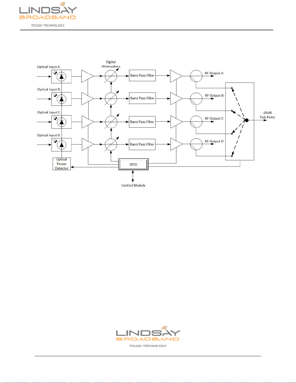
1.4 Block diagram of the LB-1000-RR
Figure 1: Block diagram of the LB-1000-RR Quad Return Receiver
2-2035 Fisher Dr., Peterborough, ON CANADA K9J 6X6 Ph: (705) 742-1350 or (800) 465-7046 Email: support@lindsaybb.com
4 | P a g e
LB-1000-RR
User Manual
2.0 SAFETY NOTES
Failure to comply with these safety precautions and with the general or specific safety precautions
described elsewhere in the LB-1000 series manual violates the safety standards of the design,
manufacture, and intended use of the device. Lindsay Broadband Inc. assumes no liability for the
customer’s failure to comply with these precautions.
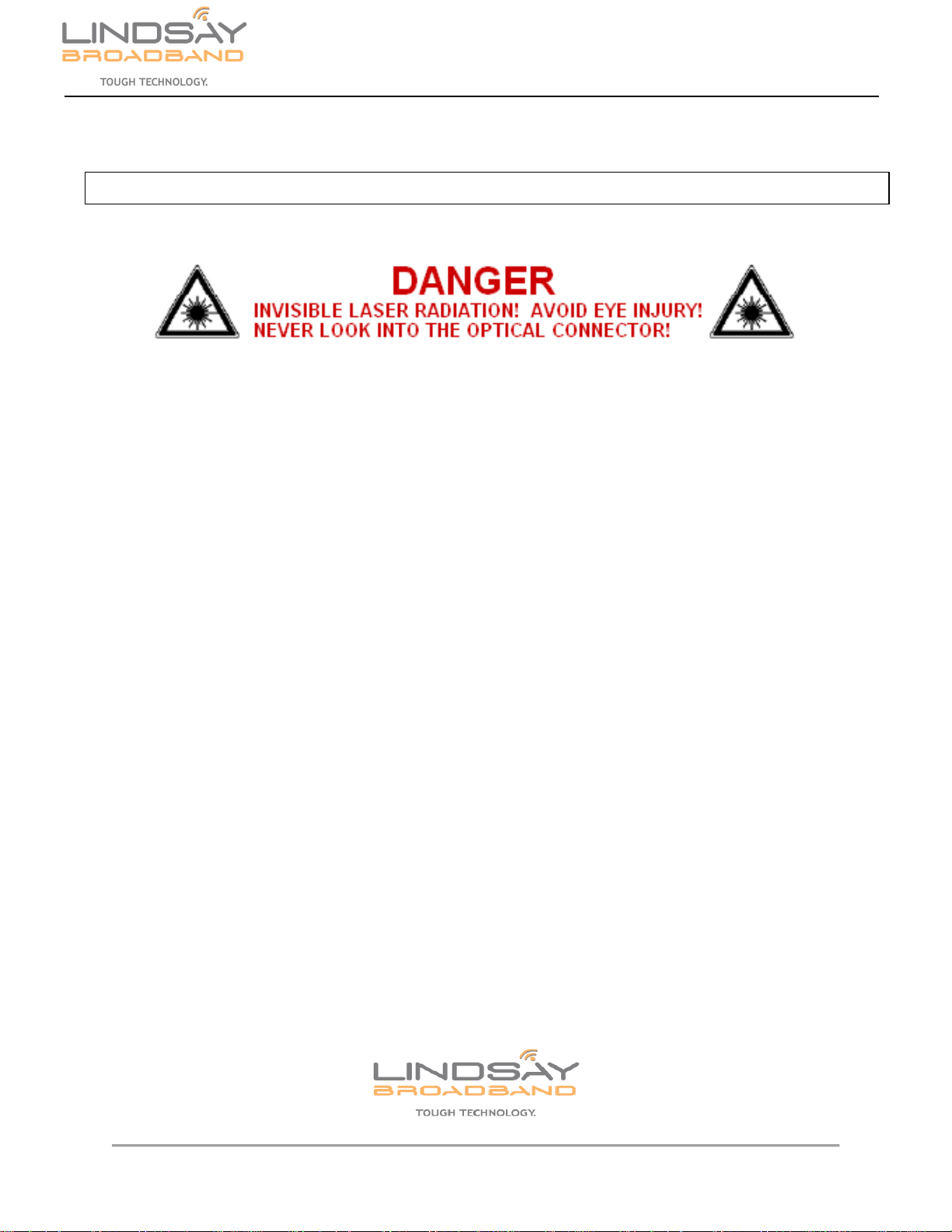
•Invisible optical radiation is emitted from fiber optic connectors which connects to this LB-
1000-RR, exposure can cause permanent injury to eyes.
•Avoid direct exposure to the laser light source.
•Never stare directly into a fiber or at any mirror-like surface that could reflect light emitted
from an un-terminated fiber.
•Never view an active fiber through optical instruments.
CAUTION: To avoid damaging the touchscreen LCD, please do not tap it with anything sharp or
apply excessive pressure to it with your fingertips. It is recommended to use fingers when using
the touch screen LCD.
CAUTION: Do not operate the chassis outside of its maximum ratings. Doing so may result in
unsatisfactory performance, unit failure, shortened unit life span, or a safety hazard.
NO SERVICEABLE PARTS INSIDE. REFER SERVICING TO QUALIFIED SERVICE PERSONNEL.

2-2035 Fisher Dr., Peterborough, ON CANADA K9J 6X6 Ph: (705) 742-1350 or (800) 465-7046 Email: support@lindsaybb.com
5 | P a g e
LB-1000-RR
User Manual
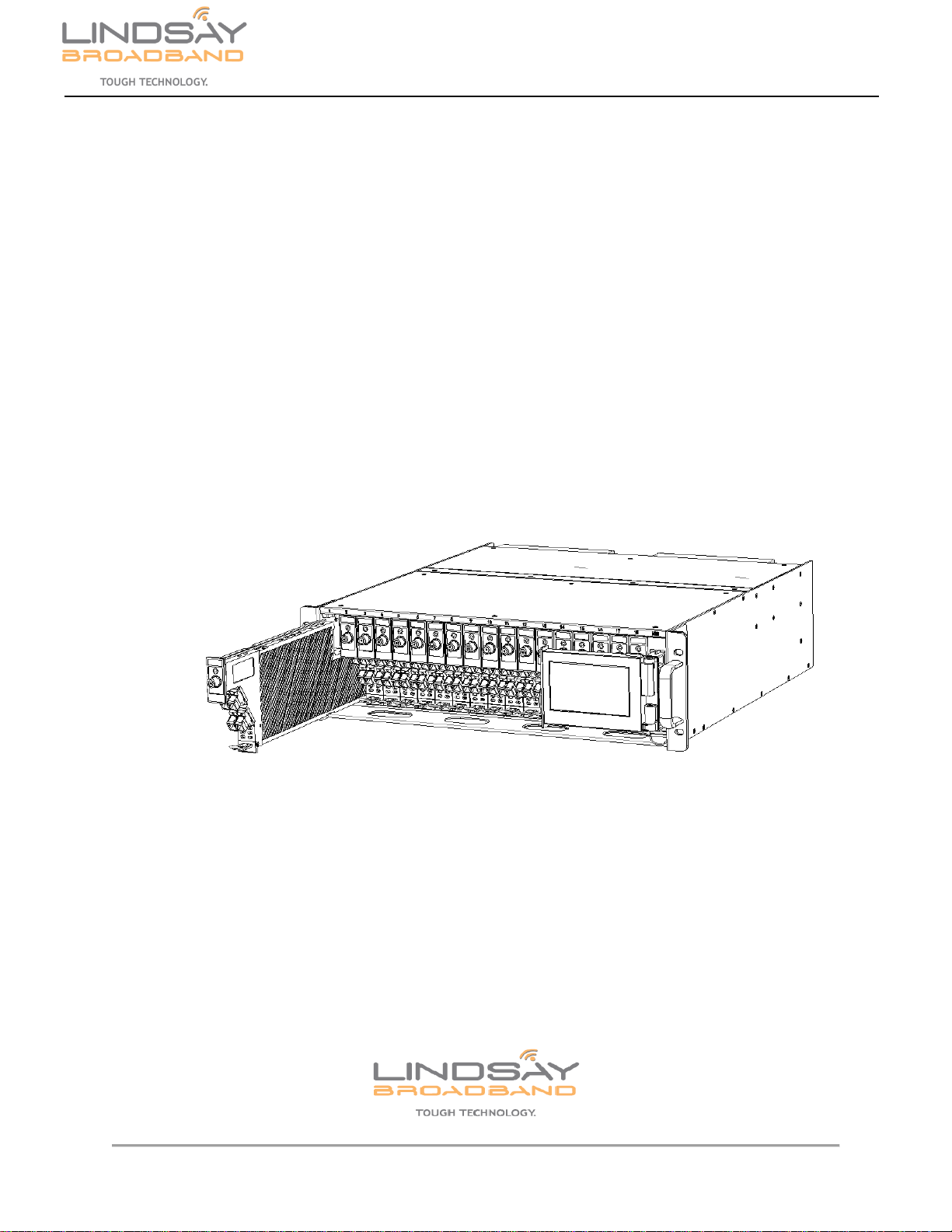
3.0 APPLICATION MODULE DESCRIPTION
Figure 2: LB-1000-RR Front and Rear Panel
Front Panel:
1. Status LED will be green when the Return receiver module is operating normally and will
be red when there is an alarm.
2. The Test Point is a -20dB TP relative to the output port.
3. Module Handle to draw the application module in/out.
4. Optical Inputs: A, B, C and D
5. Latch to secure the module.
Rear Panel:
6. PIN CONNECTOR for DC power and signals to the chassis backplane
7. F-type female port for RF output from the return receiver. Ports A, B, C and D.
2-2035 Fisher Dr., Peterborough, ON CANADA K9J 6X6 Ph: (705) 742-1350 or (800) 465-7046 Email: support@lindsaybb.com
6 | P a g e
LB-1000-RR
User Manual
4.0 INSTALLATION
Application modules of LB-1000 can be installed in any of the general slots of the rack. Module is
inserted into the rack from the front part.
1) Gently insert the LB-1000 application module into any general slot (labelled 01 to 18)
from the front of the chassis. Be careful to align the metal guide rails on the top and
bottom of the module to the chassis housing.
2) Using the handle completely push the application module into the slot. Once the
module is completely inserted into the slot, the latch on the bottom of the module will
lock into place with the LB-1000 chassis securing the module in the rack. Ensure that
the application module is securely connected to the LB-1000-CH rear panel and F-
connectors. The application module will be automatically power “ON”. The Status LED
on the front of the module will turn ON and the module will show up on the control
module screen or web interface.
Figure 3: LB-1000 application module installation
3) If the module hasn’t been properly connected to the LB-1000-CH it will not power up
and status LED will be OFF. In such a case, remove the application module from LB-
1000-CH slot and reinsert carefully as described in steps 1 and 2 above. See below
step for safely removing the module.
4) To remove the application module from the slot, press down on the latch located in the
bottom front of the module. The application module will unlock from the LB-1000-CH
rack and the module can be removed.

2-2035 Fisher Dr., Peterborough, ON CANADA K9J 6X6 Ph: (705) 742-1350 or (800) 465-7046 Email: support@lindsaybb.com
7 | P a g e
LB-1000-RR
User Manual
5) Connect the RF cable to the appropriate RF output connectors on the rear panel of
the LB-1000-CH.
6) Carefully clean all the fiber optic connectors and jumper cables. Use appropriate
cleaning swabs for fiber optic cables and connectors. Check for contamination/blemish
on the fiber cable and connector with a fiber inspecting microscope. Ensure the fiber
optic connectors and jumper cables are clean.
7) Ensure optical jumper connectors are matched properly to the device adapters. (i.e.
SC/APC to SC/APC). Using mismatched connectors will damage the connectors and
degrade system performance. Ensure that each fiber has a matching connector.
8) Use an optical power meter to verify that the optical input power level to the receiver
is within the specification (-18 to +1dBm for Standard receiver; or -27 to -13dBm for
RFoG receiver). Connect the Optical fiber to the OPT IN connector on the front panel.
9) Using the touch screen or web interface via LB-1000-CM the operating parameters for
the application module can be monitored and adjusted. Operating parameters and
adjustments on the LB-1000-RR are explained in Section 5.
2-2035 Fisher Dr., Peterborough, ON CANADA K9J 6X6 Ph: (705) 742-1350 or (800) 465-7046 Email: support@lindsaybb.com
8 | P a g e
LB-1000-RR
User Manual
5.0 LB-1000-RR SETTINGS
Once the LB-1000-RR module is successfully connected, powered up and operating normally,
you will be able to see the corresponding slot populated with the module on the screen and on
the web interface of the LB-1000-CM system management module.
5.1 LB-1000-RR settings: Using touch screen
On the home screen of the LB-1000-CM touch screen, tap/touch the corresponding application
module slot (01-18) where the LB-1000-RR is plugged in. The selected application module will be
highlighted and the screen will show settings for the LB-1000-RR return receiver.
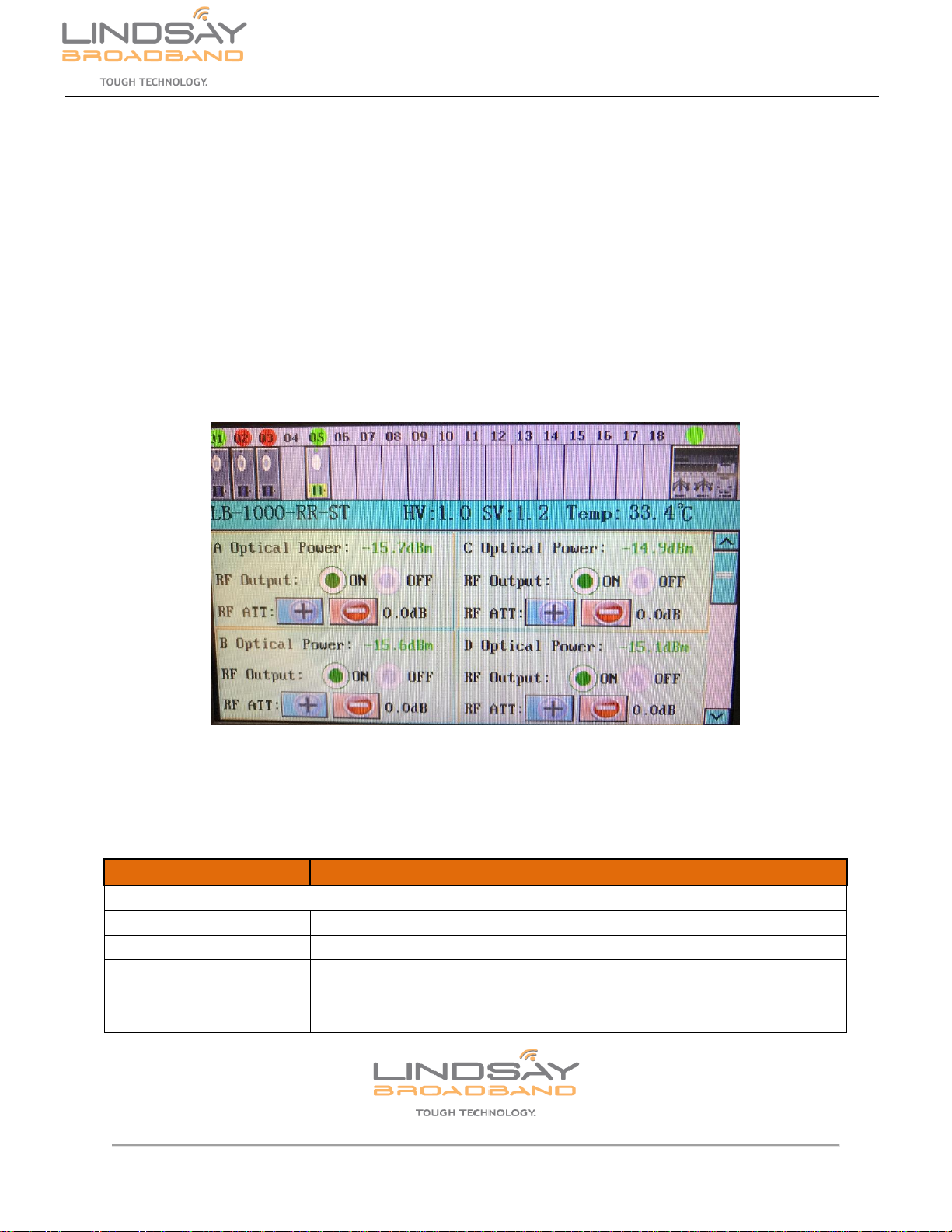
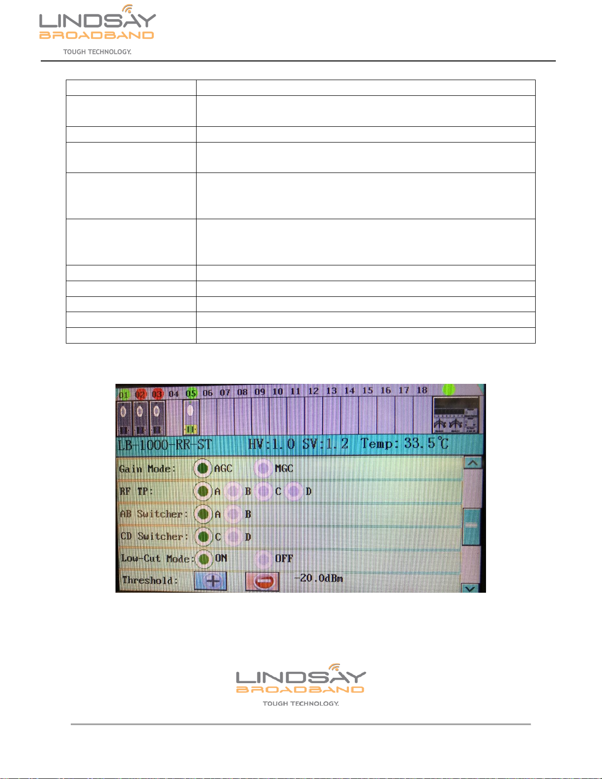
Figure 4: LB-1000-RR settings - Page 1
If a parameter indicates an alarm it will be displayed in red font. No alarm, the parameter will be
displayed in green font.
PARAMETERS
DESCRIPTION
LB-1000-RR
A / B / C / D Optical Power
Displays the Input Optical power for each of the channels
RF Output ON / OFF
Turn the unused RF Output channel ON/OFF
RF ATT
RF Output control using electronic attenuation. Min value under AGC: 0dB;
Max value under AGC: 31dB; Min value under MGC: 0dB; Max value under
MGC: 62dB
2-2035 Fisher Dr., Peterborough, ON CANADA K9J 6X6 Ph: (705) 742-1350 or (800) 465-7046 Email: support@lindsaybb.com
9 | P a g e
LB-1000-RR
User Manual
Laser Temperature
Shows the laser temperature (°C)
Gain Mode AGC / MGC
Select Automatic or Manual Gain Control mode for the receiver. Only in
Standard version of RRx. RFoG version of RRx is only MGC mode.
RF TP A / B / C / D
Select RF Output Test Point for one of the four channels
AB / CD Switcher
For special functional module only, special order. Not a standard feature
of the return receiver. Select main channel for back up operating mode.
Low-Cut Mode ON / OFF
Enable or Disable optical protection mode. Optical/RF channel turned OFF
when optical power below a certain level. Only for Standard version. This
setting is not available in RFoG version of RRx.
Threshold + / -
Set Optical threshold level for Low-Cut Mode. Min value: -21dBm; Max
value: -14dBm. Only for Standard version. This setting is not available in
RFoG version of RRx.
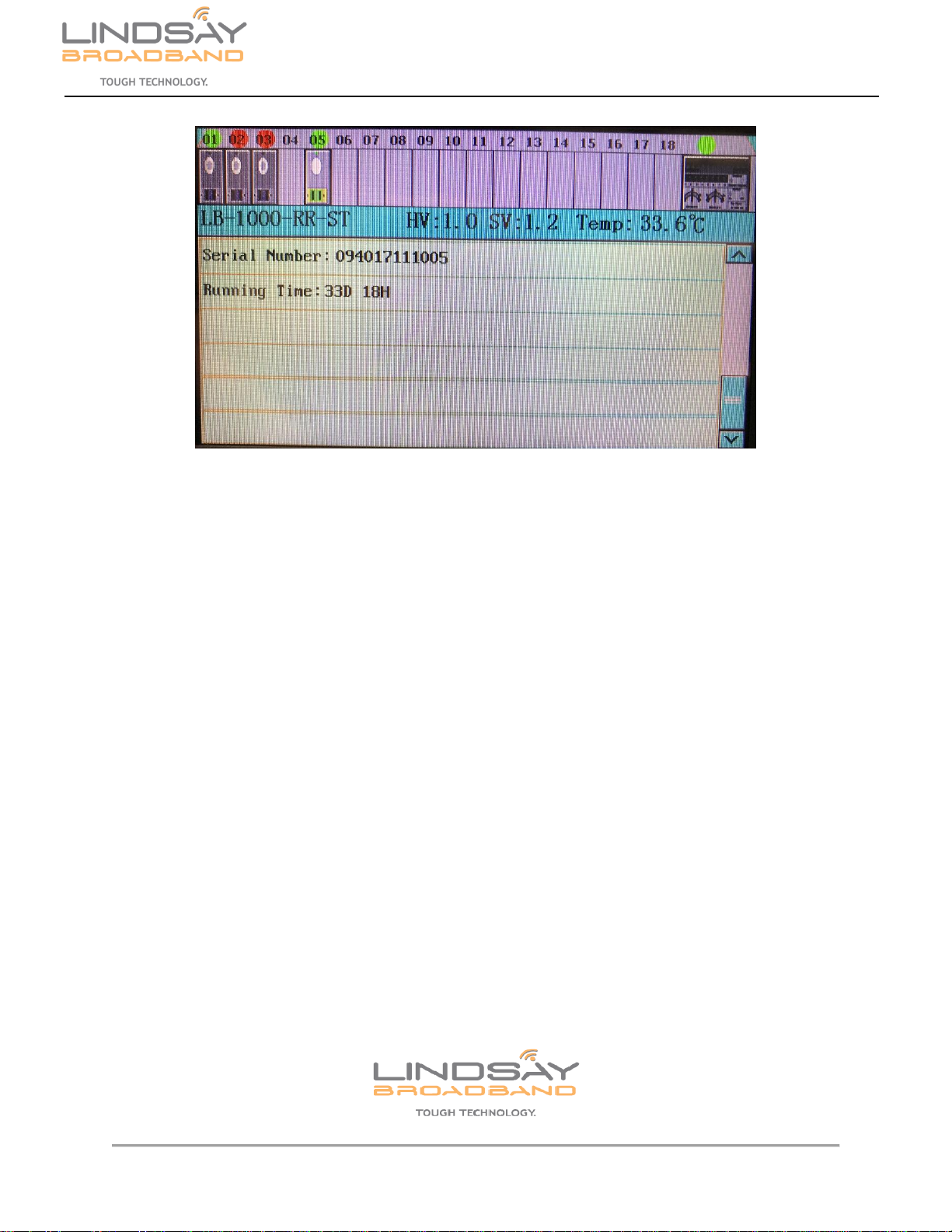
Serial Number
Shows the module serial number
Hardware Version
Shows the hardware version
Firmware Version
Shows the firmware version
Temperature
Shows the current module temperature (°C)
Running Time
Shows the active run time of the module
Figure 5: LB-1000-RR settings - Page 2
2-2035 Fisher Dr., Peterborough, ON CANADA K9J 6X6 Ph: (705) 742-1350 or (800) 465-7046 Email: support@lindsaybb.com
10 | P a g e
LB-1000-RR
User Manual
Figure 6: LB-1000-RR settings - Page 3
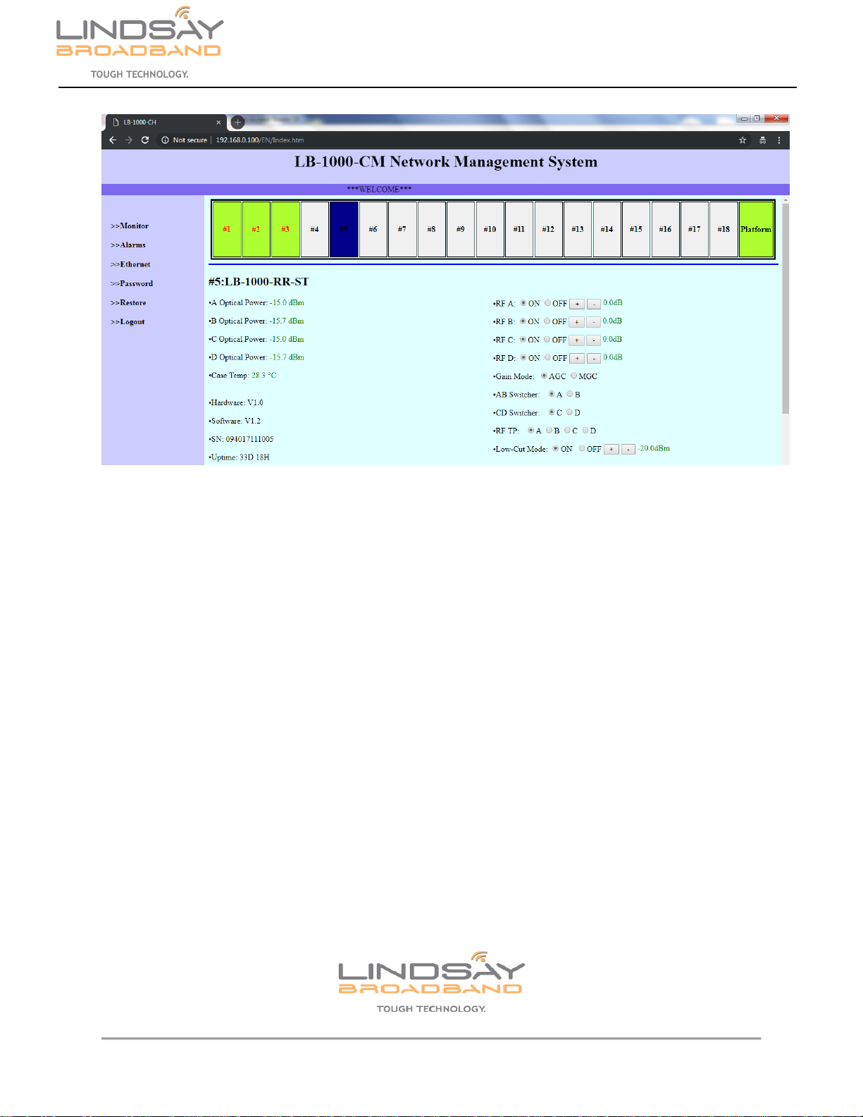
5.2 LB-1000-RR settings: Using Web interface
Refer to LB-1000-CM manual. Connect your computer to the LB-1000-CM using the RJ-45 LAN
port. Login to the LB-1000-CM Web interface.
On the home screen of the LB-1000-CM Web interface, click the corresponding application
module slot (#1 - #18) where the LB-1000-RR is plugged in. The selected application module will
be highlighted and the screen will show settings for the LB-1000-RR return receiver.
User can monitor parameters and modify the configurable parameters of the LB-1000-RR module
in this interface. Press +/- buttons to modify the parameters.
If the application module parameter has an alarm it will be displayed in red font. If no alarm, the
parameter will be displayed in green font. Click the “Alarms” option on the left hand side of the
screen to see the Alarm list. Find alarm information for corresponding slot number and module
from alarm list.
2-2035 Fisher Dr., Peterborough, ON CANADA K9J 6X6 Ph: (705) 742-1350 or (800) 465-7046 Email: support@lindsaybb.com
11 | P a g e
LB-1000-RR
User Manual
Figure 7: LB-1000-RR Web Interface
2-2035 Fisher Dr., Peterborough, ON CANADA K9J 6X6 Ph: (705) 742-1350 or (800) 465-7046 Email: support@lindsaybb.com
12 | P a g e
LB-1000-RR
User Manual
6.0 WARRANTY AND RMA POLICY
2-2035 Fisher Dr., Peterborough, ON CANADA K9J 6X6 Ph: (705) 742-1350 or (800) 465-7046 Email: support@lindsaybb.com
13 | P a g e
LB-1000-RR
User Manual
Lindsay Broadband Return Material Authorization Policy
Send your returns to:
Lindsay Broadband Inc.
2035-2 Fisher Dr.
Peterborough, ON Canada K9J 6X6
Attn: Product Returns
All shipments are to be pre-paid by the sender. No COD’s will be accepted.
A Return Material Authorization (RMA) Number is Required On all Product Returns
(Regardless if Product is Being Returned to Repair or credit)
Product Received at the Lindsay Broadband Factory
Without an RMA Number will be Returned to Sender
RMA number must be used when returning product for credit or repair. Use of RMA numbers
will ensure efficient processing. When returning product to Lindsay Broadband, please follow the
simple steps below (in the order that they appear):
RETURNS
1. Fill out the Product Return Authorization Form indicating product information. Repair items do not require original invoice
information, but it is helpful to determine warranty eligibility.
2. Contact Lindsay Broadband Inc. Service Department in one of three ways:
•E-mail to: [email protected] (recommended method) Include all of the information from the product
Authorization Form, or,
•Fax the Product Authorization Form to 1-705-742-7669 or,
•Call Lindsay Broadband Inc. @ 800-465-7046 Ext 235 / 261
3. After completing Steps 1 & 2, an RMA number will be assigned to you.
4. Securely pack the product and mark the box with your RMA #. If shipping multiple boxes, all boxes should be marked with
the RMA #. The RMA # must be placed near your return address in large, bold print (approximately 2” in height). Please see
the address label below as an example of the relative size location of the RMA #.
Sample Address label with RMA #
John Smith
ABC Company RMA 1234
123 Smith Street
Anytown, USA 00000
Lindsay Broadband Inc
2035 Fisher Dr.,
Peterborough, ON K9J 6X6
Attn: PRODUCT RETURNS
2-2035 Fisher Dr., Peterborough, ON CANADA K9J 6X6 Ph: (705) 742-1350 or (800) 465-7046 Email: support@lindsaybb.com
14 | P a g e
LB-1000-RR
User Manual
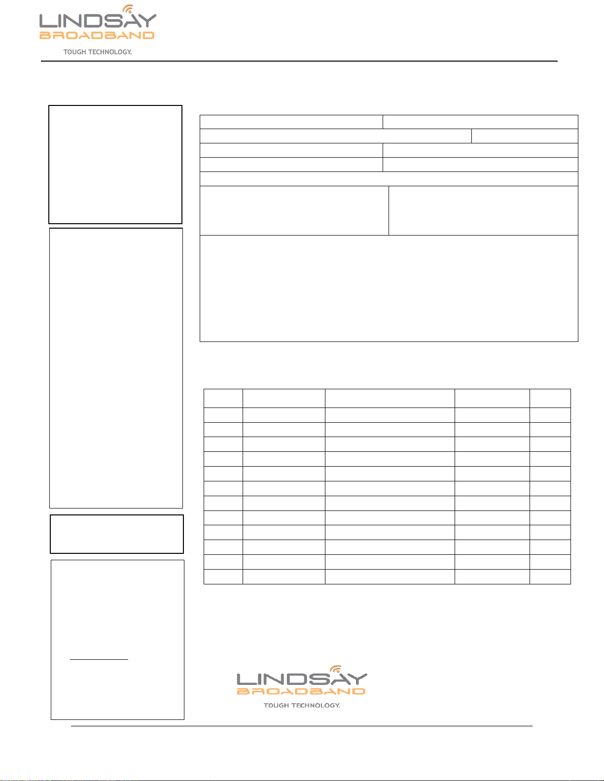
Lindsay Broadband Return Material Authorization (RMA) Form
Company
Contact Name:
Address:
City:
Prov/State:
Postal Code/Zip:
Phone: #:
Fax #:
Email address (if applicable)
RMA #
(To be supplied by Lindsay Broadband)
Date: ___________
Reason for return
Qty.
LBI Part #
Description
P.O. #
P.O.
Date
Service Repair Policy
Lindsay Broadband product may be
returned for repair under the following
condition:
1. Please contact Lindsay Broadband
Service Dept. to obtain an RMA#.
2. Please supply requested
information to verify 2warranty
coverage.
Any shipments received by Lindsay
Broadband without an RMA # will be
refused.
Credit Return Policy
Lindsay Broadband products may be
retuned for credit under the following
conditions:
1. Products are unused and
undamaged.
2. Products are accompanied by a one
dollar (new purchase) for one
dollar (credit return) order.
3. Products were purchased within
one year from credit return date
and are in a current catalog.
4. Products are subject to a 10% per
RMA and $2.00 per line item.
5. Products that are custom made are
subject to an additional charge for
conversion of not less than 20%
and not more than 50% of the FFP
price.
6. Product that require factory
repacking are subject to an
additional charge for material and
labour.
7. Please contact Lindsay Broadband
Customer Service to obtain an
RMA#.
Any shipments received by
Lindsay Broadband without
an RMA# will be refused.
Note: Products that are judged by
Lindsay Broadband Inc. upon receipt as
being unacceptable for credit shall be
returned to sender at their expense.
SHIPPING INSTRUCTIONS
1. Make Sure to Obtain an RMA# and
mark a box(s) accordingly
2. Ship Only Items Authorized
3. Enclose Packing Slip & Product
Return Authorization Form
4. Ship Prepaid Only to :
Lindsay Broadband Inc
2035-2 Fisher Dr.
Peterborough, ON CANADA
K9J 6X6
Attn: Product Returns
Table of contents
Other Lindsay Broadband Receiver manuals


