Link 2620 User manual

System 2600
2620 Sensor
Interface
Installation and Operating
Manual
Doc # L-2600-1020
Rev. 01
Link Electric & Safety Control Co.
444 McNally Drive
Nashville, TN 37211
Phone: (615) 833-4168
Fax: (615) 834-1984
© 2019


Doc #: L-2600-1020 Page 1 Rev. 01
Table of Contents
1INTRODUCTION .............................................................................................................................. 3
1.1 Features ........................................................................................................................................ 3
1.2 Specifications ............................................................................................................................... 4
2INSTALLATION ............................................................................................................................... 5
2.1 Wiring........................................................................................................................................... 6
2.1.1 Power Wiring ...................................................................................................................... 6
2.1.2 Internal Sensor Connector Wiring ...................................................................................... 7
2.1.3 Front Panel Sensor Connectors........................................................................................... 8
2.1.4 Wiring to the Die Protection Unit....................................................................................... 8

Doc #: L-2600-1020 Page 2 Rev. 01
Table of Figures
Figure 1: 2620 Sensor Interface .................................................................................................................. 3
Figure 2: 2620 Sensor Interface Dimensions.............................................................................................. 5
Figure 3: 2620 Sensor Interface Internal Features...................................................................................... 6
Figure 4: Typical Wiring to Internal Sensor Connector ............................................................................. 7
Figure 5: Typical Wiring to M12 Connector .............................................................................................. 8
Figure 6: Outputs Connector....................................................................................................................... 8

Doc #: L-2600-1020 Page 3 Rev. 01
1INTRODUCTION
The 2620 Sensor Interface unit permits
convenient connection of all kinds of sensor types
to die protection logic units such as OmniLink
MPC controls, System 2600 die protection units,
or even third party units. Sensors and probes
installed in or near the die are connected to the
Sensor Interface which also provides sensor
power
.
The Sensor Interface is designed to be located
near the die to facilitate die changes, setup, and
troubleshooting. It permits quick connection of
individual sensors via industry standard M12 4
pin connectors (also known as Micro-DC or
Eurofast connectors) or of all sensors at once via
an optional Quick Connect Receptacle (Link or
customer supplied).
1.1 Features
•Solid state sensors (NPN or PNP), spring probes, and mechanical sensors may be used as inputs to
the Sensor Interface.
•Up to 8 sensors can be powered and passed through to a die protection unit via the internal
connectors (usually through a Link or customer supplied bulk quick connection).
•6 M12 4 pin sensor connectors (also known as Micro-DC or Eurofast connectors) are provided on
the face of the unit for connecting individual sensors to channels 1 - 6.
•3 Banana plug/binding post connectors are provided on the face of the unit for connecting grounding
spring probes or mechanical sensors to channels 1 - 3.
•No configuration is necessary to select sensor type. This Sensor Interface is designed for die
protections units that can select NPN or PNP sensors on their own and so passes the sensor signal
directly through.
•The Sensor Interface is powered from 115 to 230 VAC and provides 24 VDC @ 0.5 Amp total for
powering sensors. Sensor power is available on each of the front panel M12 connectors, the optional
bulkhead connector, and internal terminal strips.
•In cases where 0.5 Amps is not enough power, the Sensor Interface can be powered by an external
24VDC power supply up to 10 amps.
•The enclosure of the Sensor Interface features a removable bulkhead that can be fitted with a quick
connection receptacle so that only one cable must be plugged in from the die. Link has an optional
standard connector (a 19 pin Turck receptacle suitable for up to 16 channels) or, if desired, a
customer supplied connector can be used.
MODEL 2620
SENSOR INTERFACE
POWER
LINK ELECTRIC & SAFETY CONTROL CO.
444 McNALLY DR. NASHVILLE, TN. 37211
PHONE (615) 833-4168
1 2 3
4 5 6
Figure 1: 2620 Sensor Interface

Doc #: L-2600-1020 Page 4 Rev. 01
1.2 Specifications
Size: 6.6” X 6.6” X 4.25” deep (Not counting connections on the front or quick
connect bulkhead connector)
Input Power: 90-264VAC, 47-63Hz, 0.4Amps
OR
24VDC +/- 10%, Up to 10 Amps
Sensor Power: 24 VDC 0.5 Amps total for all sensors from internal supply
24 VDC up to 10 Amps pass-through from external supply
Total Sensor Channels: 8
Front Panel Connections: 3 Banana plug/Binding Post (channels 1 - 3)
6 M12 4-pin (channels 1 - 6)
Internal Connections: Pluggable terminal strips (channels 1 - 8)
NOTE: Unit should be powered by AC power OR DC
power, Not Both!
Doc #: L-2600-1020 Page 5 Rev. 01
2INSTALLATION
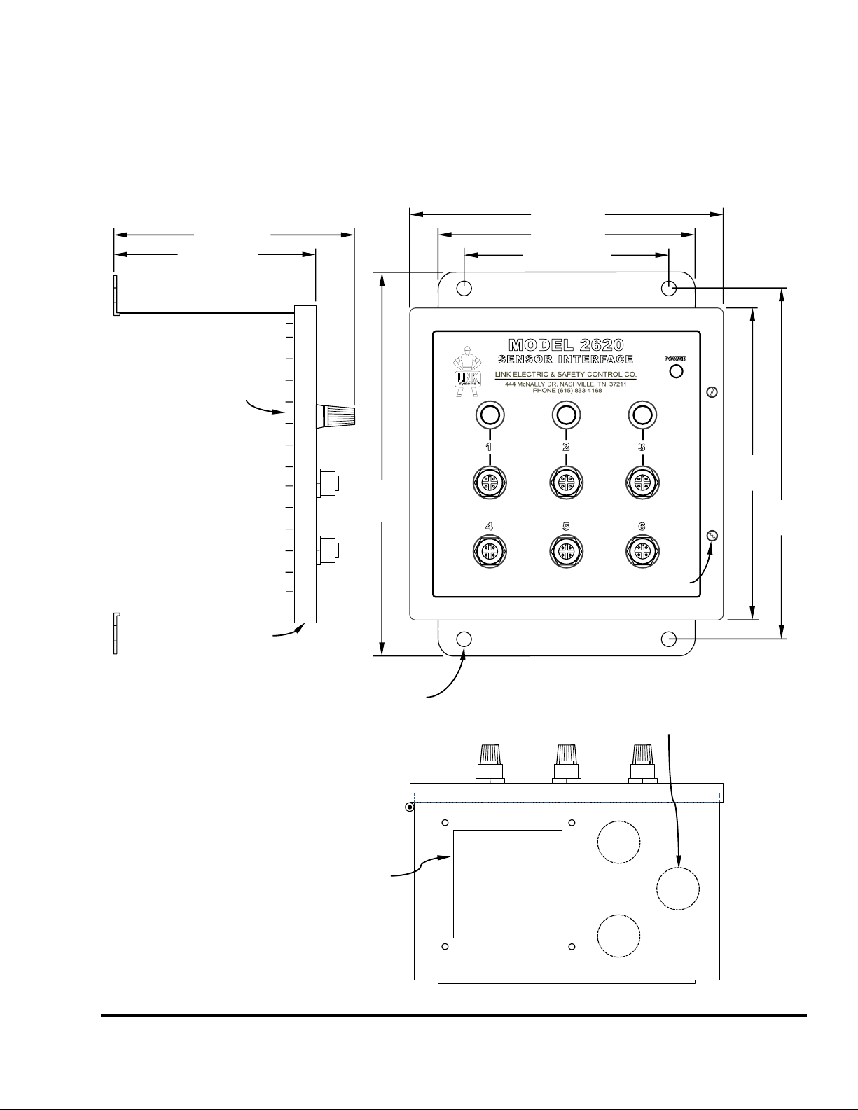
The dimensions and mounting footprint of the Sensor Interface are shown below in Figure 2. When
mounted to the press frame or other high shock areas, Link highly recommends using the included
shock mounts, which will add about 0.75 inches (19mm) to the depth of the unit.
6.6” (167)
0.31” (7.9)
diameter
(4 places)
4.25” (108)
5.4” (137)
6.6”
(167)
7.25”
(184)
8”
(203)
4.25” (108)
5.3” (135)
Door
Values in parentheses
are in millimeters
Hinge
Door Screws
(2 places)
2.25” (57)
Square Opening
for Quick Connect
(Plate Provided)
0.875” (22)
diameter
knockout
(3 places)
Figure 2: 2620 Sensor Interface Dimensions

Doc #: L-2600-1020 Page 6 Rev. 01
2.1 Wiring
In the following sections, refer to Figure 3below for the locations of particular connectors and other
relevant features.
2.1.1 Power Wiring
WARNING:
National Codes and standards (NEC, VDE, BSI, etc.) and local codes
outline provisions for safely installing electrical equipment.
Installation must comply with specifications regarding wire types,
conductor sizes, branch circuit protection, and disconnect devices.
Failure to do so may result in personal injury and/or equipment
damage.
The Sensor Interface is typically powered by 115VAC, but can be powered from 100 to 240 VAC OR
can pass through an external 24 VDC supply at up to 10 Amps. An external +24 VDC power supply
might be used in cases where unusually high power draw sensors require more than the 0.5 Amps of
current that is available from the internal power supply of the Sensor Interface. Pull power wires with
the appropriate color code in conduit between the Sensor Interface enclosure and the source of power.
Knockouts are provided at the bottom of the enclosure for this purpose.
Power Supply
WARNING
Hazardous Voltage
Contact may cause
Injury or death.
Remove power
Before servicing.
L1
L2
PE
+24
GND
REMOVE JUMPER
IF USING EXTERNAL
+24 VDC SUPPLY
O1 O2 O3 O4 O5 O6 O7 O8 NC GND
TOP ROW: OUT TO DIE PRO. UNIT
I1 I2 I3 I4 I5 I6 I7 I8 +24 GND
BOTTOM ROW: SENSOR CONNECTIONS
O1
O2
O3
O4
O5
O6
O7
O8
NC
GND
I1
I2
I3
I4
I5
I6
I7
I8
+24
GND
TURN THE CORRESPONDING
SWITCH ON FOR CHANNELS
USING BANANA PLUGS OR PIN
2 OF THE M12 CONNECTORS
CONNECTED TO “WHISKER”
SENSORS OR SPRING PROBES
1 2 3 4
Whisker Probe
Switches
Internal
Sensor
Connector
Outputs to
Die Pro. Unit
Connector Power
Connector
Power
Jumper
Figure 3: 2620 Sensor Interface Internal Features
Doc #: L-2600-1020 Page 7 Rev. 01
When using AC power, use the L1, L2 and PE
terminals. When using an external +24 VDC power
supply, use the +24, GND, and PE terminals. The
table at right shows the usage and specifications of
the connections on the power connector.
WARNING:
The Sensor Interface can be powered from EITHER 100-240VAC OR
+24VDC. Never hook up both AC and DC power at the same time.
When using an external +24 VDC supply, make sure the Power
Jumper (see Figure 3) is removed so that the internal +24 VDC supply
is disconnected.
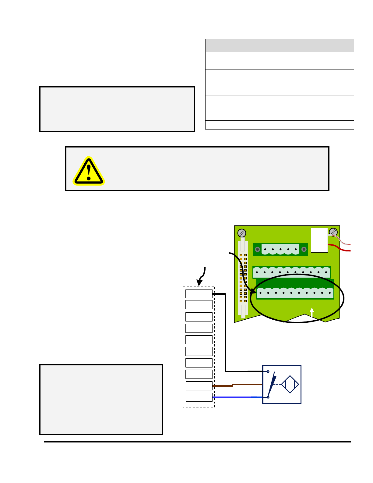
2.1.2 Internal Sensor Connector Wiring
The Internal Sensor Connector (see Figure
3) is primarily used in conjunction with a
Quick Connect bulkhead connector for
mass die termination or if there are some
sensors that are always present on the
machine regardless of what die is
installed. Link offers (Link PN 109090)
an optional quick connect bulkhead
connector (using a Turck CS-19
connector) that is prewired and ready to
plug into the Internal Sensor Connector.
Figure 4 at right shows how a typical
sensor is wired into this connector. The
unit is supplied with a blank plate for
mounting an existing connector if a
connector system is already in use.
Power Connector (See Figure 3)
L1
90 – 264 VAC Line
29 VA (0.4 Amp at 90 VAC)
L2
100 – 240 VAC Neutral
PE
Protective Earth (used with both AC
and DC input power)
+24
+24 VDC Input Power
(Up to 10 Amps can be passed
through)
GND
Ground - +24VDC Return
NOTE: When using an externa +24 VDC
supply, the Power Jumper (see
Figure 3) must be removed. This
disconnects the internal +24 VDC
supply of the Sensor interface.
L1
L2
PE
+24
GND
O1
O2
O3
O4
O5
O6
O7
O8
NC
GND
I1
I2
I3
I4
I5
I6
I7
I8
+24
GND
Internal
Sensor
Connector
1
6
4
5
2
3
7
8
I1
I6
I4
I5
I2
I3
I7
I8
9
10
+24
GND
NPN
BN
BU
NPN
Proximity
Sensor
BK
Figure 4: Typical Wiring to Internal Sensor Connector
NOTE: If a Quick Connect bulk
connector is wired into this
connector but there are
inputs that are not actually
connected in the die, then
the corresponding front
panel connectors are still
available for use.
Doc #: L-2600-1020 Page 8 Rev. 01
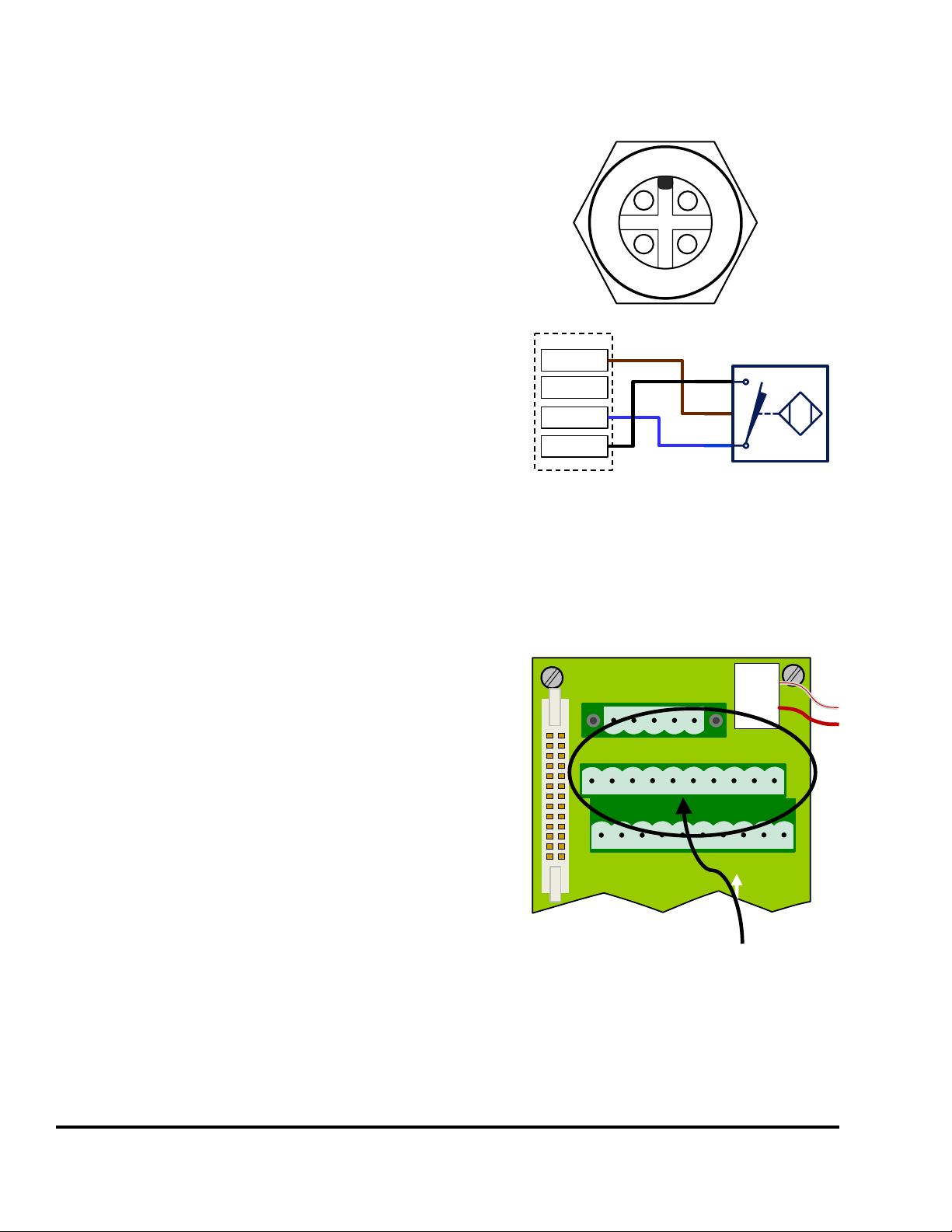
2.1.3 Front Panel Sensor Connectors
There are 6 M12 4-pin connectors on the front of Sensor
Interface that allow individual sensor to be conveniently
plugged in. These are wired to match the typical industry
standard 2 or 3 wire DC sensors with molded M12
connectors. M12 connectors are also available (Link PN
108046) that can be wired in the field. Figure 5 at right
shows the pinout and typical connection for the M12
connector.
There are also 3 Banana Plug/Binding Post connectors on the
front of the Sensor Interface that are intended for use with
single wire grounding sensors such as Whisker Probes,
Spring Probes, or other mechanical sensors that are
grounding in nature. Note that Pin 2 on the first 4 of the M12
connectors (labeled WP for “Whisker Probe”) is also a
grounding-only input so that such sensors can be tied in that
way as well. For these sensors, it may be necessary to source
more current through the sensor than is required with solid
state sensors in order to maintain good electrical contact. The grounding inputs have extra pull-ups for
this purpose and even more current can be supplied by switching on the corresponding dip switch for
that channel on the door board of the unit (see “Whisker Probe Switches” in Figure 3).
2.1.4 Wiring to the Die Protection Unit
Figure 6 at right shows a close-up of the outputs connector
that must be wired to the Die Protection Unit. Depending on
the number of channels your Die Protection Unit can handle,
it may not be necessary to use all the outputs. Always
connect the ground (“GND” in the figure at right) on the
outputs connector to ground on the Die Protection Unit.
Then O1 through O8 (or however many are needed) can be
connected to the corresponding Die Protection Unit input.
12
34
1
4
2
3
+24
Inp
WP
GND
NPN
BN
BU
NPN
Proximity
Sensor
BK
M12
Figure 5: Typical Wiring to M12
Connector
L1
L2
PE
+24
GND
O1
O2
O3
O4
O5
O6
O7
O8
NC
GND
I1
I2
I3
I4
I5
I6
I7
I8
+24
GND
Outputs to
Die Pro. Unit
Connector
Figure 6: Outputs Connector
Table of contents
Popular Recording Equipment manuals by other brands

RCS AUDIO-SYSTEMS
RCS AUDIO-SYSTEMS TIF-404 A operating instructions

Lexicon
Lexicon 960L - ADDENDUM LOGIC7 UPMIX ALGORITHM... manual

Actia
Actia PassThru+ XS 2G Getting started

Philips
Philips LFH 9750/00 Service manual

Pioneer
Pioneer DC-777Z operating instructions

HHB
HHB BurnIT CDR-830 operating instructions


