MDT BE-02001.01 User manual

MDT technologies GmbH • 51766 Engelskirchen • Papiermühle 1
1
10/2017
Technical Manual
MDT Universal Interfaces
BE –02001.01
BE –04001.01
BE –06001.01

Technical Manual Universal Interface BE
MDT technologies GmbH • 51766 Engelskirchen • Papiermühle 1
2
1 Content
1 Content................................................................................................................................................. 2
2 Overview............................................................................................................................................. 4
2.1 Overview devices........................................................................................................................... 4
2.2 Exemplary circuit diagrams .......................................................................................................... 4
2.3 Usage & areas of use ..................................................................................................................... 6
2.4 Structure & Handling..................................................................................................................... 6
2.5 Functions ....................................................................................................................................... 7
2.5.1 Overview functions................................................................................................................. 8
2.6 Settings at the ETS-Software ......................................................................................................... 9
2.7 Starting up ..................................................................................................................................... 9
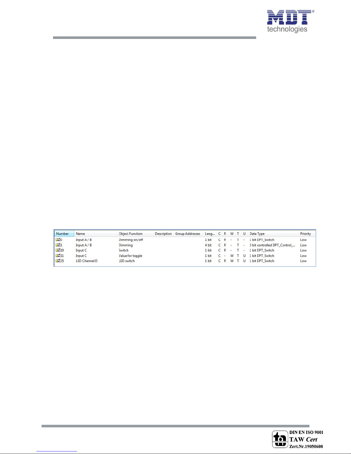
3 Communication objects.................................................................................................................... 10
3.1 Communication objects per channel ......................................................................................... 10
3.2 Communication objects logic ...................................................................................................... 12
3.3 Default settings of the communication objects .......................................................................... 13
4 Reference ETS-Parameter .................................................................................................................. 14
4.1 General Settings .......................................................................................................................... 14
4.2 Configuration............................................................................................................................... 16
4.3 Identical parameter..................................................................................................................... 17
4.3.1 Blocking object ..................................................................................................................... 17
4.4 Parameter Channels grouped...................................................................................................... 17
4.4.1 Dimming ............................................................................................................................... 18
4.4.2 Shutter.................................................................................................................................. 20
4.4.3 Switch ................................................................................................................................... 21
4.5 Parameters channels unique....................................................................................................... 22
4.5.1 Switch ................................................................................................................................... 22
4.5.2 Scene .................................................................................................................................... 32
4.5.3 Counter................................................................................................................................. 34
4.5.4 Switch short/long ................................................................................................................. 36
4.5.5 One button Dimming............................................................................................................ 39
4.5.6 One-button Shutter.............................................................................................................. 40
4.5.7 LED Output ........................................................................................................................... 41
4.6. Logic............................................................................................................................................ 42
4.6.1 Logic object type switch ....................................................................................................... 44
4.6.2 Logic object type scene ........................................................................................................ 46
4.6.3 Logic object type byte value................................................................................................. 46

Technical Manual Universal Interface BE
MDT technologies GmbH • 51766 Engelskirchen • Papiermühle 1
3
5 Index ................................................................................................................................................... 47
5.1 Register of illustrations................................................................................................................ 47
5.2 List of tables................................................................................................................................. 48
6 Attachment......................................................................................................................................... 49
6.1 Statutory requirements............................................................................................................... 49
6.2 Routine disposal .......................................................................................................................... 49
6.3 Assemblage.................................................................................................................................. 49
6.4 4-Bit Dim command..................................................................................................................... 50
6.5 Datasheet .................................................................................................................................... 51

Technical Manual Universal Interface BE
MDT technologies GmbH • 51766 Engelskirchen • Papiermühle 1
4
2 Overview
2.1 Overview devices
The manual refers to the following devices, which are in our assortment of universal interfaces.
Actually we can offer you the following universal interfaces (Order Code respectively printed in bold
type):
BE-06001.01 Input 6-fold
o6 Inputs, for floating contacts & LEDs; 4 Logic blocks; LED Outputs parameterize able
BE-04001.01 Input 4-fold
o4 Inputs, for floating contacts & LEDs; 4 Logic blocks; LED Outputs parameterize able
BE-0200.01 Input 2-fold
o2 Inputs, for floating contacts & LEDs; 4 Logic blocks; LED Outputs parameterize able
2.2 Exemplary circuit diagrams
Figure 1: Exemplary circuit diagram BE0400.01- Model with 4 inputs

Technical Manual Universal Interface BE
MDT technologies GmbH • 51766 Engelskirchen • Papiermühle 1
5
Figure 2: Exemplary circuit diagram BE0200.01- Model with 2 inputs

Technical Manual Universal Interface BE
MDT technologies GmbH • 51766 Engelskirchen • Papiermühle 1
6
2.3 Usage & areas of use
The universal interfaces are a special design of the binary inputs. They are used for the flush
mounting behind push-buttons. Universal interfaces contain of the same functions like the binary
input, but additional of a parameterize able LED output. The single Inputs and outputs passed out by
individual connection cables.
2.4 Structure & Handling
The universal interfaces contain of individual connection cables for the each inputs and outputs. The
single connection cables are color-marked (have a look at the assignment plan at the next page). The
programming function can be activated by the programming button. The programming LED indicates
the state, whether the programming function is switched on or off.
Figure 3: Overview hardware module Universal Interface (here: BE-0400.01 for floating contacts, 4-fold)

Technical Manual Universal Interface BE
MDT technologies GmbH • 51766 Engelskirchen • Papiermühle 1
7
The inputs of the 4-fold universal interface are occupied in this way:
Input A: Black & Brown
Input B: Red & Orange
Input C: Yellow & Green
Input D: Blue & White
have a look at 2.2 Exemplar circuit diagram 1
The inputs of the 2-fold universal interface are occupied in this way:
Input A: Black & Brown
Input B: Red & Orange
have a look at 2.2 Exemplar circuit diagram 2
2.5 Functions
The functionality is identical for every channel. The device contains of two or four channels based on
the hardware design.
The designation of the channels is always in a consecutive alphabetic order.
There are three possible functionalities for each channel:
Disabled
No function is set to the channel so that this channel does not contain of any communication objects.
Channels grouped
If ou selet a pai of hael as haels gouped, ou ill e ale to paaeteize the pai of
channels as dimming-function, shutter-function or switching- function.
Channels unique
If ou selet a pai of haels as haels uiue, ou ill e ale to paaeteize eah hael
for itself as switch, counter, scene, switch short/long, one button dimming or one button shutter.
There are additional 4 logic functions (and/or) containing of up to two additional input objects.

Technical Manual Universal Interface BE
MDT technologies GmbH • 51766 Engelskirchen • Papiermühle 1
8
2.5.1 Overview functions
General settings
Debounce time
10-120ms, selectable in steps
Time for keystroke long
0,1-30s, selectable in steps
Channels grouped
Dimming function
brighter/darker function can be assigned to
the channels freely
Shutter function
up/down function can be assigned to the
channels freely
Switching function
off/on telegrams can be assigned to the
channels freely
Channels unique
Switching function
switching function
toggle function
status function
time functions
oswitch on/off delay
edge evaluation
forced settings
sending of byte-values
Scene function
memory function
selection of different scenes
Counter function
counting function
edge evaluation
counting steps can be chosen
freely
Switch short/long
On-/Off-/toggle function
short/long independent
parameterize able
One button dimming
steps of dimming
telegram repetition
One button shutter
shutter function with only one
button
LED Output
LED Output normal/inverted
permanent-/flashing-function
Logic functions
AND-function
switching function
scene function
inverting
OR-function
switching function
scene function
inverting
Table 1: Functional overview universal interfaces

Technical Manual Universal Interface BE
MDT technologies GmbH • 51766 Engelskirchen • Papiermühle 1
9
2.6 Settings at the ETS-Software
Selection at the product database:
Manufacturer: MDT Technologies
Product family: Binary Input
Product type: Universal Input
Medium Type: Twisted Pair (TP)
Product name: addicted to the used type, e.g.: BE-0400.01 Input 4-fold, 4TE
Order number: addicted to the used type, e.g.: BE-0400.01
2.7 Starting up
After wiring the allocation of the physical address and the parameterization of every channel follow:
(1) Connect the interface with the bus, e.g. MDT USB interface
(2) set bus power up
(3) Press the programming button at the device(red programming LED lights)
(4) Loading of the physical address out of the ETS-Software by using the interface(red LED goes
out, as well this process was completed successful)
(5) Loading of the application, with requested parameterization
(6) Switch the power supply on
(7) If the device is enabled you can test the requested functions(also possible by using the ETS-
Software)

Technical Manual Universal Interface BE
MDT technologies GmbH • 51766 Engelskirchen • Papiermühle 1
10
3 Communication objects
3.1 Communication objects per channel
The communication objects appear for every channel in dependence of the respective
parameterization. 10 numbers (0-9, 10-9,…) fo ouiatio ojets ae autoatiall assiged
for every pair of channels. The numeration is consecutive, so the channel pair A/B can only have the
numbers from 0 to 9, the same if they parameterized as grouped channels or unique channels. With
every following channel pair the numbers of the objects increase by 10, even if a channel pair is
disabled. If you choose a channel pair as unique, the channel, which is first in the alphabet, will
become the first 5 numbers and the other one will become the following five numbers (e.g. channel
A-->0-4 and channel B-->5-9). The numeration of the channels is always the same even if some
channels are disabled.
Exceptions of this order are the communication objects for the LED-outputs. These communication
objects have the numbers behind the logic blocks. Also here, the first number after the logic blocks is
for the LED output of channel A, the second for the LED output of channel B and so on.
The communication objects are used for the assignment of the group addresses.
The following illustration shows the communication objects for the channels. Here, channel A/B are
parameterized as grouped with a dual-surface dimming function. Channels C and D are adjusted as
unique channels, so both channels have an individual function. Channel C is adjusted as switch and
channel B as LED output:
Figure 4: Communication objects per channel

Technical Manual Universal Interface BE
MDT technologies GmbH • 51766 Engelskirchen • Papiermühle 1
11
If a channel pair is selected as disabled, no objects will be shown. So there are no opportunities for
programming this channel.
These are the available objects for each channel:
Nr.
Function
Usage
Data type
0
Switch
edge control
DPT 1.001
Out, Read
0
Send forced setting
force control/switch
DPT 2.001
Out, Read
0
Shutters down/up
driving of shutters
DPT 1.008
Out, Read
0
Dimming on/off
toggling of the dimming lights
DPT 1.001
Out, Read
0
Switch on/off
two button switching
DPT 1.001
Out, Read
0
Reset counter
reset the counter value
DPT 1.001
In, Write
0
Send value
sends the parameterized value
DPT 5.001
Out, Read
0
push-button short
sends action for short keystroke
DPT 1.001
Out, Read
1
Value for toggle
edge control with toggle function
DPT 1.001
In, Write
1
Stop/Blinds open/close
driving of the blinds/ stopping
movement of the shutters
DPT 1.009
Out, Read
1
Dimming
dimming
DPT 3.007
Out, Read
2
Scene
scene control
DPT 18.001
Out, Read
2
Value for change of
direction
reversal of direction for shutters
DPT 1.001
Out, Read
2
push-button long
sends action for long keystroke
DPT 1.001
Out, Read
3
Counter
counting
DPT 12.001
Out, Read
4
Blocking object
blocks the related channel
DPT 1.001
In, Write
+5
next channel
22/32
LED switch A
turn LED
DPT 1.001
Out, Read
+1
next LED output
Table 2: Communication objects per channel

Technical Manual Universal Interface BE
MDT technologies GmbH • 51766 Engelskirchen • Papiermühle 1
12
3.2 Communication objects logic
There are communication objects for the logic function at every universal interface additional to the
communication objects per channel. These objects can be parameterized and shown independent
from the parameterization of the channels. The logic objects have the numbers from 20 at a 4-fold
universal interface and the numbers from 10 at a 2-fold universal interface. The first logic block gets
assigned the first three numbers, so at a 2-fold input from 10 to 12 and at a 4-fold input from 20 to
22. Every following block increases the numbers by 3.
The addressing can be made by using the communication objects for the logic analogous to the
addressing by the channels.
The following communication objects for the logic can be shown:
Figure 5: communication objects logic
If a logic block is disabled, there will no communication objects be shown. Therefore no addressing is
possible. Every binary input contains of 4 logic blocks for which the following objects can be shown:
Nr.
Function
Usage
Data type
10/20
Logic input 1 A
Logic input
DPT 1.001
In, Write
11/21
Logic input 1 B
Logic input
DPT 1.001
In, Write
12/22
Logic output 1
Logic output
DPT 1.001
Out, Read
12/22
Logic output 1 scene
Logic output scene
DPT 18.001
Out, Read
+3
next logic block
Table 3: communication objects logic

Technical Manual Universal Interface BE
MDT technologies GmbH • 51766 Engelskirchen • Papiermühle 1
13
3.3 Default settings of the communication objects
The following chart shows the default settings for the communication objects:
Default settings
Nr.
Channel/Input
Function
Length
Priority
C
R
W
T
U
0
Input A
Switch
1 Bit
Low
X
X
X
0
Input A
Shutter
1 Bit
Low
X
X
X
0
Input A
Send value
1 Byte
Low
X
X
X
0
Input A
Send forced setting
2 Bit
Low
X
X
X
0
Input A
Reset counter
1 Bit
Low
X
X
X
0
Input A
Dimming on/off
1 Bit
Low
X
X
X
0
Input A
push-button short
1 Bit
Low
X
X
X
0
Input A
push-button short
1 Byte
Low
X
X
X
0
Input A/B
Switch on/off
1 Bit
Low
X
X
X
0
Input A/B
Dimming on/off
1 Bit
Low
X
X
X
0
Input A/B
Shutter down/up
1 Bit
Low
X
X
X
1
Input A
Value for toggle
1 Bit
Low
X
X
X
1
Input A
Stop/Blinds open/close
1 Bit
Low
X
X
X
1
Input A
Dimming
4 Bit
Low
X
X
X
1
Input A/B
Dimming
4 Bit
Low
X
X
X
1
Input A/B
Stop/Blinds open/close
1 Bit
Low
X
X
X
2
Input A
Scene
1 Byte
Low
X
X
X
2
Input A
Value for change of direction
1 Bit
Low
X
X
X
X
2
Input A
Value for toggle
1 Bit
Low
X
X
X
X
2
Input A
Push-button long
1 Bit
Low
X
X
X
2
Input A
Push-button long
1 Bit
Low
X
X
X
3
Input A
Counter
4 Byte
Low
X
X
X
4
Input A
Blocking object
1 Bit
Low
X
X
X
+5
next input
80/40
Logic input 1 A
Logic input 1 A
1 Bit
Low
X
X
X
81/41
Logic input 1 B
Logic input 1 B
1 Bit
Low
X
X
X
82/42
Logic output 1
Logic output 1
1 Bit
Low
X
X
X
82/42
Logic output 1
scene
Logic output 1 scene
1 Byte
Low
X
X
X
+3
next logic block
22/32
LED channel A
LED switch
1 Bit
Low
X
X
X
X
X
Table 4: Communication objects –default settings
You can see the default values for the communication objects from the upper chart. According to
requirements the priority of the particular communication objects as well as the flags can be
adjusted by the user. The flags allocates the function of the objects in the programming thereby
stands C for communication, R for Read, W for write, T for transmit and U for update.

Technical Manual Universal Interface BE
MDT technologies GmbH • 51766 Engelskirchen • Papiermühle 1
14
4 Reference ETS-Parameter
4.1 General Settings
The following parameters exist once and affect all channels:
Figure 6: General settings
The following chart shows the dynamic range for the general settings:
ETS-text
Dynamic range
[default value]
comment
Debounce time
10..120 ms
[10]
The inputs are debounced with this
time
Time for keystroke long
0,1-30 sec
[0.8 sec]
releases the time when the ETS
recognizes a long keystroke
Behavior at bus power up
No read value for toggle
Read value for toggle
activates the reading of the value for
toggle at bus power up
Table 5: General settings

Technical Manual Universal Interface BE
MDT technologies GmbH • 51766 Engelskirchen • Papiermühle 1
15
1. The setting option for the debounce time is for debouncing of the input signals from
mechanical switches
2. The paaete Tie fo kestoke log alloates a stati alue to the universal interface
from when a long keystroke is recognized. This parameter is important for functions, which
have different functions for a long and a short keystroke.
3. The parameter Behaio at us poe up defies the ehaio of the universal interface
at a us poe etu. The settig Read alue fo toggle effets that all ouiatio
ojets alue fo toggle ae ead. “o the Iput kos the uet status of the ojets. If
ou hoose the settig o ead alue fo toggle, the iput ill ot ko the uet
status of the ato. “o the iput assues a uofied alue fo the ojets alue fo
toggle ad seds alas a -signal at the next operation. Only now the input knows the
status of the actor and can send the right values. But if you choose the read of these
values at a bus power up, the input will send immediately the right value for toggling.

Technical Manual Universal Interface BE
MDT technologies GmbH • 51766 Engelskirchen • Papiermühle 1
16
4.2 Configuration
Setting of the functionality of the channels:
Figure 7: Usage of the channels
ETS-text
Dynamic range
[default value]
comment
Function Input A/B –[O/P]
disabled
Channels grouped
Channels unique
Operating mode of the
channels
Table 6: Parameter channel-configuration
There are 3 different operating modes for every channel( have a look at chart 6). The followig options
to parameterize the channels are dependent to the choosen operating mode. If you disable the
channel, there will be no options to parameterize this channel.

Technical Manual Universal Interface BE
MDT technologies GmbH • 51766 Engelskirchen • Papiermühle 1
17
4.3 Identical parameter
4.3.1 Blocking object
As well for grouped channels as for unique channels the blocking object can be activated. At the
unique channels one blocking object for every channel can be activated. For grouped channels, you
can activate one blocking object for both channels. The communication object for a channel appears
as soon as it is activated for a channel. At a 4-fold universal interface, there are so up to 4 blocking
objects parameterize able. The corresponding channel of the blocking object is blocked by sending a
logical 1. A blocked channel is not controllable as long as it is blocked. By sending a logical 0, the
channel can be unblocked again.
Number
Name
Length
Usage
4
Blocking object
1 Bit
blocks the related channel by sending a logical 1
Table 7: Communication object blocking object
4.4 Parameter Channels grouped
The chart shows the setting options for grouped channels:
ETS-text
Dynamic range
[default value]
comment
Input A/B
Dimming
Shutter
Switch
Operating mode of the channel
Dimming function A/B
Brighter/Darker
Darker/Brighter
Defines which channel should
dim up and which should dim
down
Shutter function A/B
Up/Down
Down/Up
Defines which channel should
drive the shutter a down and
which up
Switch function A/B
On/Off
Off/On
Defines which channel should
switch off and which on
Blocking Object
Inactive
Active
The blocking object can be
displayed for every pair of
channels
Table 8: Parameter Channels grouped
By choosing channels as grouped, two channels become one common function. The grouped
function is called dual surface, dual surface dimming, and dual surface shutter. In contrast to the
single surface functions, one action can be performed independent form the other one. One input
performs always one function. The assignment for the inputs can be made individually, so it is
possible to configure which input should for example drive the shutters up and which down.

Technical Manual Universal Interface BE
MDT technologies GmbH • 51766 Engelskirchen • Papiermühle 1
18
4.4.1 Dimming
The two-button dimming function (channels grouped) is for controlling dimming actuators by start-
stop dimming commands.
The following parameters are visible, when a pair of channels is chosen as dimming-function:
Figure 8: Parameter two-button dimming
Number
Name
Length
Usage
0
Dimming on/off
1 Bit
Switching function of the dimming process;
action for a short keystroke
1
Dimming
4 Bit
Dimming function; action for a long keystroke
Table 9: Communication objects two-button dimming
When a pair of channels is parameterized as dimming function, two objects are shown. One object
eats to a shot kestoke, the sithig ojet Diig o/off, ad the othe ojet eats to a
log kestoke, the diig ojet diig.
It is possible to parameterize this function as brighter/darker or as darker/brighter. The first function
belongs always to the first input. If you switch this parameter, the function will be switched
automatically.
By choosing the dimming function (channel A/B) as brighter/darker, the function reacts in this way:
A short keystroke at input A switches the lights on. The lights are switched off by a short keystroke at
input B. A long keystroke dims the lights step by step until releasing the long keystroke. The lights are
dimmed brighter at input A and darker at input B. The universal interface starts always with the last
brightness level, before switching off.
The step size is set fixed to 100% at the dual surface dimming. It is a start-stop dimming. that means
the lights are dimmed as long as you hold the button. After releasing the button a stop value is sent,
which stops the dimming process. So you can dim the lights with only one keystroke from 0% to
100% or from 100% to 0%, by pushing the button long enough.

Technical Manual Universal Interface BE
MDT technologies GmbH • 51766 Engelskirchen • Papiermühle 1
19
The chart shows the correlations between the dimming- and the switching-object:
Table 10: Dimming function
The following diagram shows the dual surface dimming function:
Function Brighter/Darker
Function Darker/Brighter
Input
Input A
Input B
Input A
Input B
Dimming function
Brighter
Darker
Darker
Brighter
Switching function
On
Off
Off
On

Technical Manual Universal Interface BE
MDT technologies GmbH • 51766 Engelskirchen • Papiermühle 1
20
4.4.2 Shutter
The two-button shutter-function triggers shutter actuators, which can drive shutter and blinds.
The following parameters are shown, when a pair of channel is adjusted as shutter function:
Figure 9: Two-button shutter function
Number
Name
Length
Usage
0
Shutter Down/Up
1 Bit
Driving function for the shutters, action for a
long keystroke
1
Stop/Blinds Open/Close
1 Bit
Stop/Adjustment of the blinds, action for a
short keystroke
Table 11: Communication objects two-button shutter function
If you choose a pair of channels as shutter function, two communication objects will appear for this
pai of hael. O the oe had the stop/lid adjustet ojet alled “top/Blids Ope/Close,
hih espods to a shot kestoke ad o the othe had the Diig ojet alled “hutte
Do/Up, hih espods to a log kestoke.
The driving object is for moving the shutters up and down. The stop-/blind adjustment object is for
the adjustment of the blinds and additional it stops a running movement of the shutter.
Every shutter actuator controls with a 0-signal the up-movement and with a 1-signal the down
movement. So the universal interface sends these signals to the corresponding driving commands.
From hardware version 2.6 (have a look at the print of the side of the device: RX.X), it is additional
possible to switch the functions for a long and a short keystroke. So it can be chosen whether he
shutter/blinds shall be driven via a long or a short keystroke. The Stop-/Blind adjustment object is
adjusted by the other operating concept.
The Chart shows the correlations between the Stop-/Blind adjustment object and the driving object
for the individual channels:
Table 12: Shutter function
Function Down/Up
Function Up/Down
Input
Input A
Input B
Input A
Input B
Stop-/Blind
adjustment object
Down
Up
Up
Down
Driving object
Stop/close blinds
Stop/open blinds
Stop/open blinds
Stop/close blinds
This manual suits for next models
2
Table of contents