Oakley Classic VCA User manual

Oakley Sound Systems
5U Oakley Modular Series
Classic VCA
Discrete VCA PCB Issue 1
User Manual
V1.1
Tony Allgood
Oakley Sound Systems
CARLISLE
United Kingdom

The suggested front panel design for the 5U high MOTM format.
2

Introduction
This is the User Manual or the Classic VCA 5U module rom Oakley Sound. This document
contains an overview o the operation o the unit and the calibration procedure
For the Builder's Guide, which contains a basic introduction to the board, a ull parts list or
the components needed to populate the board or boards, and a list o the various
interconnections, please visit the main project webpage at:
http://www.oakleysound.com/5uvca.htm
For general in ormation regarding where to get parts and suggested part numbers please see
our use ul Parts Guide at the project webpage or http://www.oakleysound.com/parts.pd .
For general in ormation on how to build our modules, including circuit board population,
mounting ront panel components and making up board interconnects please see our generic
Construction Guide at the project webpage or http://www.oakleysound.com/construct.pd .
The issue 1 Oakley Classic VCA module behind a natural finish 1U ide Schaeffer panel.
3

The Oakley Classic VCA
This is a voltage controlled ampli ier module inspired in part by a classic vintage design. The
Oakley Classic VCA is based on the ARP4019 sub-module which was used on the wooden
case ARP2600P semi-modular synthesiser. The design has a ully discrete core but uses op-
amps or input summing and the output drivers.
Two signal inputs are provided, one DC coupled and the other AC coupled. The ormer
allows audio and low requency signals to be processed. While the latter has a high pass ilter
so that it can be only used to process alternating requencies. Both inputs can be used
simultaneously and each one eatures an input level control.
Two control voltage (CV) inputs are provided. CV1 is linear and is provided with a standard
attenuator pot that can control the sensitivity o the input. CV2 can be operated in either
exponential or linear mode.
CV2 eatures a reversible attenuator. When the pot is turned right o its central position, the
pot acts as a normal attenuator; increasing the sensitivity o the CV input. Le t o centre, the
pot will act in inverting mode and the CV will be tipped upside down so that increasing
positive voltages will decrease the gain o the VCA.
When no input jack is inserted into the CV1 input, the CV1 pot becomes a gain control. This
allows the pot to be used as a simple volume control but when set high it also allows CV2 to
turn the VCA o .
The 5U version o the Classic VCA has two outputs. OUT A is the standard output o the
VCA. OUT B, gives you the di erence signal between the sum o the two inputs and the inal
output o the VCA. This is a sort o anti-output; when the VCA output signal goes up in level
this output goes lower. You can use it as a ring modulator (with gain pot set to max) or in
conjunction with OUT A as a voltage controlled pan.
4

Using the Classic VCA
W at is a VCA?
The VCA (Voltage controlled Ampli ier) is a device used to control the level o one signal by
the application o another. Traditionally, the controlled input to the VCA is called the INPUT,
whilst the controller input is called the CV, or control voltage. A typical system will have the
input as the audio output rom a ilter or oscillator, and the CV rom an envelope generator.
As the envelope generator’s output voltage rises and alls, so the output o the VCA becomes
louder and so ter. The output o the VCA is connected to the OUT A socket on the module.
It should be noted though that the CV input can actually be an audio input, and that the
INPUT can be a control voltage. It is up to you what you put into the module. The
nomenclature re ers only to the original and common usage o the input sockets on a VCA
module.
The term amplifier is actually slightly di erent to the one you normally use too. It doesn't
always ampli y in so ar as it doesn't normally make the input signal bigger. The ampli ication,
or gain, actually varies rom nearly zero, ie. the VCA is closed or o , to about one, or 0dB.
When the gain is one then the output level is the same as the input voltage. However, it is
possible to increase the gain o the VCA over one i the certain requirements are met – see
later or more details.
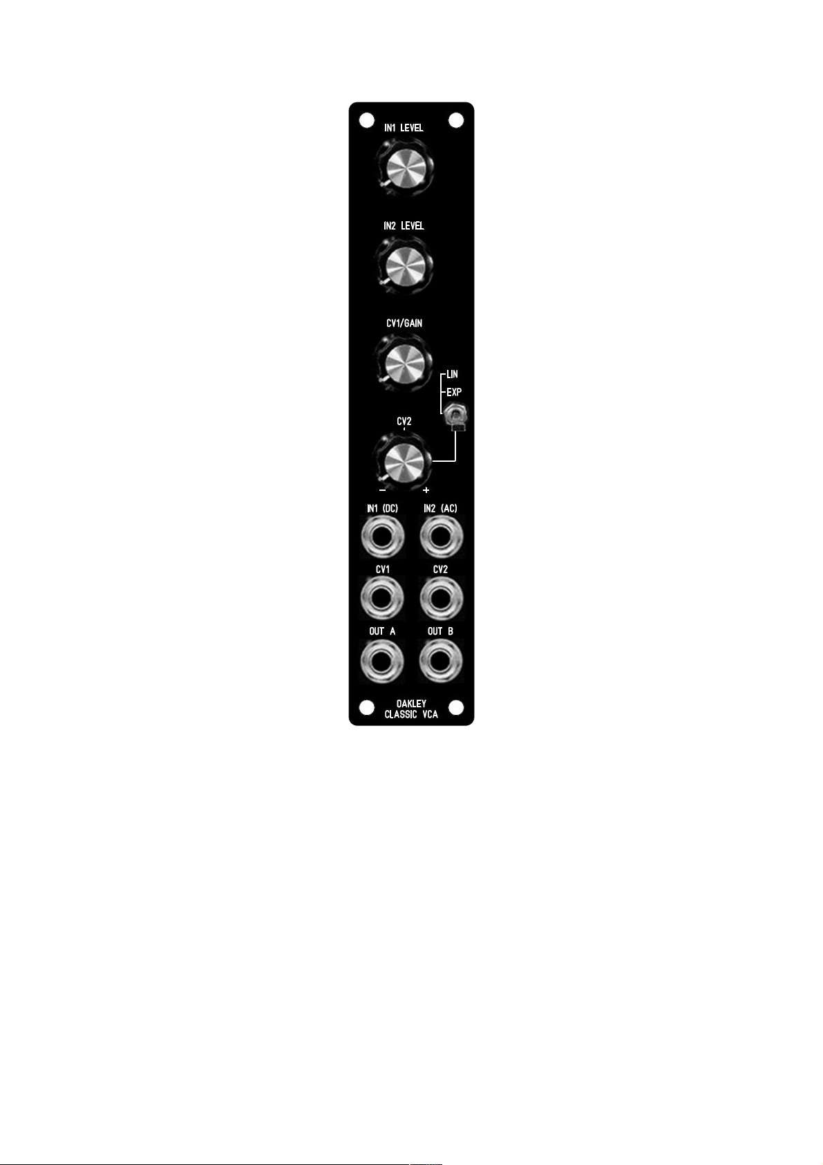
T e signal inputs
The Oakley Classic VCA eatures two input signals, IN1 (DC) and IN2 (AC), and each has its
own level control. In this way, the Classic VCA can be used to mix or sum two signals
together be ore they are processed by the VCA core. One o the inputs, IN1 (DC), is directly
coupled to the VCA core. All signals, CV and audio, connected to this input can there ore be
controlled by the VCA. The other input, IN2 (AC), goes via a capacitor and so is o ten called
'AC coupled'. The capacitor acts to block very low requency signals and steady state
voltages. You can think o it as being a high pass ilter with a very low cut-o requency.
T e CV1 input and gain control
The CV1/GAIN pot controls the 'initial gain' o the module when no jack is inserted into CV1.
This is used to open and close the VCA manually, even when there are no other signals
applied to either o the CV inputs. I any positive CV is applied to CV2 then this will open the
VCA urther. While the addition o a negative CV will actually cause the VCA to close.
With CV1/GAIN pot turned to its maximum value and no jacks inserted in either CV1 or CV2
then the gain produced by the VCA is 0dB or one.
The OUT B output works in reverse o the OUT A socket. When the GAIN pot is set to its
maximum the output level rom OUT B should be at its minimum. However, you should note
that the signal is not completely silent. Unlike OUT A which can be shut o completely when
the VCA is closed, OUT B produces about -50dB o signal cut at its quietest. This is generally
good enough or its intended purposes o ring modulation and auto-panning.
5

Ring modulation is achieved by inserting a 'modulation' signal into CV2 with both the CV2
and CV1/GAIN pots set to their maximum and in LIN mode. Auto-panning, whereby an input
signal is moved back and orth between the le t and right o a stereo signal, can be done by
utilising both OUT A and OUT B. Set the CV1/GAIN pot to the middle position which allows
the input signal(s) to be heard rom both OUT A and OUT B. Then by applying a control
voltage to CV2 you should ind that the audio signal moves between OUT A and OUT B.
As soon as a jack is inserted into CV1 then the CV1/GAIN pot now changes rom a manual
gain pot to a modulation depth control or the CV1 input socket. The pot now controls the
sensitivity o the CV1 input. The CV 1 input is a linear control input.
5V at CV1, with the CV1/GAIN pot set to maximum, will make the gain o the VCA
approximately 0dB or unity. Any CV higher than this will increase the gain proportionately.
However, it should be noted that the output signal level o the VCA cannot exceed +/-12.5V
or so. This upper output limit is restricted by the power supply rails o the modular system.
CV1, or the actions o the GAIN pot, and CV2 will act together too, so it is entirely possible
to get gains o higher than unity i both are set high enough.
T e CV2 input
For CV2 two modes are provided, LIN and EXP:
The LIN input has a linear response. This means that doubling the CV will double the output
amplitude. In general this is the most use ul response or general VCA duties. With the
CV/GAIN pot at its minimum, and the CV2 pot at its maximum, +5V at the CV2 input will
produce a gain o around one, ie. 0dB or unity gain.
The EXP input has an exponential response. This means that a rising CV will produce a
proportional change in gain measured in decibels. In practice this means that the output signal
appears not to quickly increase in level until the input CV is close to 5V. This e ect tends to
produce wonder ully plucky sounds when used with a conventional ADSR as the CV source.
6

Power supply requirements
The design requires plus and minus 15V supplies. The power supply should be adequately
regulated. The current consumption with no output signal is about +/-35mA. Power is routed
onto the PCB by a our way 0.156” MTA156 type connector or the special ive way
Synthesizers.com MTA100 header.
Power connections – MOTM and Oakley
The PSU power socket is 0.156” Molex/MTA 4-way header. Friction lock types are
recommended. This system is compatible with MOTM systems.
Power Pin number
+15V 1
Module ground (0V) 2
Socket ground 3
-15V 4
Pin 1 on the I/O header has been provided to allow the ground tags o the jack sockets to be
connected to the powers supply ground without using the module’s 0V supply. Earth loops
cannot occur through patch leads this way, although screening is maintained.
It's worth illing the empty holes o the PWR pads with solder.
Power connections – Synt esizers.com
The PWR power socket is to be itted i you are using the module with a Synthesizers.com
system. In this case you should not it the PSU header. The PWR header is a six way 0.1”
MTA, but with the pin that is in location 2 removed. In this way location 3 is actually pin 2 on
my schematic, location 4 is actually pin 3 and so on.
Power Location number Schematic Pin number
+15V 1 1
Missing Pin 2
+5V (Not used) 3 2
Module ground (0V) 4 3
-15V 5 4
Socket Ground * 6 5
I itting the PWR header and using it with a standard MU power distribution system, you will
also need to connect together the middle two pads o the PSU header on the main board. This
link connects the socket and panel ground with the module ground. Simply solder a solid wire
hoop made rom a resistor lead clipping, or bit o solid core wire, to join to the two middle
pads o PSU.
7

* The issue 1.1 Discrete VCA boards connect the normally unused pin 6 o the MU connector
to socket ground. With the link on PSU not itted, and using an Oakley MU Dizzy distribution
board with a ive way power cable, will allow the socket ground to be kept separate rom
module ground to prevent ground loops.
Trimmers
Although you can use a simple ine bladed screwdriver or this adjusting the trimmers you
should really use a proper trimmer tool. Vishay, Bourns and others make trimmer adjusters or
less than a pound.
You should make sure your modular has been powered up or at least ten minutes prior to
calibration. Also, it is a good idea to have the room temperature close to what it would
normally be when playing your modular.
OFFSET: Turn the GAIN pot to its maximum level. Ensure all other pots are at their
minimum settings. Measure the output voltage rom the output socket with a good digital
voltmeter. Adjust OFFSET with a jeweller's screwdriver or equivalent until the output voltage
is 0.000V +/- 5mV.
LIN: Insert a 5V peak triangle wave signal at roughly 440Hz to the IN1 (DC) input. Turn the
CV1/GAIN pot to the maximum and the IN1 (DC) and CV 2 pots to their middle positions.
Listen to the output o OUT B on your monitoring system. You should hear a slight
bleedthrough o the triangle wave input. Now adjust LIN until the signal level decreases to its
minimum. You may have to turn up the gain o your monitoring system to ine tune the null
point.
EXP: Insert a 5V peak triangle wave signal at roughly 440Hz to the IN1 (DC) input. Turn the
IN1 (DC) and CV2 pots to their maximum. All other pots should be at their minimum settings.
Connect a 5V source to the CV2 input. This could be a ixed voltage source, a triggered
envelope generator or midi-CV convertor – anything that will give you a +5V output signal.
Now with a scope measure the output voltage at OUT A and adjust EXP until the signal level
in EXP mode is the same as in LIN mode. It doesn't have to be that accurate – within 250mV
will be ine.
I you do not have a scope just simply listen to the OUT A signal and lip the switch rom LIN
to EXP and adjust the EXP trimmer until there is no change in volume when you lip the
switch. It doesn't have to be that accurate, just try to get the two signals sounding roughly the
same.
I you can't get the levels equal then double check the voltage going into CV2. The EXP mode
is very sensitive to changes in level around 5V. I you can't get OUT A loud enough then the
voltage going into CV2 may well be lower than 5V. I it's too loud then the CV may well be
signi icantly over 5V.
8

Final Comments
I hope you enjoy using the Oakley Classic VCA
I you have any problems with the module, an excellent source o support is the Oakley Sound
Forum at Mu wiggler.com. I am on this group, as well as many other users and builders o
Oakley modules.
I you have a comment about this user manual, or have a ound a mistake in it, then please do
let me know.
Last but not least, can I say a big thank you to all o you who helped and inspired me. Thanks
especially to all those nice people on the Synth-diy and Analogue Heaven mailing lists and to
those at Mu wiggler.com orum.
Tony Allgood at Oakley Sound
Cumbria, UK
© August 2012 – updated October 2019
No part of this document may be copied by hatever means ithout my permission.
9
Table of contents
Popular Amplifier manuals by other brands

Cobalt Digital Inc
Cobalt Digital Inc 9915DA Series product manual

Marshall Amplification
Marshall Amplification DSL100HR user manual

Inter-m
Inter-m DPA-5075M i Operation manual

JBL
JBL VMA160 Operation manual

dbx
dbx 286A Owner's operation manual

J&M
J&M ROKKER XXRP 630W Installation and operation instructions