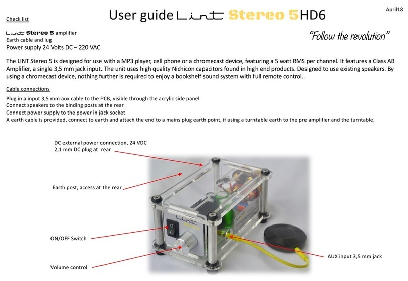
Lint Audio Legend 2 User manual

Lint Legend 2 stereo headphone amplifier
@lintaudio December 20
Type TE1/2 Kit assembly instructions
www.lintaudio.co.za
Download from the website
12AU7 / ECC82 Hybrid Valve audio preamplifier and headphone amplifier

Contents
Introduction
Welcome to the world of kit building
Part 1 -User guide
Part 2 -Introduction
Part 3 –Kit assembly
The schematic and BOM is a
separate file

Welcome to the exciting world of Hifi kit building
Thank you for purchasing a Lint Legend 2 kit. The kit is designed to introduce you to the interesting world of basic electronics.
You will encounter vacuum tubes or valves, mosfets, voltage regulators, resistors, capacitors, transistors as well as soldering.
Some basic tools required
Obviously, some basic tools will be required, no need to go mad acquiring high end test equipment.
A decent multimeter with AC (RMS) DC voltage, current is useful and of course resistance measurement is essential.
Soldering stations are ideal but a decent 220 volt soldering iron will be adequate. If planning on building more kits, then
shell out for a nice station.
Basic hand tools, pliers, side cutters, allen keys are essential whereas and a small vice or third hand is useful.
Before you start
Take a good look at the kit materials. Don’t open the packets until ready to build. Read these instructions thoroughly
and then reflect on the assembly.
When you start the build, secure a nice clean uncluttered workspace, if using the dining room table, ensure that the work
doesn’t get disturbed. Its very annoying to have your layouts disturbed.
We are human, so please check the components values with a multimeter before assembly.
The kit is not supplied with soft solder wire, a valve or a power supply.

User guide Lint Legend 2 TE1
Check list
Lint Legend 2 headphone / pre amplifier with sub output
Earth cable and lug
Power supply 24 Volts DC –220 VAC / 2 pin European plug
ON/OFF Switch
Headphone connection
(disable pre amp output)
Volume control
August 20
“Follow the revolution”
The Lint Legend provides a outstanding analogue sound experience with headphones and a music source, featuring a
Class AB amplifier with a 12 au7 vacuum tube, MOSFET second stage with quality capacitors allowing for an
outstanding sound experience. It is designed for usage as a pre-amp for usage with either a solid state amplifier,
power amplifier or a Lint TE12 monoblock. This is Internally selectable.

Inserting Vacuum tube (Valve)
The Lint Legend is supplied with either a NOS (new old stock) or new 12au7 vacuum tube (valve). All units have been fully tested
at our works with a few hours of burn in.. The design is PURE ANALOGUE and will not perform to expectations without adequate run-in
time.
After approximately 40 hrs expect that smooth rounded experience that only valve technology will be able to provide.
The tubes can only go in one way, and this you notice
by aligning the missing pin with the gap in the base
(receiver).
Push the tubes down with some force, ever so
slightly rocking the tube back and forth, or in
aslightly circular motion. This is where the name
“tube rolling” came from.
You may think you are using too much force for a little
glass tube, but the tubes will slide into their sockets
before they break under your force.

RCA Phono inputs or 3,5 mm jack
(use only one input source)
DC external power connection, 24 VDC
Input, 2,1 mm DC plug
RCA Phono outputs
(for use as a pre amplifier)
Earth post
Plug in a input 3,5 mm aux cable to the PCB, visible through the acrylic rear panel or to the RCA sockets.
Plug in the RCA outputs to a amplifier and the sub to the third RCA socket this is a balanced mono so connect to LFE on sub.
The sub level will adjust with the Legends volume control.
Use power supply supplied with unit at 24vdc
A earth cable is provided, connect to earth and attach the end to a mains plug earth point via a 3 pin plug
Cable connections
Connect headphones to the 3,5 mm audio out socket on the front, this disables pre amp output.
Sub output

Gain selection
Due to the fact that it is very difficult to make a fully universal analogue product. The Legend is so designed that the output gain may be
By the user when used as a pre amplifier. It’s a very simple procedure.
The Legend is factory set at a optimum gain at the output RCA jacks. These have a resistor attenuation bridge behind the sockets.
The standard setting at 150 mv input /1000 hz is 1 volt. This is suitable for usage with most solid state mono-blocks or used as pre amp
replacing the NAD 3020 pre amp. Position 2 is to suit the Lint TE12 monoblock which is 2,1 volts
By special order the Legend maybe configured for other amplifiers such as a Leak Stereo 20 at 150 mv.
Factory set at 1 volt RMS at 1000hz
The headphone 3,5 mm socket
remains at maximum gain
Remove shunt tabs and change over to suit

Tube rolling
The Lint Legend is designed to provide the ultimate music headphone enjoyment. However as most music lovers that have
discovered the benefits of a analogue vacuum tube type of audio amplifier is that the “Legend” is designed to be “tube
rolled” (the name comes from the action of rolling the tube in its socket to insert or remove it).
The Lint Legend uses a 12au7 (ECC82 in Europe). These vacuum tubes are still made to this day. They were first designed in
1946.
By being a dual triode design, it makes it easy to produce a true stereo sound from a single unit. To enable a thermionic
emission, a heater voltage is required. Hence the circuit used deploys a LM317 linear voltage regulator, this sets the heater
voltage to 12,6 volts as both heaters are wired in series. This is factory set just needs checking from time to time.
Each vacuum tube has different characteristics for sound, The fun part is to change the flavour of the sound by trying
different 12au7s or equivalent tubes. It is advisable to search for NOS (new old stock) tubes on the web as this provides an
interesting experience. The Lint Legend has test points allowing easy adjustment of “Bias”. When a new vacuum valve is
inserted, it is advisable to adjust the bias voltage. Set to 12,5 volts after initial warm up and then readjust after 20 mins
being on. This requires checking every 50 hrs.
RV5 Heater trim pot
RV1 Bias Trim pot
TP 4 Connect negative probe
to ground for all tests
TP1 Heater test point
TP3 Bias test point
RV2 Bias Trim pot
TP2 Bias test point

Introduction
The Legend 2 uses the 12 AU7 Vacuum tube with IRL510 MOSFETS.
The 12AU7 and its variants are a miniature nine-pin (B9A base) medium-gain dual triode vacuum tube. It belongs to a large
family of dual triode vacuum tubes which share the same pinout (RETMA 9A). 12AU7 is also known in Europe under its
Mullard Philips designation ECC82. There are many equivalent tubes with different names, some identical, some designed
for ruggedness, long life, or other characteristics.
The kit is designed to introduce an audio enthusiast to vacuum tube technology as well as to improve the audio quality of
available to the listener while providing a stepping stone to more advanced build projects that Lint Audio are developing.
The intention is to create a very exciting and interesting hobby that will never be finished with so many parameters to
experiment with.
Namely
Hybrid vacuum circuit design and tube rolling
MOSFET and voltage regulator technologies
Soldering and circuit assembly techniques
Heat-sink design
The design permits experimenting with many types and supplies of vacuum tubes allowing the user to “roll” or change the
tubes and its adjustable bias. These valves are still made today with many NOS (new old stock available on the web). This is
a highly entertaining exercise.
The kit is not supplied with a valve or a power supply. Most kit builders opt for their own choice.
Lint audio will be able to supply a selection pack of suitable units to allow such experimenting.
PART 2

Types of valve that may be used.
The system is designed around the 12 au7 or also known as ECC82, this is a 3 wire heater circuit, it may use either 13,6 volts
in series or 6,3 volts in parallel .
The PCB is so designed to allow either a Lm317k regulator which may be adjusted to precisely the required voltage.
The B9a base may be wired to suit this on pins 4 and 5.
12au7, E80cc, 5963, CV 4063/6158 and the 12H7 with only Bias adjustment set at about 12,5 volts. No modifications required.
Alternatively, a fixed voltage SMPS (switch mode power supply) maybe used for 6,3 volts for their heaters.
Valves that may be used include a 6sn7 and its military version 5692, its later version the 6cg7.
This also allows a considerable amount of experimenting with many tube variants.
The 6cg7 was introduced as a replacement of the 6sn7. Early versions are quite popular with audio experimenters. The 6sn7
is a general purpose valve and has some very collectable variants.
The PCB is so designed to be able to use a octal 8 pin base due to its larger footprint.
Mullard ECC82 GE 5963 Valvo E80cc Raytheon 6sn7

LM317K variable voltage regulator
The LM317k mounted on the rear panel is used as an adjustable voltage regulator. It is supplied in a T03 package
with a suitable heatsink.
By adjustment of the trim pot RV5 on the PCB it allows the vacuum tube heater voltage to be set at 12,6 volts very
precisely. By using a linear regulator It ensures a smooth noise free power supply to the vacuum tube heaters.
A LM317t is also used as a constant current device to supply the power MOSFET output transistor.
These devices require the large heatsinks as excess power is wasted in the form of heat.
The use of a linear regulator it ensures that a noise free power supply which, in turn, allows for the possibility of a
smooth analogue sound experience.

MOSFET output transistor
The IRF 510 is used as second stage amplifier from the vacuum
tube. It gives the advantage of modern electronic components
coupled to the pure analogue experience of vacuum tubes.
The best of both worlds !
The main advantage of a MOSFET is that it requires almost no
input current to control the load current, when compared with
bipolar transistors. In an enhancement mode MOSFET, voltage
applied to the gate terminal increases the conductivity of the
device.
MOSFET showing gate (G), body (B),
source (S) and drain (D) terminals. The
gate is separated from the body by an
insulating layer (pink).

Resistor component codes
If in doubt, always check values with a multimeter

Capacitor codes
Power and output capacitors are polarised electrolytic, the device is marked and the
long leg is always the positive

Soldering with examples of a dry solder joint
Always ensure that the joint is not moved whilst
cooling, this will cause a matt finish. A shiny joint
will be correct joint.
Please ensure that you use a fine tipped soldering iron
DO NOT OVERHEAT JOINTS WHEN SOLDERING

Diode mounting Bending a component lead
Take care when bending a component lead not
to damage the “die” of the component.
Always use pliers to prevent undue strain on the
die.
Always ensure a diode is correctly
Inserted to the PCB or the system
will not work.

Kit assembly
Introduction
It is expected that the kit builder has some soldering experience. The kit is level 2.
Always use a fine tipped soldering iron. It is not advisable to use a heavy industrial unit. Use fine solder when assembling.
It is expected that the builder has a knowledge of basic electronic components, layouts and tools.
A smartphone will aid in determining left and right headphone connections when connecting. Download a “left and right”
app from an app store as this makes it very simple to set the correct output when assembled.
Benzine and a small toothbrush will be required to clean the solder flux residue from the printed circuit board when complete.
The kit is supplied as a complete package, the assembled kit works and has been in service. It performs to expectations.
The power supply and valve are not supplied. Soft solder is not supplied.
When assembling, ensure that components are not overheated by poor assembly equipment.
Completed units are available on request.
When using soft solder, always wash hands before consuming foodstuffs, avoid contact with lead
and other corrosive materials
Part 3

10
10
9
9
8
8
7
7
6
6
5
5
4
4
3
3
2
2
1
1
HH
GG
FF
EE
DD
CC
BB
AA
Size Document Number
Rev
Date: Sheet of
Drawn by Norman Ellis P.C.B. Design Services - Ph: 083 2656558
7
Airmagic
A4
11Thursday, September 10, 2020
.
LINTAUDIO LEGEND HEADPHONE AMPLIFIER
Size Document Number
Rev
Date: Sheet of
Drawn by Norman Ellis P.C.B. Design Services - Ph: 083 2656558
7
Airmagic
A4
11Thursday, September 10, 2020
.
LINTAUDIO LEGEND HEADPHONE AMPLIFIER
Size Document Number
Rev
Date: Sheet of
Drawn by Norman Ellis P.C.B. Design Services - Ph: 083 2656558
7
Airmagic
A4
11Thursday, September 10, 2020
.
LINTAUDIO LEGEND HEADPHONE AMPLIFIER
C11
47uF
25V
C11
47uF
25V
C13
100nF
63V
C13
100nF
63V
J8
RCA
AUDIO OUT R
J8
RCA
AUDIO OUT R
1
2
R8
1k
R8
1k
R19
1k
R19
1k
C7
100nF
63V
C7
100nF
63V
RV1
5k
RV1
5k
13
2
C9
1uF
400V
C9
1uF
400V
P1
DS-210-A
24V IN
P1
DS-210-A
24V IN
1
2
3
D2
RED
Front
D2
RED
Front
J4
RCA
AUDIO IN L
J4
RCA
AUDIO IN L
1
2
H1
3SIP100
H1
3SIP100
1
2
3
R5
3k3
R5
3k3
Q2
2N3906
Q2
2N3906
3
2
1
R16
200R
R16
200R
D1
RED
Bottom
D1
RED
Bottom
C2
2200uF
35V
C2
2200uF
35V
RV2
5k
RV2
5k
13
2
S1
DPDT2WRA
ON/OFF
S1
DPDT2WRA
ON/OFF
RV4
10k log
VOLUME
RV4
10k log
VOLUME
1
2
3
12AU7
V1-1
12AU7
V1-1 1
2
3 4
R9
1k
R9
1k
D4
BL-B4441
Amber
D4
BL-B4441
Amber
R12
270R
R12
270R
J5
RCA
AUDIO IN R
J5
RCA
AUDIO IN R
1
2
C14
100nF
63V
C14
100nF
63V
U1
LM317
U1
LM317
Vin
3
Adj 1
Vout
2
R17
1k5
R17
1k5
Q4
IRL510
Q4
IRL510
2
1
3
C12
470uF
25V
C12
470uF
25V
J7
RCA
AUDIO OUT L
J7
RCA
AUDIO OUT L
1
2
R1
8R2
R1
8R2
R21
SOT
R21
SOT
C6
1uF
100V
C6
1uF
100V
D3
1N4007
D3
1N4007
U2
LM317
U2
LM317
Vin
3
Adj 1
Vout
2
R10
22k
R10
22k
C4
100nF
63V
C4
100nF
63V
U5
LM350K
U5
LM350K
Vout
3Vin 2
Adj
1
C5
1uF
100V
C5
1uF
100V
R15
1k5
R15
1k5
RV3
10k log
VOLUME
RV3
10k log
VOLUME
1
2
3
C8
1uF
63V
C8
1uF
63V
R6
47R
R6
47R
R13
1k
R13
1k
Q1
2N3906
Q1
2N3906
3
2
1
Q3
IRL510
Q3
IRL510
2
1
3
R4
220R
R4
220R
R14
1k8
R14
1k8
R11
22k
R11
22k
TP5
GROUND
TP5
GROUND
D5
1N4007
D5
1N4007
12AU7
V1-2
12AU7
V1-2 6
7
8 5
TP3
BIAS
TP3
BIAS
H2
3SIP100
H2
3SIP100
1
2
3
TP4
GROUND
TP4
GROUND
TP2
BIAS
TP2
BIAS
R20
1k
R20
1k
R3
220R
R3
220R
J9
K3610D
HEADSET
J9
K3610D
HEADSET
1
3
2
4
5
TP1
Heater
TP1
Heater
R2
8R2
R2
8R2
J1
K3610A
AUDIO IN
J1
K3610A
AUDIO IN
1
3
2
J10
RCA
SUB W OOFER
J10
RCA
SUB W OOFER
1
2
R7
47R
R7
47R
C1
2200uF
50V
C1
2200uF
50V
R22
200R
R22
200R
C10
1uF
400V
C10
1uF
400V
C3
4700uF
35V
C3
4700uF
35V
RV5
1k
RV5
1k
1 3
2

Overlay of components

Complete kit of parts with each bag labeled with a part number
Table of contents
Other Lint Audio Amplifier manuals

