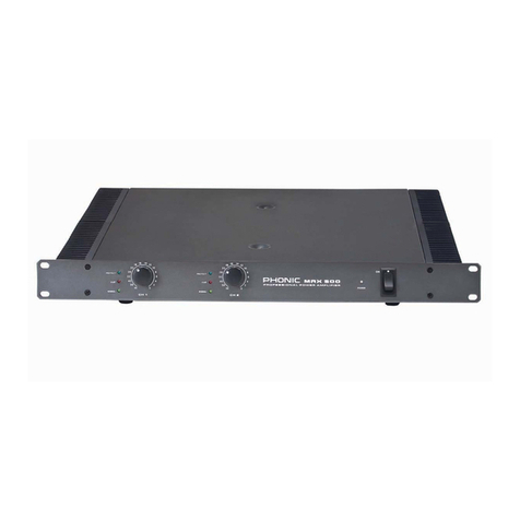
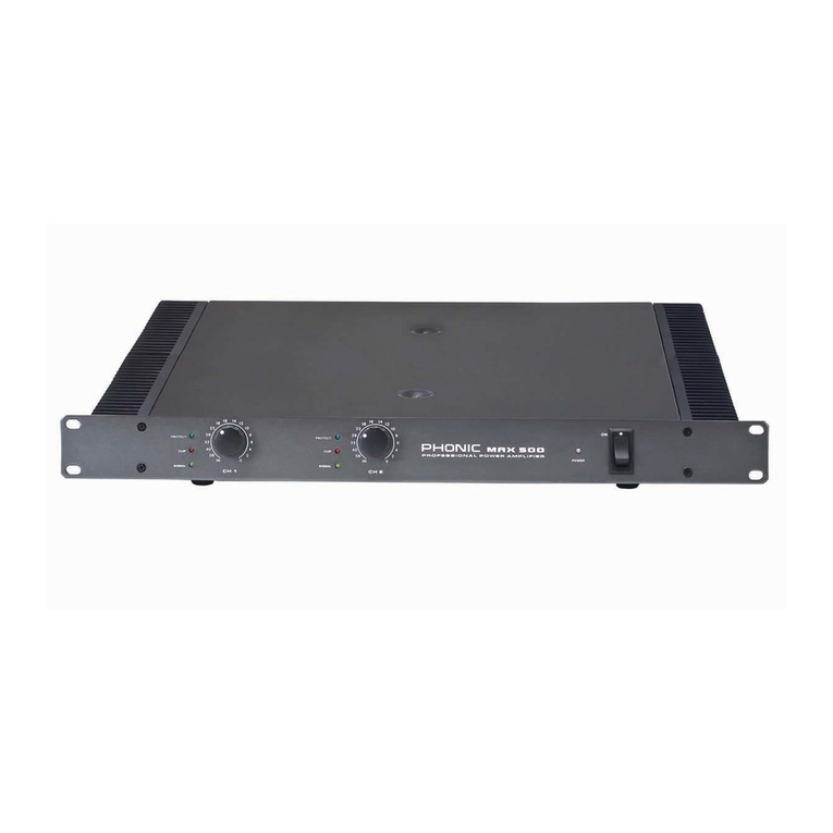
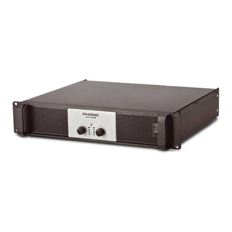
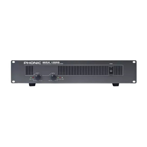
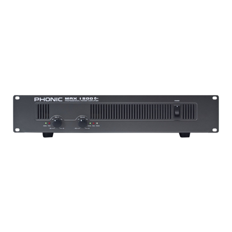
Phonic MAX Series User manual


PHONIC CORPORATIONMAX SERIES USER’S MANUALPage 2
SAFETY PRECAUTIONS
!!! WARNING !!!
TO REDUCE THE RISK OF FIRE OR ELECTRIC SHOCK,
DO NOT EXPOSE THIS UNIT TO RAIN OR MOISTURE.
Avoid exposing rain, water, or any form of liquid to this unit. IMMEDIATELY unplug its power cord from its
power source and contact a qualified technician when the unit is exposed to rain, water, or any form of
liquid.
Keep the unit is away from heat sources like radiators, heat registers, stoves and etc.
ALWAYS have a qualified technician present when repairing or modifying this unit.
The arrowhead lightning flash symbol within an equilateral triangle is intended to alert you to the
presence of uninsulated “dangerous voltage”inside the enclosure that may be sufficient to
constitute a risk of shock.
The exclamation point within an equilateral triangle is intended to remind you to the presence of
important operating and maintenance instructions in the literature accompanying the product.
!!! CAUTION !!!
TO REDUCE THE RISK OF ELECTRIC SHOCK,
DO NOT REMOVE THE COVER OR THE BACK OF THE UNIT.
No user-serviceable parts inside. Always contact a qualified technician for repair or modification.
DO NOT open, modify, or disassemble the unit without a qualified technician present. Any change or
repair of the unit requires the present of a qualified technician in order for the warranty to remain effective.
Clean the unit with damp cloth and dry brush. No other solvents are recommended for cleaning. Routine
cleaning and proper maintenance guarantee best performance from the unit.
Carefully packed at the manufacturing site, the packing box is designed to protect the unit from rough
handling. Please carefully examine the content inside the package and make sure the unit is well,
undamaged.
Notify your dealer and the shipping company immediately when you find the unit damaged from shipping.
Claims for damage or replacement would only be granted when reported properly and in a timely manner.
Use damp cloth or dry brush to clean the unit. DO NOT use any other solvents for cleaning. Good care
and maintenance of your unit will prolong your unit’s operational life and insure its optimal performance.

CONTENTS
PHONIC CORPORATION Page 3MAX SERIES USER’S MANUAL
INTRODUCTION....................................................4
FEATURES.............................................................4
GETTING STARTED.............................................4
INSTALLATION..................................................5
1 HEAT VENTILATION...................................5
CONNECTIONS.........................................................6
2 INPUT........................................................6
3 OUTPUT.....................................................6
OPERATION........................................................7
FRONT PANEL DESCRIPTION
4 POWER SWITCH............................................7
5 POWER LED...............................................7
6 PEAK LED................................................7
7 SIGNAL LED.............................................7
8 GAIN CONTROLS.......................................7
REAL PANEL DESCRIPTION
9 PARALLEL/STEREO/
BRIDGE MONO OPERATION MODE..................7
10 HIGH PASS FILTER..................................11
11 LIMITER ON/OFF..................................11
12 GROUNDING - FLOATING SWITCH..........11
13 CHASSIS GROUNDING
CONNECTING POINT.........................................11
14 POWER CORD.......................................11
PROTECTIONS.................................................12
DIMENSIONS ...............................................13
SPECIFICATIONS.....................................14
SYSTEM BLOCK DIAGRAM.....................15

INTRODUCTION
Thank you for purchasing a Max series power am-
plifier. Based on years of experience in designing
and manufacturing professional audio equipment,
we at PHONIC designed this power amplifier for
those who need an extremely powerful, reliable and
sturdy amplifier with a small footprint. Taking ad-
vantage of its huge heat sink as well as its variable
speed fan that auto-adjusts fan speed depending
on the temperature of the machine during opera-
tion, Max series power amplifier can only promise
to perform at its best. Its professional quality out-
put and its sturdy case design make this unit great
for various locations like churches, concert tours,
stages, disco, pubs, or any place that requires
amplifier installation.
This unit is designed with great care and great at-
tention to details, so please read this manual care-
fully. Look after it and keep it in a safe place for
future reference.
FEATURES
zUp to 1500 watt with only 2U footprint
zOutput: 300W for Max 860, 450W for Max 1500
and 750W for Max 2500
zHigh current toroidal transformer allowing high
power output with low noise and low distortion
zBuilt in limiter with a button allowing user to dis-
able limiter’s function
zSelectable high pass filter at 30Hz or 50Hz for
reducing distortion and protecting speakers
zBalanced XLR-TRS combo input jack
zBinding post and speakon outputs
zFront mounted gain controls for easy access
zSignal and Peak LED indicators to monitor per-
formance
zProtection: short circuit, thermal, subsonic, RF
protection, output DC offset, power on/off muting
PHONIC CORPORATIONPage 4
INTRODUCTION / FEATURES / GETTING STARTED
MAX SERIES USER’S MANUAL
GETTING STARTED
zCheck the AC voltage before connecting the power
plug to the outlet. Make sure the AC power sup-
ply shares the same voltage used in your coun-
try (For example, while some countries use 100V,
others use 120V, 230V, or 240V). Proper
grounding prevents user from experiencing elec-
trical shock.
zBefore turning on the power, make sure gains
are turned down to prevent other equipment from
harm.
zCheck your cables regularly and label each end
clearly for easy identification.
zAlways turn off the power before connecting to
and disconnecting from the unit.
zNEVER use solvents to clean the unit. Clean it
with a soft and damp or dry cloth.
PHONIC CORPORATION Page 5MAX SERIES USER’S MANUAL
INSTALLATION
INSTALLATION
MOUNTING THE UNIT
Designed to fit into a standard 19-inch equipment
rack, this unit only takes up 2-rack space. Secure
this unit with 4 rack-mount screws and cup wash-
ers. In general, power amplifiers usually are heavier
than any other audio equipment, so when installing
this unit onto a rack, begin placing it from the bot-
tom of the rack. Leave 1-rack space between power
amplifiers to guarantee better cooling (See Figure
1).
1 HEAT VENTILATION
This unit comes with variable speed fan that auto-
adjusts fan speed depending on the temperature of
the machine during operation. Front to back air-
flow is how heat leaves the unit. !!! SO DO NOT
PLACE ANY OBJECT THAT MAY PREVENT HEAT
FROM EXITING THE UNIT FROM ITS BACK VENT
!!!

PHONIC CORPORATION
MAX SERIES USER’S MANUAL
Page 6
CONNECTIONS
2 INPUT
With balanced XLR and TRS 1/4
”
input jacks, user
could use either XLR or TRS line input jack for con-
nection. These input jacks accept balanced as well
as unbalanced input. When sending unbalanced
signal, the Ring and the Sleeve of the TRS jack
must be connected, the 3rd pin and the 1st pin of
the XLR connector should be connected as well, or
simply just use a TS phone jack for making the
connection (See Figure 2).
3 OUTPUT
Binding posts and speakon connectors make up
the unit’s output section. Loudspeakers can eas-
ily be connected using banana plugs, spade lugs,
CONNECTIONS
bare wires or speakon connector. More people pre-
fer using speakon than other connectors because
it’s the least likely to be disconnected by accident
or electrical shock. Because speakon comes with
four wires inside, you can connect to two speakers
with only one channel output. Becareful when mak-
ing connections since improper connecting could
cause the unit to short circuit. The minimum im-
pedance setting for STEREO and PARALLEL op-
eration is 4ohm while 8ohm is the minimum setting
for BRIDGE MONO (See Figure 3).
aaaaaaaa
aaaaaaaa
aaaaaaaa
aaaaaaaa
aaaaaaa
aaaaaaa
aaaaaaa
aaaaaaa
aaaaa
aaaaa
aaaaa
aaaaa
aaaaa
aaaaa
aaaaa
aaaaa
aaaaa

OPERATION
PHONIC CORPORATION Page 7
MAX SERIES USER’S MANUAL
OPERATION
FRONT PANEL DESCRIPTION
4 POWER SWITCH
This switch turns on the power of the unit. Re-
member to turn down the gain controls before pow-
ering on or off this unit, even though it comes with
POWER ON / OFF MUTING feature. In general,
power amplifier should be the last audio equipment
to be powered on, and the last one to be powered
off in a PA system.
5 POWER LED
The blue LED comes on when power is on.
6 PEAK LED
When the input signal level becomes too high, caus-
ing input signal to loss definition and to distort, this
red LED comes on. When this happens, turn down
the gain control until the PEAK LED doesn’t come
on constanty or remain on continously.
7 SIGNAL LED
Every channel comes with a signal LED, allowing
user to monitor signal level. A minimum level of
-30dBu is required for the LED to go on.
8 GAIN CONTROLS
These two rotary knobs control the signal level of
the input. Center detented control allows precise
volume setting. Slowly turn the knob clockwise to
increase input level, but make sure that PEAK LED
will not remain on or blink constantly.
REAL PANEL DESCRIPTION
9 PARALLEL / STEREO / BRIDGE MONO OP-
ERATION MODE
There are three operation modes for different use.
To avoid damaging your PA system, remember to
first power off the unit before switching from one
mode to the other.
PARALLEL
Switch to PARALLEL mode, the input signal of
Channel 2 parallels the input signal of Channel 1,
so only one input jack is needed for the signal
source. While Channel 1 input is being used for
source, Channel 2 input can be used to extend the
source signal to other audio equipment, for example,
another power amplifier. Even though the input sig-
nal of both channels parallels each other, the out-
put level of each channel is determined by its own
independent gain controls. So the two channels
sharing the same signal do not share the same
output level (See Figure 4).

OPERATION
PHONIC CORPORATIONPage 8 MAX SERIES USER’S MANUAL

OPERATION
PHONIC CORPORATION Page 9MAX SERIES USER’S MANUAL
STEREO
STEREO mode is the most frequently used mode
among the three. Each channel is independent of
the other, carrying its own input signal, with its own
gain control. Stereo mode comes in left and right
channels (See Figure 5).
A) When one channel is assigned for left channel,
make sure the other channel is assigned for
the right.
B) User can use the unit for mono output, with
one as main and the other as monitor.
C) This power amplifier can also be used for bi-
amplification. One channel for driving low fre-
quencies while the other for driving high frequen-
cies.

OPERATION
PHONIC CORPORATIONPage 10 MAX SERIES USER’S MANUAL
BRIDGE MONO
This mode is for those who need high level output.
It combines the power of both channels to produce
the maximum amount of power the unit can handle.
Make sure your speaker can handle higher watt-
age this mode offers. Remember, the minimum im-
pedance requirement is 8-ohm. When bridge mono,
make sure only Channel 1 input is in use. When
using speakon, treat PIN 1+ as the “+” and PIN
2+ as the “-”; when using binding posts, treat Chan-
nel 1 + as the “+” and Channel 2 + as the “-”. Do
not use Channel 2’s speakon output in this mode.
When bridge mono, the gain control of Channel 1
controls the total level output (See Figure 6).
WARNING: Bridge mono operation produces higher
current output than the other two operations, thus
make sure the gain is set at the proper level and
speakers being used can handle the wattage am-
plifier produce. Proper attention to wiring is greatly
needed to prevent experiencing electric shock.

OPERATION
PHONIC CORPORATION Page 11MAX SERIES USER’S MANUAL
10 HIGH PASS FILTER
With this filter, any frequency below 30Hz or 50 Hz
is left out, not reproduced by the amplifier. This
way, speakers less efficient and effective in repro-
ducing low frequencies can be protected. This also
allows such speakers to perform better.
11 LIMITER ON/OFF
This switch turns on or off the built-in limiter. When
the input signal level becomes too high, causing
amplifier to loss definition and to distort. Limiter
helps prevent signal from losing definition and be-
coming distorted by automatically decrease signal
level for guaranting maximum dynamic range.
12 GROUNDING – FLOATING SWITCH
This switch allows user to choose between circuit
or chassis grounding for resolving any grounding
conflict. Under normal use and for safty, such
switch should be in the “grounding on” position.
When grounding loop and hum occur, try switching
to “floating.” When the hum is gone, it means the
common ground is on the other equipment.
13 CHASSIS GROUNDING CONNECTING POINT
To avoid the possibility of ground loop, this unit
comes with chassis grounding point allowing it to
be connected to other units for sharing a common
grounding.
14 POWER CORD
This cord draws electricity from power outlet. Near
by it, there is an indicator that tells you what volt-
age your unit operates in. Check the AC voltage
before connecting the power plug to the outlet.
Make sure the AC requirement shares the same
voltage used in your country (For example, while
some coutries use 100V and 120V, others use 230V
and 240V).

PHONIC CORPORATIONPage 12 MAX SERIES USER’S MANUAL
PORTECTIONS
PROTECTIONS
The unit comes with many circuitry protection fea-
tures for preventing it and speakers it’s connected
to from harm.
SHORT CIRCUIT: When speakers short circuit,
this feature protects the amplifier by cutting off the
output current to the speakers.
THERMAL: Heat is created during high level out-
put – especially when during bridge operation. The
unit comes with variable speed fan that auto-ad-
justs speed depending on the temperature of the
machine during operation. However, for some rea-
son the unit could not effectively vent out exces-
sive heat, this feature would protect the unit from
over-heating by shutting its power off.
OUTPUT DC OFFSET: When direct current enters
to the connection between the power amplifier and
speakers, it hurts the speakers by causing drivers
and cones to work under stress. This feature pre-
vents this from happening by cutting off the output
current to the speakers when such situation hap-
pens.
POWER ON / OFF MUTING: There is a two to
three second delay before the unit sends out any
signal. During this 2-3 seconds, the system will
be on mute, no signal exist this unit.
SUBSONIC: Frequencies below 10Hz contain high
level of energy that can be harmful and stressful for
many speakers. Since normal human listening
range from 20Hz to 20KHz, this unit comes with a
feature that helps filter out any frequency that is
below 10Hz to prevent speakers from harm.
RF PROTECTION: Radio Frequency is everywhere.
This feature prevents radio frequency interference
by filtering out frequency signal that’s above
200KHz. This help prevent radio program signals
from entering this unit.

DIMENSIONS
PHONIC CORPORATION Page 13MAX SERIES USER’S MANUAL
DIMENSIONS
MAX series share the same dimensions.
Measurements are shown in mm/inch.

SPECIFICATIONS
SPECIFICATIONS
All specifications are subject to change without notice.
PHONIC CORPORATIONPage 14 MAX SERIES USER’S MANUAL

PHONIC CORPORATION Page 15MAX SERIES USER’S MANUAL
SYSTEM BLOCK DIAGRAM
SYSY
SYSY
SYSTEM BLSTEM BL
STEM BLSTEM BL
STEM BLOCK DIAOCK DIA
OCK DIAOCK DIA
OCK DIAGRAMGRAM
GRAMGRAM
GRAM

This manual suits for next models
3
Table of contents
Other Phonic Amplifier manuals

Phonic
Phonic T8300 User manual

Phonic
Phonic XP 3000 User manual

Phonic
Phonic ZA200B User manual

Phonic
Phonic KA720 User manual

Phonic
Phonic MK15 User manual

Phonic
Phonic XP 2000 User manual

Phonic
Phonic XP 600 User manual

Phonic
Phonic XP1000 User manual

Phonic
Phonic ICON 300 User manual

Phonic
Phonic DMX1501 User manual

Phonic
Phonic XP6000 User manual

Phonic
Phonic XP 3000 User manual

Phonic
Phonic MAX 250 User manual

Phonic
Phonic MAX 2500 plus User manual

Phonic
Phonic XP 2000B User manual

Phonic
Phonic MAX 1000 User manual

Phonic
Phonic iAMP 1620 User manual

Phonic
Phonic iAMP3020DSP User manual

Phonic
Phonic POWERPOD 820 User manual

Phonic
Phonic ZA100 User manual